Thwaites Mach 443 Assembly instructions

Tier II: Issue 4
T0473
Mach 443, Mach 444, Mach 474,
Mach 475
Operator’s
Instruction
Manual
3 - 4.5 Tonne (Hydrostatic)
Mach 475 - 3 Tonne Hi-SwivelMach 474 - 3.5 Tonne Powerswivel

Introduction
Safety Symbols
• Attention!
• Be alert!
• Your safety is involved!
• Correct action • Incorrect action/procedure
which should NOT be carried
out
CAUTION
WARNING
DANGER
Signal words:
Signal words are used on the machine and within this manual to identify levels of hazard seriousness:
Thwaites Limited puts Safety First
It is the policy of Thwaites Limited to promote safety in the
operation of its machines and to create a general awareness of
site safety and safe working practices for the operators of its
machines.
This Operator’s Instruction Manual is intended for both new
and experienced machine operators. It should remain with
the machine at all times. All operators should be aware of its
location and contents.
It is important that all operators are fully trained and familiar
with the machine and that they have read and understood the
information contained within this book before they attempt
to operate in the site conditions for which the machine was
designed.
This book details practices and operations which Thwaites
Limited recommends. DO NOT operate this machine in ways
other than those detailed within this book.
This machine is designed for customary construction site
operations, and the transportation of bulk materials commonly
carried on such sites; that is their ‘intended use’. Under certain
controlled conditions the dumper may be used for towing
wheeled loads.
Due to the varied nature of the operation of site dumpers and
the absence of an agreed test standard, any gures quoted
by Thwaites in relation to vibration values and exposure are
for reference purposes only. It is the responsibility of the
employer to assess vibration exposure based on the actual site
conditions, and operating practices, at the point of use.
Hand Arm Vibration - The daily exposure Action/Limit Values
of between 2.5 - 5.0m/s2 (A8) are unlikely to be exceeded in an
eight-hour reference period.
Whole Body Vibration - The daily exposure can only be
accurately determined at the point of use. This exposure must
be managed in respect of the Action/Limit Values of 0.5 and
1.15 m/s2 (A8) respectively.
Employers should not rely solely on published vibration
gures when undertaking risk assessments. Depending on the
site conditions, cycle times may need to be adjusted in order
to reduce operator exposure levels.
Vibration values based on typical duty cycles are available
on request from Thwaites. These may be used for reference
purposes only.
1
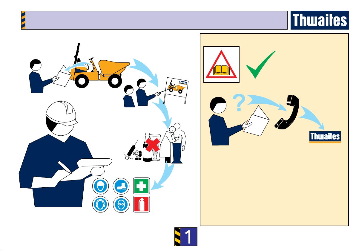
Complete Checks in Section Before Starting The Engine
1 Contact your Thwaites dealer in case of further
questions
2 Learn to operate this machine
3 Ensure you are t to operate
4 Wear correct safety clothing and ensure that safety
equipment is available
Before operating this machine
Distributor
Read this manual
1
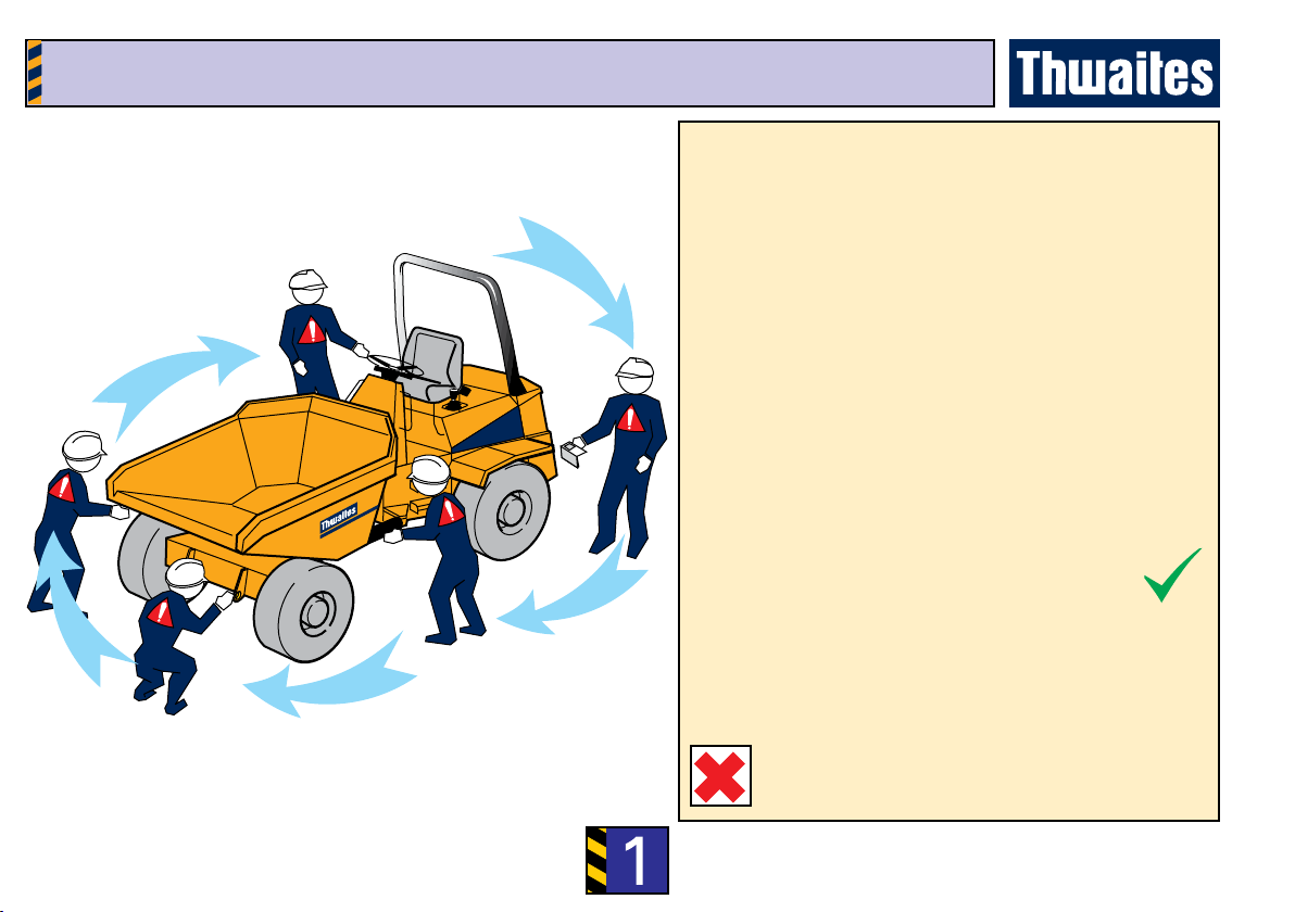
Complete Checks in Section Before Starting The Engine
Walk Around The Machine
Visually check the machine
1 Are the chassis lock and the skip lock disengaged?
2 Are the controls, crush zone and hydraulic rams
clean, and clear of debris?
3 Is the Roll-Over Protective frame (ROPS frame)
secure, fully upright and undamaged?
4 Is the seatbelt anchorage secure and serviceable?
5 Are the covers and mudguards secure?
6 Are the hoses free from uid leaks?
7 Are all safety decals legible?
8 Are the tyres free of cuts or splits?
9 Are all bolts tight and in position?
10 Are the steering wheel and the steering column
undamaged?
11 Have the daily maintenance tasks been
performed? (See rear cover)
Report all faults immediately.
Before operating this machine
DO NOT OPERATE THE MACHINE UNTIL
ALL FAULTS HAVE BEEN RECTIFIED.
1
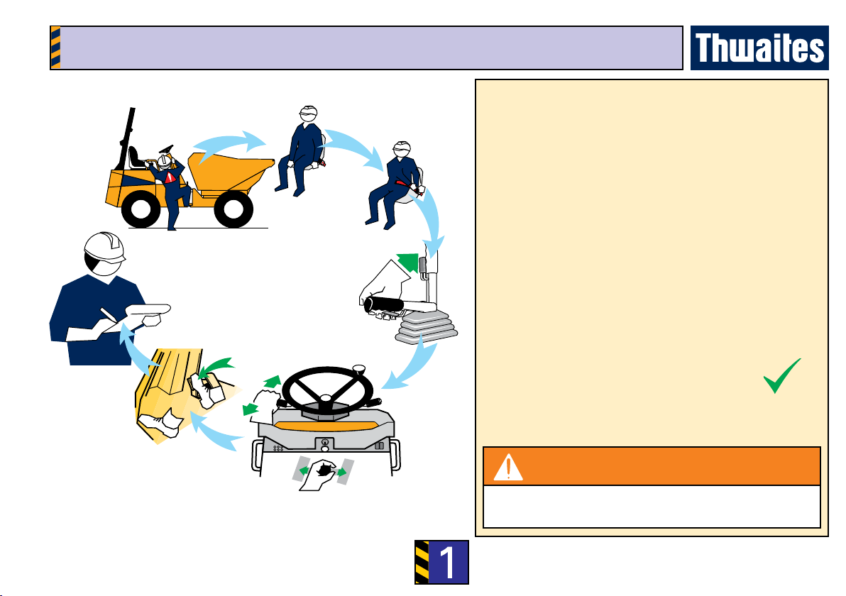
Complete Checks in Section Before Starting The Engine
Mount the machine and check the controls
1 Use the grabrails and foot steps provided to
manoevre into seating position. Face the machine
at all times when mounting and dismounting
2 Is the engine cover secure and locked?
3 Adjust the seat position for comfort and easy
access to controls
4 Fasten the seatbelt. Adjust accordingly for safety
and comfort
5 Is the hand brake ON?
6 Set the transmission to neutral
7 Does the foot brake feel rm?
8 Do not operate the machine without understanding
all its controls as described in the following pages
WARNING
Seatbelt MUST BE WORN when operating machines
tted with a ROPS frame.
Before operating this machine
1
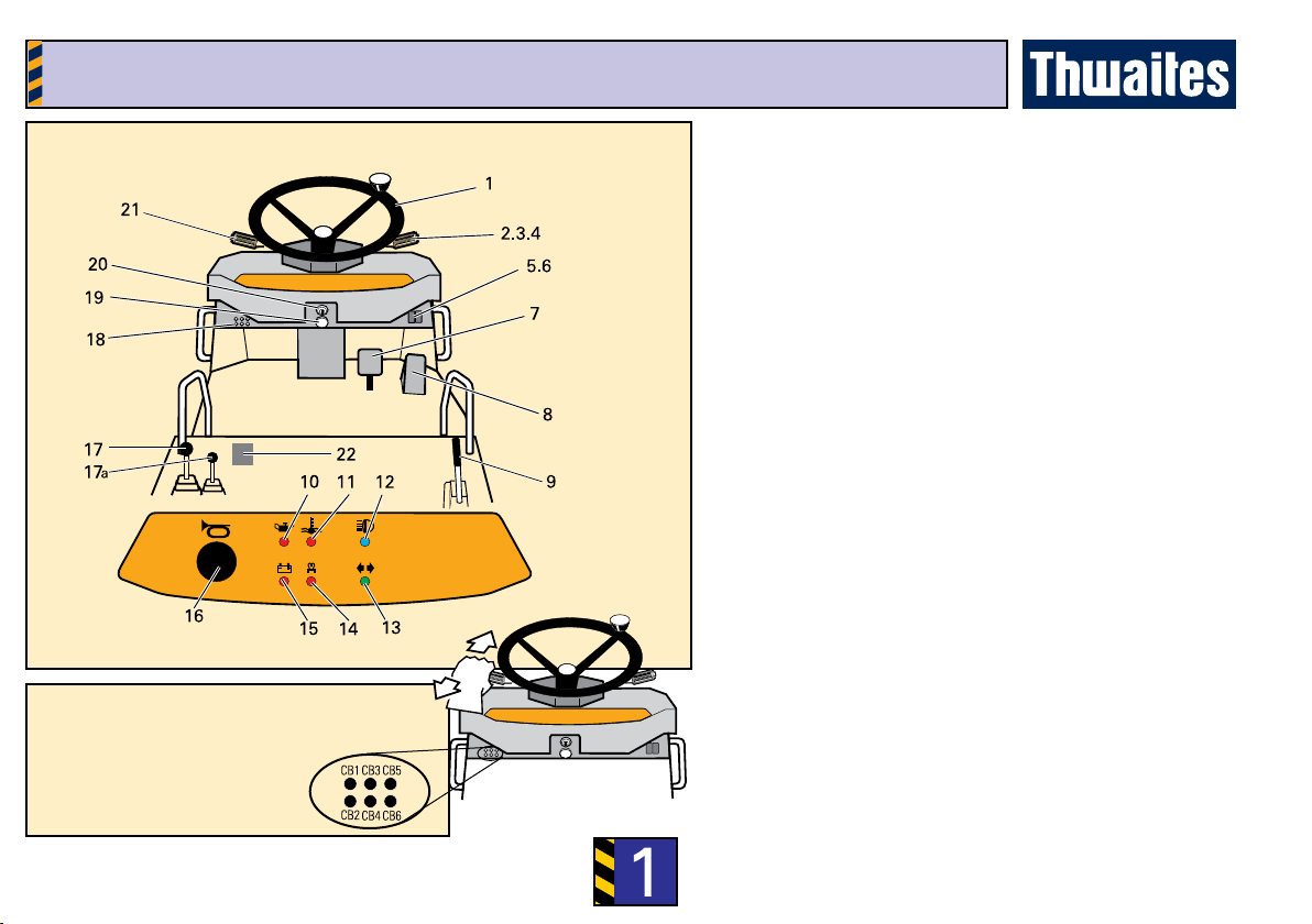
Complete Checks in Section Before Starting The Engine
Control locations & functions
1 Steering wheel.
2 Direction lever -
forward = left turn - back = right turn.
3 Lights - twist 1 = sidelights ON - twist 2 =
Dipped headlights ON
4 Up = ash. Down = main beam
5 Hazard warning light switch
6 Beacon switch*
7 Foot brake pedal/inching
8 Throttle pedal
9 Hand brake lever
10 Engine oil pressure warning light
11 Water temperature warning light
12 Headlamp main beam pilot light
13 Direction indicator pilot light
14 Heat/start pilot light
15 Battery charging warning light
16 Horn push
17 Skip-tip and Skip-rotate lever
17a Skip-raise lever (Hi-Swivel only)
18 Circuit breakers (push to reset)
19 Warning buzzer
20 Ignition switch
21 Forward/Reverse/High/Low Speed Lever (FNR
lever)
22 Maxi fuse (under engine cover)
CB1 Fuel/direction solenoids
CB2 Instrumentation/warning
CB3 Lights
CB4 Flash
CB5 L/H sidelights
CB6 R/H sidelights
Layout of controls
1
Complete Checks in Section Before Starting The Engine
7
8
Control Functions – in depth
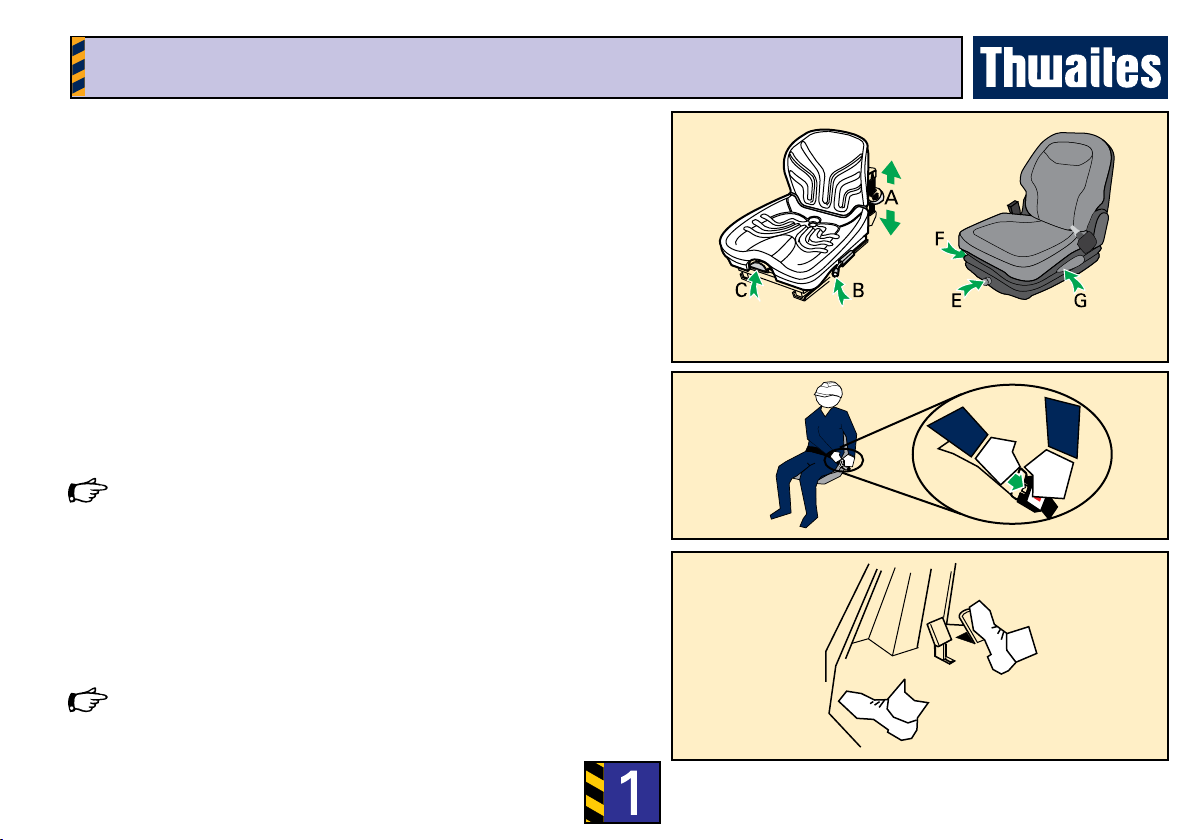
Seatbelt (if tted)
• Adjust length of belt when seated on machine
• Press buckle blade into buckle lock
• Pull belt webbing through buckle blade to remove slack
Seatbelt should not be worn loose. It should pass comfortably across the
hips and not the abdomen.
Throttle pedal – right foot
• Apply pressure to increase speed
• Release pressure from the pedal to reduce speed
Foot brake pedal+inching pedal – right foot
• Push down on the pedal to slow/stop the machine.
Use left foot when inching is required.
Push down while pressing throttle pedal (8) with right foot and release to
move machine.
Seat adjustment
Type 1:
A – Push down to set driver weight (seat empty)
Push fully down and release to reset (seat empty)
B – Lift to slide seat assembly forwards/backwards
C – Lift to slide cushion forward and set backrest
Type 2:
E – Turn knob to set driver weight
F – Lift to slide seat assembly forwards/backwards
G – Lift handle to adjust backrest Type 1 Type 2

1
Complete Checks in Section Before Starting The Engine
Hand brake lever – right hand
When the machine is stationary (or in an emergency):
• Pull up to apply
• Pull catch and lower to release
An audible warning device is fitted to your machine. This will sound when
the hand brake is engaged and the engine is running.
FNR/High and low speed lever – left hand
• Push forwards to travel in a forward direction
• Lever centred = neutral.
• Pull back to travel in a reverse direction
Twist lever anti-clockwise (2) for HIGH speed travel
Twist lever clockwise (1) for LOW speed travel
Opening and closing the engine cover
• Insert ignition key and turn anti-clockwise to unlock
• Pull handle to release and raise cover
• Lower cover, secure and lock before driving
Control Functions – in depth

1
Complete Checks in Section Before Starting The Engine
Steering wheel – both hands
• Turn the wheel clockwise to turn machine to right
• Turn the wheel anti-clockwise to turn machine to left
Ensure the non-steering hand is on the engine cover grabrail when using the
spinner knob for low-speed single-handed steering.
Control Functions – in depth
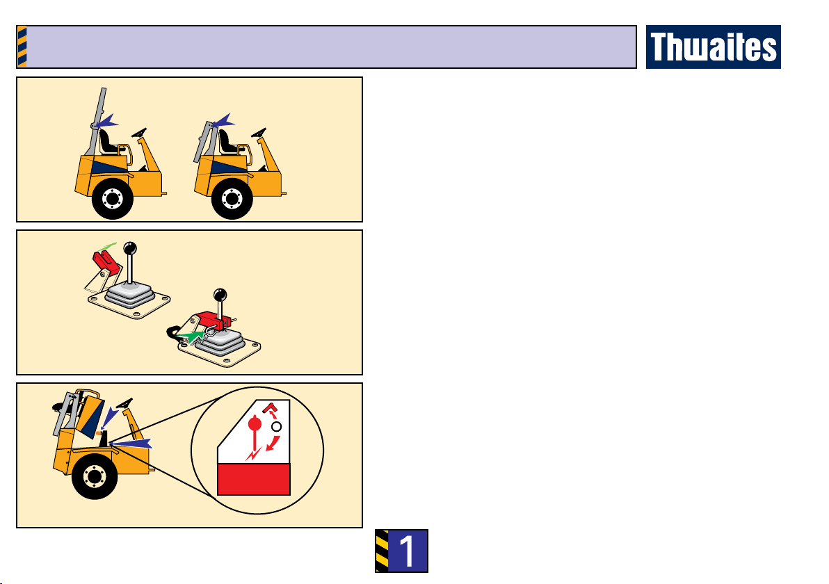
Skip-Rotate lever (Powerswivel and Hi-Swivel models) – left hand
• Tip skip 100 mm (4”) to disengage pivot centring lock
Rotate skip, fully lowered to centre to automatically engage centring lock.
• Push lever to the right to rotate skip to right
• Push lever to the left to rotate skip to left
• An increased engine speed will reduce cycle times
Movement of the skip is disabled if the steering wheel is moved (priority
steering).
Skip-raise lever (Hi-Swivel model) – left hand
• push forward to raise skip
• push backwards to lower skip
1
Complete Checks in Section Before Starting The Engine
Lowering and raising the folding ROPS frame
• Remove linch pins and withdraw frame lock pins
• Lower frame and insert lock pins and linch pins in new position
• Reverse the procedure to raise the frame
• Ensure all pins are secure before driving
Beacon stowage
• Unplug and remove beacon
• Secure beacon on bracket provided beneath bonnet
Battery isolator (Beneath engine cover)
• Turn key anti-clockwise to isolate the battery power supply
Control Functions – in depth
Skip-tip lever lock (if tted)
• Place yoke over tipping lever and secure with linch pin to lock
• Fold back the yoke and secure using linch pin when not in use
2
Complete Checks In Section Before Loading The Machine
How to START and STOP the engine
CAUTION
• Do not use unauthorised starting aids
• Do not tow or bump start
• If a panel light remains on switch off engine (key to
‘O’) and investigate the problem.
WARNING
Do not start the engine unless you are sitting in the
driver’s seat.
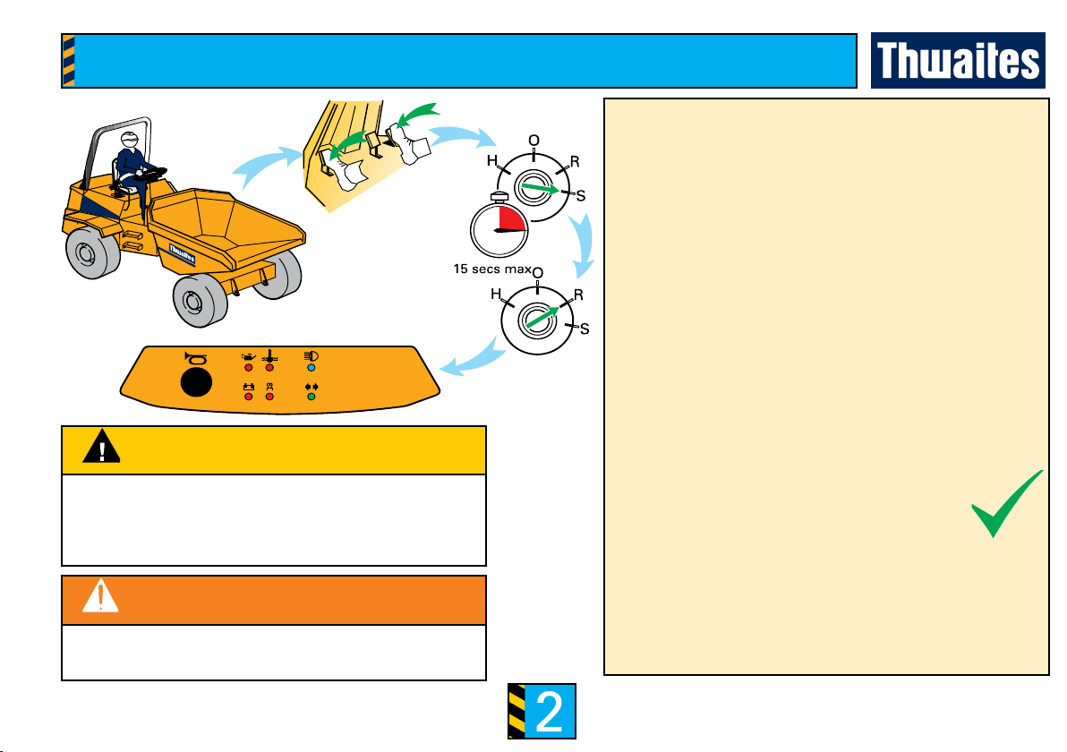
To start the engine
• Set FNR lever to neutral
• Depress accelerator pedal fully and turn the key
clockwise to the start position ‘S’
All panel lights self-test (illuminate) and should extinguish
on start-up.
• Allow the engine to turn for 15 seconds max.
If the engine does not start within 15 seconds, return key
to position ‘O’ and wait 30 seconds before turning to ‘S’
again.
• When the engine res, release key.
(The key will spring back to ‘Run’ position ‘R’).
• Reduce accelerator pedal pressure to prevent over-
revving.
Cold start aid
Turn key to position ‘H’. When panel light extinguishes
start engine (as above).
To Stop The Engine
• Turn key to position ‘O’.
2
Complete Checks In Section Before Loading The Machine
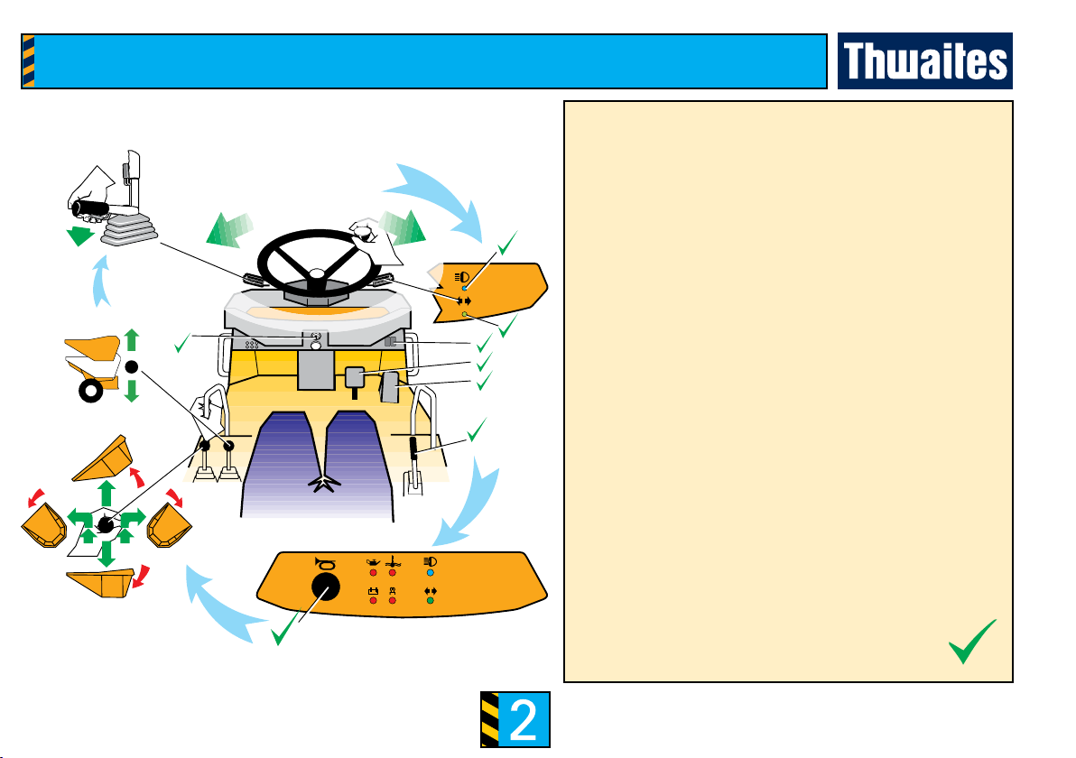
Function Checks - Engine ON
Brakes
• Does the foot brake feel rm?
• Does the hand brake keep the machine stationary
when applied?
Steering
• Rotate the steering wheel clockwise and anti-clockwise
Electrics
• Does the horn sound?
• Does the reverse alarm sound? (Optional).
• Does the beacon ash? (Optional)
• Do all the lights function correctly?
* Side
* Main
* Stop
* Indicators
* Hazards
Skip-tip and skip-rotate lever
• Tip and return skip
• Rotate skip clockwise and anti-clockwise
Skip-raise lever (Hi-Swivel model)
• Raise and lower skip
Preliminary checks

2
Complete Checks In Section Before Loading The Machine
Moving from rest and stopping
• Select forward or reverse
• Select low ratio
• Release hand brake
• Slowly depress accelerator and move away
• Hold steering wheel with both hands
• Remove foot from accelerator pedal
• Brake gently to a halt using foot brake
• Apply hand brake when stationary
Changing speed/direction
• Select high ratio
• The machine must be stationary and the hand brake
must be engaged before changing direction (forward/
reverse).
After operating - park safely
• Always leave skip empty when not in use
• Ensure machine is on rm level ground
• Apply hand brake
• Engage neutral (FNR lever)
• Hydraulic system at rest in a safe condition
• Stop engine and remove key
• Lock engine cover
Driving procedure and safe parking
CAUTION
• Novice operators should always start with forward motion
on clear, level ground
• A low gear should always be selected when a driver is
unfamiliar with machine type

3
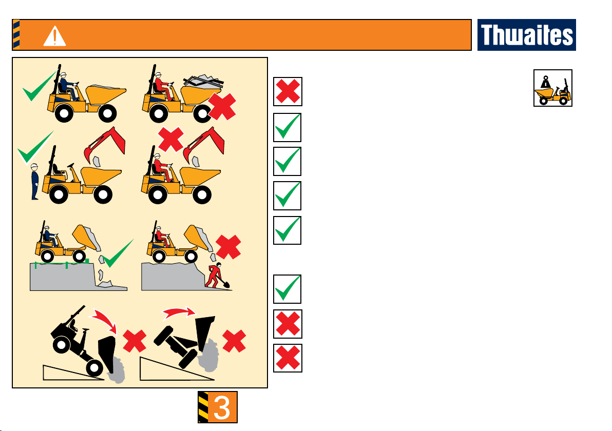
Attention! Section Correct and Incorrect Working Practices
DANGER IMMEDIATE HAZARDS WHICH WILL RESULT IN SEVERE PERSONAL
INJURY OR DEATH
Powerswivel and Hi-Swivel WORKING ON GRADIENTS
DO NOT exceed maximum stated gradients
DO NOT turn across gradients
DO NOT brake suddenly in wet, muddy, icy conditions or when
operating on loose surfaces
DO NOT run downhill with controls in neutral
Travel straight up, down or along a gradient
Keep speed to a minimum and use the foot brake to reduce speed
when travelling down gradients
Always position swivel skip in central lock
Always engage hand brake when stopped on sloping ground to
prevent movement, and, in addition, chock wheels securely when
leaving the machine unattended
DO NOT operate raise mechanism on sloping ground
(Hi swivel model only) - check spirit-level indicator

3
Attention! Section Correct and Incorrect Working Practices
DANGER IMMEDIATE HAZARDS WHICH WILL RESULT IN SEVERE PERSONAL
INJURY OR DEATH
VISIBILITY
Check ahead and behind machine before operation
CRUSH ZONE
Stay clear of articulation area when the engine is running.
WORKING UNDER A RAISED SKIP
Lock skip safety prop during maintenance
Be aware of low-visibility areas when operating
Before operating, sound the horn to warn people in the
immediate area
Never work under an un-propped skip
When using skip safety prop engage skip-tip lever lock
(if tted)
Never operate the machine’s controls when standing on either
side of machine
3
Attention! Section Correct and Incorrect Working Practices
WARNING HAZARDS OR UNSAFE PRACTICES WHICH COULD RESULT IN SEVERE
PERSONAL INJURY OR DEATH
LOADING THE MACHINE
DO NOT exceed machine’s rated capacity
UNLOADING THE MACHINE
Use STOPBOARDS and SUPPORT walls on trenches
Apply hand brake, set transmission to NEUTRAL, turn engine
OFF, disembark the machine and STAND CLEAR
Clear debris from controls
Ensure SAFE STABLE LOW load which allows good visibility.
DO NOT tip skip if load is sticking
DO NOT discharge load when working on sloping ground
Reduce payload if materials being carried are not free owing
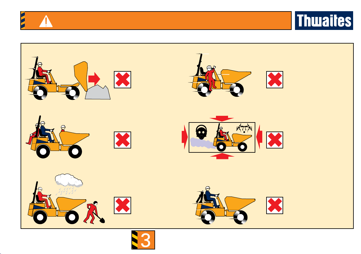
3WARNING HAZARDS OR UNSAFE PRACTICES WHICH COULD RESULT IN SEVERE
PERSONAL INJURY OR DEATH
Attention! Section Correct and Incorrect Working Practices
DRIVING
NEVER dismount from a
moving machine
Site hazards to
avoid: adverse
weather conditions;
icy surfaces; people
DO NOT drive with
the skip tipped
(bulldozing)
DO NOT carry
passengers
Avoid conned work
areas - exhaust fumes
and noise can be a
hazard
DO NOT operate with the
ROPS frame folded

3
Attention! Section Correct and Incorrect Working Practices
WARNING HAZARDS OR UNSAFE PRACTICES WHICH COULD RESULT IN SEVERE
PERSONAL INJURY OR DEATH
TOWING A TRAILER
Place ballast load in skip. This load should be a minimum of
25% of the machine’s rated payload
The gross weight to be towed plus the ballast load MUST
NOT exceed rated payload of machine
DO NOT exceed maximum tow bar pull or vertical load
Towing must not be carried out on sloping ground
Always use a Thwaites-approved towing pin
TRANSPORTATION
Reverse machine slowly onto a suitable trailer
DO NOT drive the machine forwards when loading
1 Apply hand brake
2 Stop engine
3 Chock wheels (To prevent movement)
4 Engage chassis locking bar
5 Secure to trailer
6 Ensure legal load (Height/weight)
3
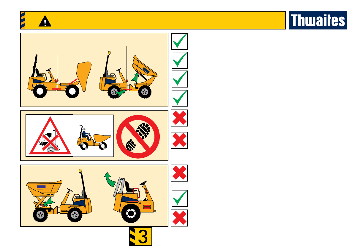
Attention! Section Correct and Incorrect Working Practices
CAUTION HAZARDS OR UNSAFE PRACTICES WHICH COULD RESULT IN MINOR
PERSONAL INJURY OR PRODUCT OR PROPERTY DAMAGE
Hi-Swivel
USING A CRANE TO LIFT THE MACHINE
Tip skip fully forward
Place the locking channel over the tipping ram-rod, then reset
the skip until it is impeded by the channel
Engage chassis locking bar
Lift using centre eye provided
HAND BRAKE
DO NOT apply hand brake if the machine is moving (except in
an emergency)
SLOPING SURFACES
DO NOT step on the rear mudguards’ sloping surfaces
SCISSOR LIFT (HI-SWIVEL MODEL ONLY)
In order to secure the skip in a raised position, place the locking
channel over the lifting-ram rod
Powerswivel
HINGED ROPS
Use grab handles, tread grips (if tted) and steps when
standing on the machine to lower the ROPS frame
Avoid wet surfaces

3
Attention! Section Correct and Incorrect Working Practices
CAUTION HAZARDS OR UNSAFE PRACTICES WHICH COULD RESULT IN MINOR
PERSONAL INJURY OR PRODUCT OR PROPERTY DAMAGE
1
2
CAUTION - MACHINE RECOVERY
In order to tow the machine, the high-pressure circuit at the
hydrostatic pump must be opened.
To open the pump, follow this procedure:
At the left side of the pump below the oor plate there is one high-
pressure control valve at the top, and another at the bottom.
To activate the hydrostatic transmission bypass:
• release lock nut (2);
• screw in grub screw (1) until ush with top of nut (2);
• tighten nut (2).
• Reverse procedure prior to machine being placed back into
service.
TOWING THE MACHINE
• The maximum towing speed of 2 km/h should not be exceeded.
• The towing distance should not exceed 1 km.
This manual suits for next models
3
Table of contents
Other Thwaites Tractor manuals


