Tiancheng Fire Protection Equipment TC-ZJ402 User manual

I. General
TC-ZJ402 wireless signal extender is suitable for domestic wireless alarm system and industrial
wireless alarm system. The signal extender uses advanced wireless transceiver technology, built-in
efficient anti-collision algorithm and can set filtering rules, so that the signal extender can work
reliably in the system. At the same time, the signal extender supports multiple groups of channels,
so that the signal extender can work in complex environments and in the presence of multiple
control panels, realizing mutual non-interference, truly avoiding the collision of channels, and
greatly improving the coverage of wireless networks.
Note: This equipment has been tested and found to comply with the limits for a Class B digital
device, pursuant to part 15 of the FCC rules. These limits are designed to provide reasonable
protection against harmful interference in a residential installation. This equipment generates, uses
and can radiate radio frequency energy and, if not installed and used in accordance with the
instructions, may cause harmful interference to radio communications.
However, there is no guarantee that interference will not occur in a particular installation.If this
equipment does cause harmful interference to radio or television reception, which can be
determined by turning the equipment off and on,the user is encouraged to try to correct the
interference by one or more of the following measures:
--Reorient or relocate the receiving antenna.
--Increase the separation between the equipment and receiver.
--Connect the equipment into an outlet on a circuit different from that to which the receiver is
connected.
--Consult the dealer or an experienced radio/TV technician for help.
Important: You are cautioned that changes or modifications not expressly approved by the party
responsible for compliance could void the user's authority to operate the equipment.
This device complies with part 15 of the FCC Rules. Operation is subject to the following two
conditions: (1) This device may not cause harmful interference, and (2) this device must accept
any interference received, including interference that may cause undesired operation.
Any Changes or modifications not expressly approved by the party responsible for compliance
could void the user's authority to operate the equipment.
II Characteristics.
1. The power adapter is adopted, and the installation is simple and convenient.
2. SI4438 module is adopted, which has strong transmitting power and high receiving sensitivity.
3. It adopts 470Mhz frequency band and FSK coding, which has strong anti-interference ability,

strong diffraction ability and long transmission distance.
4. Using advanced filtering algorithm, filtering rules can be set, which greatly avoids channel
collision.
5. The cover is made of fireproof ABS engineering plastic, which is beautiful, elegant, safe and
durable.
III Technical characteristics.
1. main power supply: rated working voltage DC5V (power adapter).
Backup power supply: lithium battery 3V/2400MAh.
2. Power consumption: monitoring power consumption ≤ 0.9W.
Alarm power consumption ≤ 2.2w.
3. Operation indicator: the operation indicator flashes during normal operation;
Fault indicator: the indicator is always on when the standby power fails;
Communication indicator: the indicator flashes when forwarding information;
4. Communication mode: 470MHz FSK coded bidirectional communication.
5. Wireless transmission power: 19dbm.
6. Communication distance: ≤50m.
7. Service environment: temperature:-10℃ ~+55℃.
Relative humidity ≤95%, non-condensing
Dimensions: 130mm in diameter and 48mm in height.
9. Cover material and color: ABS, white.
IV. Structural features.
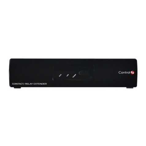
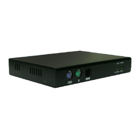
1. The outline diagram of signal extender is shown in Figure 1.
Fig. 1 outline diagram of signal extender.
V. Installation
Note: Before installing the detector, please make sure that the battery polarity is correct and the
detector base is firmly installed.
1. Installation method.
The schematic diagram of the base of the detector is shown in Figure 2. Fix the base with two
self-tapping screws or stick it firmly with 3M glue. After the base is firmly installed, rotate the
bottom of the detector clockwise to align with the base, and then install the detector on the base.

Fig. 2 outline diagram of base.
2. Key points of on-site installation.
The signal extender should be installed at an appropriate position in the wireless network, so that
the signal extender can play the role of a bridge between the control panel and the detector. When
the signal strength is insufficient (signal strength test method, if there is a 5-layer relay, first the
control panel is turned on, the first-layer relay is powered on, press the key twice in a row, observe
the fault light, and after blinking for 3 times, if it is extinguished, it means that the signal is good,
but after 3 seconds, it is extinguished, indicating that the signal is poor and the relay position
needs to be adjusted. And so on to install continuous layer relay), the position of the relay in the
network can be reasonably laid out, so that the relay covers a larger area, and at the same time, the
channel collision caused by too close distance can be avoided.
VI. Test
1. The signal extender must be tested after installation or after regular maintenance.
2. Simulated alarm: in the wireless network of the alarm system, choose any detector that uses
wireless signal extender to forward data, artificially meet the alarm conditions, verify whether the
detector alarms normally and whether the control panel computer displays fire alarm information.
3. Unqualified wireless signal extenders shall be treated as "Common Faults and Repair" and
"Maintenance" during the test, and then tested. If they still fail the test, they shall be returned to
the factory for maintenance.
VII. Use and operation.
1. Signal extender configuration: the signal extender is powered on, enters the normal working
mode, clicks the signal extender button three times in a row, and the signal extender enters the
configuration state. at this time, three indicators of the signal extender flash at the same time. by
operating the signal extender configuration software, parameters such as signal extender filtering
rules, channels and forwarding times can be set. see the TC-ZJ400S signal extender configuration
software manual for details.
2. The signal extender works: when the signal extender works, the running indicators up; when the
data to be forwarded is received, the communication indicators up and the data is forwarded; when
the signal extender is in power failure, the fault indicators up constantly.
VIII Common faults and maintenance.

General faults and their solutions are shown in the following table:
Fault
Cause
Solution
Operation indicator does not
flash after the signal extender
is powered on.
1. The main power of signal
extender is abnormal.
2. The standby power of signal
extender is abnormal.
1. Reconnect the adapter.
2. Check the standby voltage
and reconnect it.
When running, the device
alarms successfully, and the
control panel does not display
the fire alarm.
Poor antenna contact.
Connect the antenna well.
IX. Maintenance.
1. Installation position of signal extender to avoid excessive humidity.
2. To ensure the long-term reliability and accuracy of the signal extender, the wireless
performance should be checked regularly.
3. The free warranty period of this signal extender is one year, with lifetime maintenance.
X. Notes
1. During the normal operation of the wireless system, avoid pressing the signal extender button
continuously, which will cause the signal extender to enter the non-working mode and affect the
wireless network.
Normal connection of.
XI. Random documents and warranty instructions
1. Packing documents: 1) Packing list: 1.
2) Instructions: 1 copy
2. Warranty instructions: Our company is responsible for the maintenance of this product. If any
problems are found, please contact our technical service department in time. Users are not allowed
to do so by themselves.
Disassemble or maintenance, otherwise, the consequences will be at your own risk.
3. Maintenance contact information is as follows:
Yingkou Tiancheng Fire Protection Equipment Co., Ltd.
Address: NO. 11-2 Kechechang Xili, Xishi District, Yingkou Pilot Free Trade Zone (Liaoning)
China
Fax: 0417-4835568
Postcode: 115004
Service Hotline: 400-6930-119
Email: info@tcfiretech.com
Website: www.tcfiretech.com
Table of contents

