TIE AMBITECH STAR-BRAKE User manual

STAR·BRAKE
Motor Starter · Electronic Brake
Instructions

Instructions
Motor Starter • Electronic Brake
CAUTION
Disconnect and lock out power to
Star-Brake Terminals 1, 2 and 3
before servicing.

Table of Contents
1.
INTRODUCTION ...................................................................................................................................1
2.
DESCRIPTION AND APPLICATIONS ..................................................................................................1
3.
SAFETY NOTES .................................................................................................................................. 1
4.
LIMITATIONS........................................................................................................................................1
5.
RATINGS ..............................................................................................................................................2
6.
INSTALLATION ....................................................................................................................................2
6.1
Mounting .......................................................................................................................................................2
6.2
Wiring ............................................................................................................................................................2
6.3
Control Wiring ...............................................................................................................................................2
6.4
Power Wiring ................................................................................................................................................2
6.4.1
Three Phase Motor ..........................................................................................................................2
6.4.2
Single Phase Motor..........................................................................................................................2
7.
ADJUSTMENTS....................................................................................................................................3
7.1
Description of the Adjustments .....................................................................................................................3
7.2
Setting the Adjustments ................................................................................................................................3
7.2.1
Starter Overload .................................................................................................................................... 3
7.2.2
Brake Adjustment.............................................................................................................................3
8.
DESCRIPTION OF BRAKING FUNCTION ...........................................................................................3
8.1
Basic Concept...............................................................................................................................................3
8.2
Detail Description ..........................................................................................................................................4
8.2.1
Sensing ............................................................................................................................................4
8.2.2
Interlock............................................................................................................................................4
8.2.3
Logic and Timing..............................................................................................................................4
8.2.4
DC Power and Control .....................................................................................................................4
9.
IF YOU HAVE A PROBLEM..................................................................................................................4
9.1
Preliminary Checks.......................................................................................................................................4
9.2
Motor Will Not Start.......................................................................................................................................4
9.3
No Braking When Motor is Turned OFF: Braking Contactor Pulls In ..........................................................5
9.4
No Braking When Motor is Turned OFF: Braking Contactor Does Not Pull In .............................................5
9.5
Brake Fuse(s) Blow.......................................................................................................................................5
9.6
BEFORE RETURNING ANY UNIT TO THE FACTORY: .............................................................................5
10.
LIMITED WARRANTY ..........................................................................................................................5
11.
PROCEDURE FOR REPAIRS.……………………………………………………………………………................5

Page 1
1. INTRODUCTION
The
STAR-BRAKE
serves as a complete motor control
system for use with all single speed, single direction
machines. Easy to install and adjust, it has no effect on
normal machine performance, operation, or motor life.
-
FEATURES
-
•
FRICTIONLESS BRAKING
•
TORQUE IS FULLY ADJUSTABLE
•
NO MECHANICAL CONNECTIONS
•
INTERNAL FUSES FOR PROTECTION
•
OVERLOAD PROTECTION
2. DESCRIPTION AND APPLICATIONS
The STAR-BRAKE combines an across-the-line magnetic
starter with an electronic motor brake. The starter section
includes adjustable thermal overload protection. The
electronic brake permits rapid stopping of AC motors by
DC injection. Braking action is smooth, adjustable and
frictionless. Torque and Time adjustments permit
matching the braking rate to almost any machine
requirement.
The
STAR-BRAKE
works with most AC motors where
there is a need for a starter and brake combination.
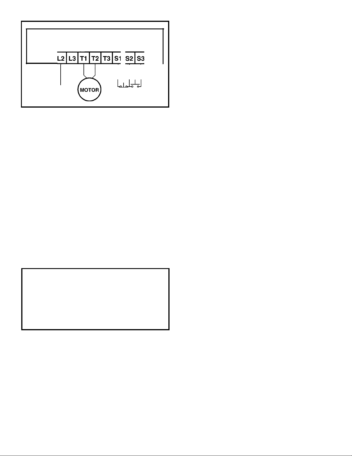
Installation for the standard units simply involves the
connection of six power wires and three control wires.
Standard units are completely satisfactory for most
applications. Ideal for woodworking and metalworking
machines such as saws, lathes, grinders, sanders, etc.
Electronic brakes are useful where coasting is either a
production or a safety problem. However, since electronic
brakes require power to operate and do not provide
holding, they cannot be used as "fail-safe" brakes.
3. SAFETY NOTES
LOCK TOOL OR BLADE SECURELY. Saws and grinders
are often fastened with left-hand thread devices, which
tend to loosen when the machine is stopped too quickly.
Use double nuts, or other positive locking methods to
prevent such loosening. Test for safe operation during
braking and check locking from time to time.
DON'T TAMPER WITH WIRING. Once installed and
adjusted, the
STAR-BRAKE
box cover should be closed
securely. Tampering with the internal parts or manually
operating the magnetic contactors is dangerous, and can
cause damage not covered by the warranty.
POWER LINE INTERRUPTION. The STAR-BRAKE uses AC
line power to achieve its braking action. Thus a power
failure or disconnect, or the opening of a fuse, will simply
let the motor coast to a stop without braking. Do not use
the
STAR-BRAKE
where failure toprovide braking will be a
hazard.
HOLDING AGAINST A LOAD. The STAR-BRAKE cannot
be used as a positive brake against overhauling loads
after the motor stops. In such applications, a positive lock,
a pin, or a separate mechanical brake must be used to
provide for holding at rest. Call the factory for information
on other models if holding is needed.
4. LIMITATIONS
The STAR-BRAKE cannot be used with forward/reverse
or multiple speed systems. It will not work with Universal
Motors, Wound Rotor Motors, Drum Switch Controls, and
Electronic Drive Controllers. For these applications
consult the factory for the appropriate AMBITECH
product.
MOTOR HEATlNG. The heat generated during braking
can be considered equivalent to adding another start
cycle, if the TORQUE control is set very high. Therefore,
high cycle operations may require fan cooling at the
motor. (The
STAR-BRAKE
itself generates very little
heat.)
Although motor heating is rarely a problem, it may be
minimized by using the lowest torque setting that gives
acceptable operation.
IT IS UP TO THE USER TO MAKE SURE THAT THE
MOTOR WILL BE PROTECTED FROM EXCESSIVE
HEAT RISE, WHETHER FROM EXTREMES OF
RUNNING, STARTING OR BRAKING.
POWER OR FUSE FAILURE. Loss of power means loss
of braking, regardless of whether power is disconnected
by a switch, line or internal fuse, circuit breaker, etc. This
also applies to fuses internal to the
STAR-BRAKE,
where
the fuses are intended for the protection of internal
components.
POWER FACTOR CAPACITORS. Power factor
capacitors may NOT be used across a LOAD controlled
by the
STAR-BRAKE.
Move any such capacitors to the
LINE side.
DON'T OPEN POWER TO TERMINALS L1-L2-L3. If
power is removed from these power input terminals during
braking, the brake contactor will open under load which
may damage the
STAR-BRAKE,
and the motor will coast to
a stop.

Page 2
5.
RATINGS
The STAR-BRAKE should be used at its published
horsepower rating. The protective overload is sized for
the nominal motor current, and may not protect a motor of
lower horsepower. For overload rating, see section 7.2.1.
Any application requiring frequent or severe braking, or
operation more often than two stops per minute, may
require a different model STAR-BRAKE.
Applications involving exceptionally high inertia, such as
press flywheels, extractors, etc., may require models with
longer than the standard 15-second maximum braking
time. For information on applications such as these,
please consult the factory or your local sales representa-
tive.
All STAR-BRAKE units may be used in normal ambient
temperatures. The maximum temperature at the hottest
part of the heat sink should not exceed 50 degrees C. At
temperatures below O degrees C, braking levels may
decrease.
STAR-BRAKE units have internal fuses. These are
special, fast-acting, semiconductor fuses. They must be
replaced with the same type as originally supplied.
THE USE OF IMPROPER FUSES IN THE
STAR-8RAA'fWILL VOID THE WARRANTY!!!!
6.
INSTALLATION
6.1
Mounting
The STAR-BRAKE may be mounted in any convenient
location, and in. any orientation, although vertical is
preferable. Keep it away from sources of vibration, dust,
dirt and extremes of temperature. Once mounted, it
normally needs no maintenance.
6.2
Wiring
6.3
Control Wiring
1.
Connect a dry,momentary, normally closed (Stop)
pushbutton between Terminals S1 and S2.
2.
Connect a dry, momentary, normally open (Start)
pushbutton between Terminals S2 and S3.
Note: If a programmable controller is used to control the
Start and Stop function, relay type output modules must
be employed. See section 9.4.
6.4
Power Wiring
WARNING ON THE USE OF
POWER FACTORCAPACITORS
6.4.1
Three Phase Motor
INPUT (LINE POWER) SIDE: Terminal L1, L2, L3
OUTPUT (MOTOR) SIDE: Terminal T1, T2, T3
Figure 6.4.1
6.4.2
Single Phase Motor
3 Phase Wiring
All wiring to the STAR-BRAKE is done to terminals provided.
In general, the wires connected to terminals L1, L2, L3,
T1, T2, T3 must be able to carry the full motor starting and
running current. Wires connected to S1, S2, S3 may be
"control wire" gauge.
Input (Line Power) Side: Terminal L1, Terminal L2
Output (Motor) Side: Terminal T1, Terminal T.2
Note that for a given voltage and horsepower rating, a
single phase machine will draw greater current than the
three-phase equivalent. Be sure not to exceed
either
the
horsepower or current rating of the
DAR-8/iAl(F.
The STAR-BRAKE will be damaged if power factor
or other capacitors are present across the motor
leads. If capacitors are used, they must be placed
on the LINE side.
Be sure to check if the MOTOR IS ROTATING IN
THE PROPER DIRECTION before operating the
machine. If it is not, interchange the wires con-
nected to Terminals T1 and T3.
,
Stop Start
L1
L2
-
L3
STAR-BRAKE
•
ALL WIRING SHOULD CONFORM
WITH NATIONAL AND LOCAL
ELECTRICAL CODES.
•
BE CERTAIN THAT POWER IS TURNED
OFF AND LOCKED OUT, BEFORE
PROCEEDING WITH ANY WIRING!!!

Page 3
DIAL SETTING WITHIN A RANGE OF 5 TO 20
PERCENT OVER THE SETTING. IF THE OVERLOAD .
TRIPS, WAIT 7 MINUTES AND RESET IT.
7.2.2 Brake Adjustment
NOTE:
A red LED indicator on the circuit board is
illuminated during braking.
1. Set TIME control to mid-range
Figure 6.4.2 Single Phase Wiring
7.
ADJUSTMENTS
7.1
Description of the Adjustments
Three adjustment controls are provided within the
llA/l-8/lAKE'.
One, a "Dial" type, is located on the overload
relay, and sets the overload trip current.
The other two controls (located on the printed circuit
board) determine the amount of braking power applied to
the motor (TORQUE), and the length of time this power is
applied (TIME). The controls are single turn and can be
set by means of a small screwdriver. (An insulated
screwdriver is recommended.) Both controls are at their
minimum when set fully counter-clockwise.
DO NOT
FORCE THE ADJUSTMENT PAST THE END STOPS!
Once set for a particular application, the controls should
not have to be re-adjusted.
CAUTION
7.2 Setting the Adjustments
7.2.1 Starter Overload
THE OVERLOAD ADJUSTMENT HAS BEEN SET TO A
NOMINAL FULL LOAD MOTOR AMPERAGE. IT MAY BE
RE-ADJUSTED IF NECESSARY. THE OVERLOAD WILL
TRIP WHEN THE MOTOR CURRENT EXCEEDS THE
2.
Set TORQUE control to minimum without forcing (Full
counter- clockwise.)
3.
Turn main power ON
4.
Turn motor ON. After full speed is reached, turn
motor OFF.
5.
Adjust TORQUE control in 1/8 turn steps to reach
desired safe braking rate. Braking action is indicated
by a slight hum of the motor as well as the red LED
being lit.
6.
Adjust TIME control so that braking hum stops (and
LED goes out) after the motor stops. Note: As the
motor heats up, the winding resistance will increase.
This may require a longer application of the braking
current. Therefore, set the time control either with the
motor hot, or so as to "hang on" for about a second
after stopping a cold motor.
7.
Repeat steps 4 to 6 above, until a satisfactory stop-
ping time is reached. The maximum tolerable stopping
time should be used.
Applying the brake for a longer time than necessary
serves only to increase motor heating.
8. DESCRIPTION OF BRAKING FUNCTION
8.1
Basic Concept
The principle used by the
STAR-BRAKE
is the injection of a
controlled amount of DC (Direct Current) into an AC motor
to achieve braking. The effect in stopping can be
considered completely analogous to that at motor startup.
The DC current in the motor stator sets up a stationary
magnetic field in which the rotor is turning. The interaction
between the rotor and the magnetic field tries to align the
rotor with the stator field. Thus the
STAR-BRAKE
actually
drives the rotor to zero speed.
A further feature is that the retarding torque is proportional
to the field strength, and hence to the braking current. The
braking strength can be set to any desired value by
adjusting the Torque control.
With high torque settings, this brake can loosen
tools by rapid stopping.
Be certain that tool is keyed, double nutted or
locked very tightly.
Test for safe operation during braking, and check
locking from time to time.
L1
L2--
Stop Start
STAR-BRAKE

Page 4
Other parts of the
STAR-BRAKE
serve to control and
coordinate the action of the braking current, to form a
complete braking system. These are described in the
balance of this section.
8.2
Detail Description
8.2.1
Sensing
This is the part of the system that determines when
braking is required. It consists of circuitry which detects
when the motor is
ON
by sensing the current flowing
through the internal interlock to the starter contactor.
When this current is removed (starter contactor is
disengaged) the brake is activated.
Note: leakage current in the magnetic starter control loop
when the starter is disengaged may be interpreted by the
sensor as a motor run condition, not allowing the brake to
pull in.
8.2.2
Interlock
Once an "OFF" condition is determined by the sensor, the
interlock is opened. This prevents the motor from being
re-started while the braking function is in progress. The
interlock will not be re-established until braking has been
completed.
8.2.3
Logic and Timing
This section initiates the flow of DC power after the
braking contactor has been closed; removes the DC
power and opens the braking contactor at the end of
braking; and re-closes the interlock as the last item in the
braking cycle, restoring control to the motor starter.
8.2.4
DC Power and Control
Under control of the Timing section, this block has the
function of setting up the path for the flow of DC current to
the motor, and for rectifying power from the AC input
supply for DC braking.
Rectification is done by means of a "Controlled Rectifier,"
or SCR. This device conducts for a controllable part of
each AC power line cycle. By setting the phase angle
allowed for conduction via the Torque pot, the amount of
DC current produced for braking can be controlled.
The Controlled Rectifier is not turned ON until after the
braking contactor has closed. It is turned OFF before this
contactor is allowed to open. In this way, the contactor is
never called on to switch under load, and the contacts
therefore experience no wear or arcing - even though they
are carrying DC. This is why it is imperative that the
braking cycle be allowed to run to completion in the
normal way.
9. IF YOU HAVE A PROBLEM
9.1
Preliminary Checks
Check for possible damage in shipping, if so, notify the
freight carrier.
No adjustments are provided or required other than those
described in Section 7.
Should a system fail to perform properly, be sure to check
the wiring first. Also, be certain that the power line voltage
is present and correct. (For instance, there should be
equal voltages between any two leads of a three phase
power line, and these should be in the correct nominal
range for the STAR-BRAKE.)
If the system has previously been operating properly, it is
also a good idea to check the fuses, and that the
adjustments of the three controls, TIME, TORQUE and
OVERLOAD have not been tampered with. Note: 230volt
units operated from 208 volts will produce somewhat
lower torque. Consult the factory if this is a problem.
If there is a problem on initial installation, or if the brake
should fail to function properly, the following checks
should be made:
9.2
Motor Will Not Start
1.
Verify that there is normal line voltage across Termi-
nals L1, L2, L3. Note: 230 volt units operated from a
208 volt line may not allow the starter to engage.(208
volt Models are available.)
2.
Verify that the START and STOP switches are wired
properly. AC control voltage should be present across
START switch. When the switch is pressed you
should read ZERO volts. When the START button
and the STOP button are pressed simultaneously, you
should read AC control voltage across the STOP
switch.
3.
Make sure that the overload has not tripped. In case
the overload has tripped, wait 3 to 7 minutes and then
push the reset button located on the top of the over-
load. NOTE: Frequent starting and stopping, (espe-
cially with high inertia motor loads) can cause nui-
sance tripping of the overloads and fuses.
4.
Make sure that the overload adjustment has notbeen
tampered with.

Page 5
9.3 No Braking When Motor Is Turned OFF: 4. Specify all the above, plus the type of application or
Braking Contactor Pulls In use, and the number of phases involved. Be sure to
Supply the unit Serial Number and Model Number
1. Verify that the unit is installed and wired correctly. From the nameplate, and to list all options provided.
2. Check that the TIME and TORQUE adjustments are 5. PACK THE UNIT CAREFULLY, so that there will be
not set too low. no futher damage during shipment.
3. Check for blown fuses in the STAR-BRAKE. 6. Be sure to include your name, address, telephone
Number, purchase order number and the address to
9.4 No Braking When Motor Is Turned OFF: which the repaired unit is to be sent.
Braking Contactor Does Not Pull In
7. When returning any unit include a brief description of
Leakage current may be present in the magnetic the difficulty you are having, as well as the results of
starter control loop. This is common when a program-any tests you have made on it.
mable controller with a solid-state output module is
used to control the Start/Stop function. Replace the 8. Collect shipments will not be accepted.
output modules with relay types, or call the factory fo
assistance. 10. WARRANTY
9.5 Brake Fuse(s) Blow Each BRAKE-PAK is warranted by the factory for one
year to be free from defects in materials and
1. Replace fuses, and try operating at lower braking workmanship. Repairs will be made at the factory,
torque. If fuses do not blow until torque is turned up, on products that are returned postpaid to the factory.
the STAR-BRAKE chosen was probably too small for
the application. The warranty is VOID if the unit has been tampered
with without express permission: if fuses of an
NOTE: Fuses in the STAR-BRAKE are designed to incorrect type or rating have been used; or for any
Protect the internal components. They are of a
Special fast-acting semiconductor-protecting type, and Aside from the above statement of warranty, TIE
MUST be replaced with the same type of equal or Industrial, its agents, employees, dealers and
Lower current rating. THE USE OF INCORRECT distributors assume NO LIABILITY, AND
REPLACEMENT FUSES WILL VOID THE WARR- SPECIFICALLY ASSUME NO LIABILITY FOR ANY
ANTY, AND MAY RESULT IN FURTHER DAMAGE CONSEQUENTIAL DAMAGE to persons or
TO THE EQUIPMENT. property resulting from malfunction, failure to
function, improper application, or improper
2. Power factor capacitors, if used, MUST NOT be operation of these products.
across the load.
No allowance can be made for removal or installation
If there is still a problem, the unit may need factory service. Costs, machine downtime, transportation, etc.
9.6 BEFORE RETURNING ANY UNIT TO THE FACTORY: THE USER ASSUMS ALL APPLICATION RESPONSIBILITY
1. Measure and document the voltage across Terminals 11. PROCEDURE FOR REPAIR
L1, L2, L3.
If a BRAKE-PAK unit needs to be returned
2. Measure and document the voltage across Terminals for repair, create a packing list for the brake
T1, T2, T3. to be returned. This packing list should be on
your company’s letterhead and should state
3. Document the motor operating voltage, current and at a minimum, the model number, serial
horsepower. number and the problem you are experiencing
with the unit. After creating the packing list,
send the brake with the packing list to our
authorized repair center at the following
address:
Ambi-Tech
Attention: Repairs
44810 Vic Wertz Drive
Clinton Township, MI 48036
Table of contents