TiEmme TSol02 User manual

Pag. 1 / 8 0CAR6IN016500
Termoregolatore TSol02
Manuale d’uso
IT
K1 K2 K3 K4
TMAX
MENU
OFF
INTEG.
TP1
P2
TEMP TE ST SET
1 2 3 4 5 6 7 8 9 10 11 12
13 14 15 16
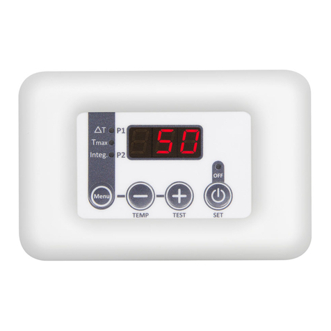
Fig. 1: Aspetto esteriore e Collegamenti Elettrici
Sigla
Morsetti
Dispositivo
Caratteristiche
INGRESSI
T1
15
16
Sonda Collettore
Sensore NTC100K@25°C
Temperatura Max: 200°C Range di Misura: 0÷190°C
T2
13
14
Sonda Boiler Bassa
Sensore NTC100K@25°C
Temperatura Max 100°C Range di Misura: 0÷99°C
T3
11
12
Sonda Boiler Alta
USCITE
P1
3N
4FON
Pompa Solare
Alimentazione 230 Vac: Max 3A 230 Vac
P2
5 Com
6 N.C.
7 N.O.
Integrazione Caldaia
Contatti liberi Max 3A 230 Vac
LINE
1F
2N
Alimentazione di Rete
230 Vac 10% 50 Hz; 2VA Fuse T3,15 A
Dimensioni Meccaniche:
Termoregolatore da Incasso 3 moduli:120 x 80 x 50 mm
Norme Applicate:
EN 60730-1 50081-1 EN 60730-1 A1 50081-2
TiEmme elettronica Marsciano (PG) Italia info@tiemmeelettronica.it
Montaggio ed Installazione deve essere fatto da
personale esperto nel rispetto delle norme vigenti
Posizionare il dispositivo in luogo asciutto e
lontano da fonti di calore
Posizionare le Sonde in modo da leggere
correttamente la temperature
Non accoppiare cavi sonda e cavi di potenza.
Per prolunghe usare cavo da 1,0 mm²
schermato con calza libera lunghezza max. 25 mt.
Il collegamento alla tensione di rete deve essere
fatto solo dopo la installazione e montaggio
T1
P1
P2
T2
T3
P3
Piscina
Pool
P1
T2
T3
T1
P1
T1ice
T3-max
T3Sic
T2Sic
T1Sic
ICE
T
P2
INTEG.
A31
A26
A02
A17
A27
A03
P06
t05
t06
t07
t08
A25
T1Pro
A04
1. ON/OFF
ON/OFF viene effettato tramite la pressione prolungata di K4.Lo stato di OFF è segnalato dal led OFF
2. Funzione ANTIGELO
Se funzione abilitata (P06=1), se la temperatura del Collettore (T1) è minore del termostato A03
La Pompa P1 viene attivata secondo I tempi t05=ON e t06=OFF: Il display visualizza il messaggio ICE
3. Funzione TEST Pompa
Pigiando per 5 secondi K3, la Pompa P1 si attiva per t07 secondi. Pigiando ancora per 5 secondi K3 il tempo
si incrementa di t08 per la funzione Riempimento Impianto. Per fermare la funzione, premere di nuovo K3
4. VISUALIZZAZIONE Temperature
Il display mostra correntemente la temperatura T1 della sonda collettore, i Led indicano lo stato delle uscite.
Tramite il tasto K2 il display visualizza la temperatura delle sonde in sequenza per 5 secondi.

Pag. 2 / 8 0CAR6IN016500
5. Menu PRINCIPALE
Pigiare K1 per entrare nel Menu: Il display visualizza il valore corrente segnalato dal led lampeggiante
Per modificare selezionare il valore da modificare scorrendo la lista con K1, quindi
Tenendo pigiato K4, tramite i tasti K3 e K2 aumentare/diminuire il valore
Per memorizzare aspettare circa 5 secondi o scorrere I valori tramite il tasto K1
Parametri Menu PRINCIPALE
U.M.
Sigla
Min
Default
Max
Set
Termostato Differenziale T12
°C
A31
03
05
30
Termostato Boiler Max T3max
°C
A26
20
70
99
Termostato di Integrazione T3min
°C
A25
05
40
90
6. Menu SECONDARIO
Per entrare nel MENU pigiare contemporaneamente i tasti K2 e K3 per circa 5 secondi
Con K3 o K2 si scorrono le sigle dei parametri: per visualizzare il valore, pigiare K4
Per modificare, tenere pigiato K4 e con i tasti K3 e K2 aumentare/diminuire il valore
Per visualizzare di nuovo la lista dei parametri e memorizzare pigiare il tasto K4
Per uscire e memorizzare, aspettare circa 5 secondi.
Parametri Menu SECONDARIO
U.M.
Sigla
Min
Default
Max
Set
Termostato Sicurezza Collettore T1sic
°C
A02
60
120
180
Termostato Sicurezza Boiler T2sic
°C
A17
60
95
99
Termostato Sicurezza Boiler T3sic
°C
A27
40
95
99
Termostato Protezione Collettore T1Pro
°C
A04
60
140
180
Isteresi Termostato Sicurezza iSic
°C
i 10
1
2
15
Isteresi Termostato Protezione iPro
°C
i 04
1
5
30
Isteresi Termostato Differenziale i12
°C
i 31
1
2
15
Isteresi Termostato Boiler Max iT3max
°C
i 26
1
2
15
Isteresi Termostato Integrazione iT3min
°C
i 25
1
2
15
Abilitazione ANTIGELO
- -
P06
0[off]
0 [off]
1 [on]
Termostato ANTIGELO T1ice
°C
A03
- 5
3
5
Time ON di P1: funzione ANTIGELO
sec
t 05
5
10
60
Time OFF di P1: funzione ANTIGELO
min
t 06
1
20
60
Time ON di P1: funzione TEST
sec
t 07
5
30
60
Time ON di P1: funzione Riempimento
sec
t 08
5
60
255
7. Visualizzazione GUASTI o ALLARMI
1.Lo: T1< 0°C: Sonda interrotta
1.Hi: T1>190°C: Sonda in corto circuito
2.Lo: T2< 0°C: Sonda interrotta
2.Hi: T2> 110°C: Sonda in corto circuito
3.Lo: T3< 0°C: Sonda interrotta
2.Hi: T3> 110°C: Sonda in corto circuito
Se la temperature rilevata da qualsiasi Sonda è superiore al proprio Termostato di Sicurezza
Il display visualizza alternativamente il valore della temperature ed il messaggio Sic
Funzione Silence: Il segnale acustico può essere disattivato per 5 minuti pigiando un tasto qualsiasi.
Se la condizione di allarme permane, il segnale acustico si riattiva

Pag. 3 / 8 0CAR6IN016500
TSol02 Temperature Controller
User Manual
EN
K1 K2 K3 K4
TMAX
MENU
OFF
INTEG.
TP1
P2
TEMP TE ST SET
1 2 3 4 5 6 7 8 9 10 11 12
13 14 15 16
Fig. 1: Exterior Aspect and electrical connections
Code
Morsetti
Dispositivo
Caratteristiche
INPUTS
T1
15
16
Collector Probe
NTC100K@25°C Sensor
Max Temperature: 200°C Measure Range: 0÷190°C
T2
13
14
Low Buffer Probe
NTC100K@25°C Sensor
Max Temperature: 100°C Measure Range: 0÷99°C
T3
11
12
High Buffer Probe
OUTPUTS
P1
3N
4FON
Solar Pump
Supply Voltage 230 Vac: Max 3A 230 Vac
P2
5 Com
6 N.C.
7 N.O.
Boiler Integration
Free Contacts Max 3A 230 Vac
LINE
1F
2N
Main Power Supply
230 Vac 10% 50 Hz; 2VA Fuse T3,15 A
Mechanical Dimensions:
Inbox Controller 3 modules: 120 x 80 x 50 mm
Applied Rules:
EN 60730-1 50081-1 EN 60730-1 A1 50081-2
TiEmme elettronica Marsciano (PG) Italy info@tiemmeelettronica.it
Installation must be carried out by trained
personnel in compliance with regulations in force
Place the device in a dry place away from heat
sources
Make sure to position the Probes properly in
order to obtain correct temperature readings
Do not couple the probe and power cables.
For probe extensions, use 1.0 mm² shielded
cable with free sheath max.25 mt.
The connection to the mains voltage must only
be made after installation and assembly
T1
P1
P2
T2
T3
P3
Piscina
Pool
P1
T2
T3
T1
P1
T1ice
T3-max
T3Sic
T2Sic
T1Sic
ICE
T
P2
INTEG.
A31
A26
A02
A17
A27
A03
P06
t05
t06
t07
t08
A25
T1Pro
A04
1. ON/OFF
To turn ON/OFF the controller, push K4 button for 3 seconds.The OFF state is signaled by the OFF led.
2. ANTIFREEZE Function
In case of P06=1 (enabled function), if the Collector temperature (T1) is lower than A03 thermostat
The P1 pump starts up according the times t05=ON and t06=OFF: the display shows the ICE message
3. Pump TEST Function
By pressing for about 5 seconds K3, the P1 pump starts for t07 seconds. By pressing again K3 for 5 seconds
the time increases by t08 for the Hydraulic Filling. To stop the function push again K3
4. Temperatures DISPLAY
The display currently shows the temperature T1 of the collector probe, the Leds indicate the outputs status.
By pressing K2 button, the display shows the temperature of other probes in sequence for 5 seconds.

Pag. 4 / 8 0CAR6IN016500
5. MAIN Menu
Push K1 to enter into the Menu: the display shows the current value signaled by the blinking led
To modify select the value to modify scrolling the list with K1, then
Keeping K4 pressed, through K3 and K2 increase/decrease the value
To memorize wait for about 5 seconds or scroll the values through K1 button
MAIN Menu Parameters
U.M.
Code
Min
Default
Max
Set
Differential Thermostat T12
°C
A31
03
05
30
Buffer Max Thermostat T3max
°C
A26
20
70
99
Integration Thermostat T3min
°C
A25
05
40
90
6. SECONDARY Menu
To enter into the Menu, press together K2 and K3 buttons for about 5 seconds
Press K3 or K2 to scroll the parameters codes: to visualize the value, press K4
To modify, keeping K4 pressed, through K3 and K2 increase/decrease the value
To memorize and return to the parameter display press K4 button
To exit and memorize, wait for about 5 seconds.
SECONDARY Menu Parameters
U.M.
Code
Min
Default
Max
Set
Collector Safety Thermostat T1sic
°C
A02
60
120
180
Buffer Safety Thermostat T2sic
°C
A17
60
95
99
Buffer Safety Thermostat T3sic
°C
A27
40
95
99
Collector Protection Thermostat T1Pro
°C
A04
60
140
180
Safety Thermostat Hysteresis iSic
°C
i 10
1
2
15
Protection Thermostat Hysteresis iPro
°C
i 04
1
5
30
Differential Thermostat Hysteresis i12
°C
i 31
1
2
15
Max Thermostat Hysteresis on T3 iT3max
°C
i 26
1
2
15
Integration Thermostat Hysteresis iT3min
°C
i 25
1
2
15
ANTIFREEZE Function Enable
- -
P06
0[off]
0 [off]
1 [on]
ANTIFREEZE Thermostat T1ice
°C
A03
- 5
3
5
Time ON of P1: ANTIFREEZE Function
sec
t 05
5
10
60
Time OFF of P1: ANTIFREEZE Function
min
t 06
1
20
60
Time ON of P1: TEST Function
sec
t 07
5
30
60
Time ON of P1: FILLING Function
sec
t 08
5
60
255
7. FAILURES or ALARMS Display
1.Lo: T1< 0°C: Broken Probe
1.Hi: T1> 190°C: Probe in short circuit
2.Lo: T2< 0°C: Broken Probe
2.Hi: T2> 110°C: Probe in short circuit
3.Lo: T3< 0°C: Broken Probe
2.Hi: T3> 110°C: Probe in short circuit
If the temperature read by any probe is higher than that of the Safety Thermostat
The display shows alternatively the temperature value and the message Sic
SILENCE Function: the acoustic signal can be turned off for 5 minutes by pushing any button.
If the alarm condition persists, the acoustic signal restarts.

Pag. 5 / 8 0CAR6IN016500
Termorregulador TSol02
Manual Usuário
K1 K2 K3 K4
TMAX
MENU
OFF
INTEG.
TP1
P2
TEMP TE ST SET
1 2 3 4 5 6 7 8 9 10 11 12
13 14 15 16
Fig. 1: Aparência Externa e Conexões Elétricas
Código
Terminais
Aparelho
Características
INGRESSI
T1
15
16
Sonda Coletor
Sensor NTC100K@25°C
Temperatura Max: 200°C Faixa de Medição: 0÷190°C
T2
13
14
Sonda Tanque Baixo
Sensor NTC100K@25°C
Temperatura Max 100°C Faixa de Medição: 0÷99°C
T3
11
12
Sonda Tanque Alto
USCITE
P1
3N
4FON
Bomba Solar
Alimentação 230 Vac: Max 3A 230 Vac
P2
5 Com
6 N.C.
7 N.O.
Integração Caldeira
Contactos Livres Max 3A 230 Vac
LINE
1F
2N
Alimentação Geral
230 Vac 10% 50 Hz; 2VA Fuse T3,15 A
Dimensões Mecânicas:
Thermoregulator recessado 3 módulos:120x80x50 mm
Normas Aplicadas:
EN 60730-1 50081-1 EN 60730-1 A1 50081-2
TiEmme elettronica Marsciano (PG) Italia info@tiemmeelettronica.it
A montagem e instalação devem ser realizadas
por pessoal especializado em conformidade com
os regulamentos em vigo
Coloque o dispositivo em um local seco, longe
de fontes de calor
Posicione as sondas para ler a temperatura
corretamente
Não acople cabos de sonda e de alimentação
Para extensões, use cabo blindado de 1,0 mm²
com capa livre máx. 25 mt
A ligação à tensão de rede só deve ser feita
após a instalação e montagem
T1
P1
P2
T2
T3
P3
Piscina
Pool
P1
T2
T3
T1
P1
T1ice
T3-max
T3Sic
T2Sic
T1Sic
ICE
T
P2
INTEG.
A31
A26
A02
A17
A27
A03
P06
t05
t06
t07
t08
A25
T1Pro
A04
1. ON/OFF
ON/OFF é realizado ao pressionar e segurar o botão K4.O stato de OFF é sinalizado pelo led OFF
2. Função ANTICONGELANTE
Se a função estiver habilitada (P06=1), se a temperatura do coletor (T1) for menor que o termostato A03
Bompa P1 è acionada de acordo com os tempos t05=ON e t06=OFF: o display mostra mensagem ICE
3. Função TEST Bomba
Ao pressionar K3 por 5 segundos, a Bomba P1 é ativada por t07 segundos. Pressionando K3 novamente
por 5 segundos, o tempo aumenta em t08 para a função de Enchimento. Para parar a função, pressione K3
4. VISUALIZACAO das Temperaturas
O display atualmente mostra a temperatura T1 da sonda do coletor, os LEDs indicam o status das saídas.
Usando a tecla K2, o display mostra a temperatura das sondas em sequência por 5 segundos

Pag. 6 / 8 0CAR6IN016500
5. Menu PRINCIPAL
Pressionar K1 para entrar no Menu: o display mostra o valor atual indicado pelo Led piscando
Para modificar, selecione o valor a ser modificado rolando a lista com K1, a seguir
Mantendo K4 pressionado, use as teclas K3 e K2 para aumentar / diminuir o valor
Para memorizar, espere cerca de 5 segundos ou role pelos valores usando a tecla K1
Parametros Menu PRINCIPAL
U.M.
Código
Min
Default
Max
Set
Termostato Differencial T12
°C
A31
03
05
30
Termostato Tanque Max T3max
°C
A26
20
70
99
Termostato de Integração T3min
°C
A25
05
40
90
6. Menu SECONDARIO
Para entrar no MENU, pressione as teclas K2 e K3 simultaneamente por cerca de 5 segundos
Use K3 ou K2 para percorrer os códigos dos parâmetros: para ver o valor, pressione K4
Para modificar, mantenha K4 pressionado e use as teclas K3 e K2 para aumentar / diminuir o valor
Para exibir a lista de parâmetros novamente e salvar, pressione a tecla K4
Para sair e salvar, espere cerca de 5 segundos
Parametros Menu SECUNDARIO
U.M.
Código
Min
Default
Max
Set
Termostato Segurança Coletor T1sic
°C
A02
60
120
180
Termostato Segurança Tanque T2sic
°C
A17
60
95
99
Termostato Segurança Tanque T3sic
°C
A27
40
95
99
Termostato Proteção Colector T1Pro
°C
A04
60
140
180
Histerese Termostato Segurança iSic
°C
i 10
1
2
15
Histerese Termostato Proteção iPro
°C
i 04
1
5
30
Histerese Termostato Diferencial i12
°C
i 31
1
2
15
Histerese Termostato Tanque Max iT3max
°C
i 26
1
2
15
Histerese Termostato Integração iT3min
°C
i 25
1
2
15
Activação ANTICONGELANTE
- -
P06
0[off]
0 [off]
1 [on]
Termostato ANTICONGELANTE T1ice
°C
A03
- 5
3
5
Time ON di P1: função ANTICONGELANTE
sec
t 05
5
10
60
Time OFF di P1: função ANTICONGELANTE
min
t 06
1
20
60
Time ON di P1: função TEST
sec
t 07
5
30
60
Time ON di P1: função Enchimento
sec
t 08
5
60
255
7. Display FALHAS ou ALARMES
1.Lo: T1< 0°C: Sonda Interrompida
1.Hi: T1>190°C: Sonda curto-circuito
2.Lo: T2< 0°C: Sonda Interrompida
2.Hi: T2> 110°C: Sonda curto-circuito
3.Lo: T3< 0°C: Sonda Interrompida
2.Hi: T3> 110°C: Sonda curto-circuito
Se a leitura da temperatura de qualquer sonda è mais elevada do que o Termostato de Segurança
O display exhibe alternativamente o valor da temperatura e a mensagem Sic
Função Silence: O sinal sonoro pode ser desligado por 5 minutos pressionando qualquer botão.
Se a condição de alarme persistir, o sinal sonoro é reactivado

Pag. 7 / 8 0CAR6IN016500
Termorregulador TSol02
Manual de Usuario
ES
K1 K2 K3 K4
TMAX
MENU
OFF
INTEG.
TP1
P2
TEMP TE ST SET
1 2 3 4 5 6 7 8 9 10 11 12
13 14 15 16
Fig. 1: Apariencia externa y conexiones eléctricas
Código
Terminales
Dispositivo
Caracteristicas
ENTRADAS
T1
15
16
Sonda Colector
Sensor NTC100K@25°C
Temperatura Max: 200°C Rango de medida: 0÷190°C
T2
13
14
Sonda Tanque Bajo
Sensor NTC100K@25°C
Temperatura Max 100°C Rango de medida: 0÷99°C
T3
11
12
Sonda Tanque Alto
SALIDAS
P1
3N
4FON
Bomba Solar
Alimentación 230 Vac:Max 3A 230 Vac
P2
5 Com
6 N.C.
7 N.O.
Integración Caldera
Contactos Libres Max 3A 230 Vac
LINE
1F
2N
Alimentación General
230 Vac 10% 50 Hz; 2VA Fuse T3,15 A
Dimensiones Mecánicas:
Termorregulador empotrable 3 módulos:120x80x50 mm
Reglas aplicadas:
EN 60730-1 50081-1 EN 60730-1 A1 50081-2
TiEmme elettronica Marsciano (PG) Italia info@tiemmeelettronica.it
El montaje debe ser realizado por personal experto
en cumplimiento de la normativa vigente.
Coloque el dispositivo en un lugar seco y alejado
de fuentes de calor
Posicionar las sondas para leer la temperatura
correctamente
No acople los cables de sonda y de alimentación
Para extensiones, utilice cable blindado de 1,0
mm² con vaina libre máx. 25 mt.
La conexión a la tensión de red solo debe
realizarse después de la instalación y el montaje
T1
P1
P2
T2
T3
P3
Piscina
Pool
P1
T2
T3
T1
P1
T1ice
T3-max
T3Sic
T2Sic
T1Sic
ICE
T
P2
INTEG.
A31
A26
A02
A17
A27
A03
P06
t05
t06
t07
t08
A25
T1Pro
A04
1. ON/OFF
ON/OFF se efectúa presionando K4 para un tiempo prolongado. El estado OFF se indica con el LED OFF
2. Función ANTICONGELANTE
Si la función está habilitada (P06=1), si la temperatura del colector (T1) es menor que el termostato A03
La bomba P1 se activa según los tiempos t05=ON y t06=OFF: el display muestra el mensaje ICE
3. FunciónTEST Bomba
Pulsando K3 durante 5 segundos, la bomba P1 se activa durante t07 segundos. Presionando de nuevo K3
durante 5 segundos, el tiempo aumenta en t08 (función de Relleno). Para detener la función, presione K3
4. VISUALIZACIÓN Temperaturas
El display muestra actualmente la temperatura de la sonda T1, los Led indican el estado de las salidas.
Con la tecla K2, el dispèlay muestra la temperatura de las sondas en secuencia durante 5 segundos.

Pag. 8 / 8 0CAR6IN016500
5. Menú PRINCIPAL
Presione K1 para ingresar al Menú: el display muestra el valor actual indicado por el Led parpadeante
Para modificar, seleccione el valor a modificar desplazándose por la lista con K1, luego
Manteniendo K4 presionado, use las teclas K3 y K2 para aumentar / disminuir el valor
Para memorizar, espere unos 5 segundos o desplácese por los valores con la tecla K1
Parámetros Menú PRINCIPAL
U.M.
Código
Min
Default
Max
Set
Termostato Diferencial T12
°C
A31
03
05
30
Termostato Tanque Max T3max
°C
A26
20
70
99
Termostato Integración T3min
°C
A25
05
40
90
6. Menú SECUNDARIO
Para ingresar al MENÚ presione las teclas K2 y K3 simultáneamente durante unos 5 segundos
Utilice K3 o K2 para desplazarse por los códigos de los parámetros: para ver el valor, presione K4
Para modificar, mantenga presionado K4 y use las teclas K3 y K2 para aumentar / disminuir el valor
Para volver a mostrar la lista de parámetros y guardar, presione la tecla K4
Para salir y guardar, espere unos 5 segundos
Parámetros del menú SECUNDARIO
U.M.
Código
Min
Default
Max
Set
Termostato Seguridad Colector T1sic
°C
A02
60
120
180
Termostato Seguridad Tanque T2sic
°C
A17
60
95
99
Termostato Seguridad Tanque T3sic
°C
A27
40
95
99
Termostato Protección Colector T1Pro
°C
A04
60
140
180
Histéresis Termostato seguridad iSic
°C
i 10
1
2
15
Histéresis Termostato Protección iPro
°C
i 04
1
5
30
Histéresis Termostato Diferencial i12
°C
i 31
1
2
15
Histéresis Termostato Tanque Max iT3max
°C
i 26
1
2
15
Histéresis Termostato Integración iT3min
°C
i 25
1
2
15
Habilitación ANTICONGELANTE
- -
P06
0[off]
0 [off]
1 [on]
Termostato ANTICONGELANTE T1ice
°C
A03
- 5
3
5
Time ON di P1: función ANTICONGELANTE
sec
t 05
5
10
60
Time OFF di P1: función ANTICONGELANTE
min
t 06
1
20
60
Time ON di P1: función TEST
sec
t 07
5
30
60
Time ON di P1: función RELLENO
sec
t 08
5
60
255
7. Visualización de FALLAS o ALARMAS
1.Lo: T1< 0°C: Sonda interrumpida
1.Hi: T1>190°C: Sonda en cortocircuito
2.Lo: T2< 0°C: Sonda interrumpida
2.Hi: T2> 110°C: Sonda en cortocircuito
3.Lo: T3< 0°C: Sonda interrumpida
2.Hi: T3> 110°C: Sonda en cortocircuito
Si la temperatura detectada por cualquier sonda es superior a su Termostato de Seguridad
El display muestra alternativamente el valor de temperatura y el mensaje Sic
Función Silence: La señal acústica se puede desactivar durante 5 minutos pulsando cualquier botón.
Si la condición de alarma persiste, la señal acústica se reactivará
Table of contents
Languages:
Other TiEmme Temperature Controllers manuals
Popular Temperature Controllers manuals by other brands
Watlow Electric
Watlow Electric 733 Series Service manual
Renkforce
Renkforce TR-93 operating instructions
Auber Instruments
Auber Instruments WSD-1200GPH quick guide
GIA
GIA GIATSU GIA-KJRP86A1E Installation and operation manual
DMP Electronics
DMP Electronics 1115 installation guide
Esco
Esco SC-20D user manual
Tempco
Tempco TEC-9090 instruction manual
RF Code
RF Code R151 installation guide
Sorel
Sorel STDC1 Installation and operating instructions

2VV
2VV ESSENSSE NEO COMFORT Installation and operation instructions
TREND
TREND T/PI installation instructions
Wavelength Electronics
Wavelength Electronics LDTC2/2 manual
