manuals.online logo
Brands
  1. Home
  2. •
  3. Brands
  4. •
  5. Auber Instruments
  6. •
  7. Temperature Controllers
  8. •
  9. Auber Instruments WSD-1200GPH User manual

Auber Instruments WSD-1200GPH User manual

1
Quick Guide for WSD-1200GPH
Programmable PID Temperature Controller with Dual Probe
*
Version 1.3 (Oct, 2015)
Auber Instruments
5755 North Point Parkway, Suite 99
Alpharetta, GA 30022
770-569-8420
www.auberins.com
Introduction
Thank you for purchasing the Auber WS series temperature controller. We sincerely
appreciate your decision and trust that our machine will meet your expectations in both
the quality of the result and the value of our product. While we are delighted that you may
be anxious to operate the controller for your project, a few minutes of your time reading
through this manual will only serve to enhance your experience in the months and years
ahead. In particular, we urge you to read through the safety warnings below. Although
this plug-and-play controller is very easy to operate, the process involves high
temperature and high wattage appliances and your safety is paramount.
SAFETY WARNINGS
This controller is designed only to be used with devices that have limited power
and their own thermal cut off protection, such as a thermostat or thermal fuse in
case of controller failure.
Do not place any objects on the top of the controller surface as it is used to vent
excess heat during its operation.
The maximum electric current this controller can handle is 13 ampere. For 120
volt AC in US and Canada, this limits the heater power to 1450 watts.
Always place the sensor in the controlled subject when the controller is on. Before
turning on the controller, please make sure the sensor is placed inside the
container to be controlled. Leaving the sensor outside of the solution will form an
open loop operation, and the controller will assume the temperature is low even if
the controlled subject is already very hot. The controller will provide full power to
the heater which will not only overheat the controller, but also damage your
appliance possibly causing a fire.
This controller is designed to control the devices recommended by Auber
*
Patent pending
2
Instruments only. Using it to control a non-recommended device can be
dangerous and cause fire. Auber Instruments is not liable for damages caused by
misuse of the controller. If you are not sure the controller can be used, please
contact Auber Instruments before use.
If an abnormal display or noise is observed, turn the controller off, unplug the
power cord and contact the manufacturer before using it again.
Clean the controller only when it is cool and unplugged.
Do not allow children to operate the controller.
Operating Instructions
1.Description of the controller.
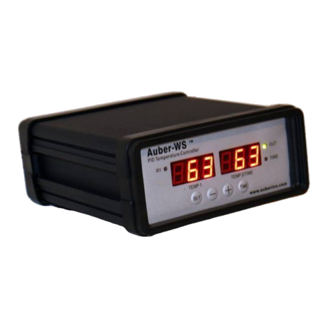
Figure 1. Front Panel
1) TEMP1, Left window - During normal operation, it displays the temperature values
of probe 1. When the high or low limit alarm of probe 1 is on, this window will flash
between the alarm type (AH1orAL1) and the temperature. In the parameter setting
mode, it displays the controller's system parameters.
2) TEMP2/TIME, Right window -During normal operation, it displays the
temperature value of probe 2 (food internal temperature probe) or the time passed
since the controller was powered up. When the high limit alarm of probe 2 is on,
this window will flash between AH2 and the temperature. In the parameter setting
mode, it displays the value of the parameter.
3) Output status indicator - This LED indicates the output status that should be
synchronized with the heater. When it is on (lit), the heater is powered. When it is
off, the heater power is off. When it is flashing, it means the heater is on and off
intermittently to reduce the power output. It should be synchronized with the power
light on the cooking device.
3
4) Smoker generator control output status indicator. When lit, the smoker
generator control output is on. When off, the output is off.
5) Timer status indicator - When lit, right window shows the time passed since
power up. When it is off, right window shows the current temperature detected by
the probe 2.
6) SET Key - For showing current temperature settings, entering parameters setting
mode and confirming various actions taken.
7) “-”Key - To decrement displayed values when controller is in the parameter
setting mode. During normal operation, press it to cancel the alarm.
8) “+” Key - To increment displayed values when controller is in the parameter setting
mode. During normal operation, pressing it will change the left window from
temperature to display which step the program is at.
9) Time Key - Changes the display in the right window between current timer and
temperature values.
Figure 2. Back Panel
2.Connecting and operating the controller
Install the sensor.
(Note: If you ordered wall mount sensor instead of free hanging sensor, please see the
separate instruction in the CD for its installation)
The controller is supplied with two probes. The one with the short tip is for measuring the
cabinet temperature. We name it probe 1. It needs to be plugged to the top sensor jack
4
at the back of the controller. The long probe with a bend at the end is for the meat
internal temperature measurement. It needs to be plugged to the bottom sensor jack at
the back of the controller. The tips of the probes are dropped into the damper hole. Place
a piece of tape on the top of the smoker tower to hold them in place. The tip of probe 1
should be placed close to the food but high enough so that it does not touch the food.
(See Figure 3). The tip of probe 2 is to be inserted into the meat.
Figure 3. Sensor position. Left, the sensor should be placed close to the food but high
enough so that it does not touch the food. Right, hold the sensor in place by a piece of
tape.
For the “Original” and Stainless Steel Bradley smoker, the Temperature Heat Control
Switch on the smoker tower should be slid to the Hi position (Most right).
There are several ways to power up the controller and Bradley Smoker.
Smoke
Generator
Smoker
Tower
Cable B
Cable A
Figure 3.1 Power Cable wiring for Original Bradley Smoker
Cable A: Power cable for Smoker Tower, C14 plug
Cable B: Power cable for smoke generator, NEMA5-15P plug
5
1) Connection for Bradley Original Smoker, with control of the smoker generator.
a) Connecting the controller to the power outlet, you should use the power cord that
came with the Bradley Smoker for connecting the smoker generator to the power outlet.
b) Connecting the controller to the smoker generator. You should use the power cord that
originally was used for connection between the smoker generator and smoker tower.
Figure 4. Connection between the controller and Bradley Original Smoke generator.
6
c) Connecting the controller output to the Bradley Smoker Tower with the power cord that
came with the Auber Controller
Auber
Controller
Smoke
Generator Smoker Tower
Probe 1:
Cabinet Temp
Probe 2:
Internal Temp
Cable A
Cable B
To Power Outlet
Figure 5. Diagram
Figure 6. Back view
7
Figure 7. Connection between the controller and smoker
2) Connection for Bradley Digital Smoker.
For the Bradley Digital Smoker, both controller and smoker generator should be
connected directly to the wall outlet. Connect the controller output with the smoker tower.
Auber
Controller
Smoke
Generator Smoker Tower
Probe 1:
Cabinet Temp
Probe 2:
Internal Temp
Cable C
Cable B
To Power Outlet To Power Outlet
Figure 8. Connection for Bradley Digital Smoker
Cable C is extra 18 AWG power cord, same as Cable B
8
3. Programming the smoking temperature profile.
A total of 6 steps can be programmed with this controller. Each step contains the set
temperature (C-X) and an ending criteria setting (E-X), where “X” is the step number (e.g.
Step 4 temperature is represented by C-4 and step 4 ending criterion is represented by
E-4). The ending criterion determines how the controller finishes the current step and
starts the next step. There are two options for the user, t and F. Set E-X to t if you want
step X to be end by a preset time. Set E-X to “F” if you want step X to end by a preset
temperature of the internal probe.
If you set E-X to “t”, you will be asked to set t-X for the time. Time is defined as the
duration between the last step and the next step. Please make sure the time is long
enough for the heater to heat up the smoker. If the time is set too short, the temperature
may not be able to reach the current step temperature setting, before it jumps to the next
step. The time unit is in hours with 0.1 hour (6 minute) resolution.
If you set E-X to F, you will be asked to set F-X for the temperature of the internal probe.
If all of the E-X are set to t, the controller can operate with only the probe 1 plugged in.
To program the temperature profile, press SET key once. The display will show C-1 at
the left window and temperature setting on the right window for step 1. Use “+” and “-”
keys to change the setting. When finished, press the SET again to confirm the change.
The display will show E-1 on the left window and the ending criterion setting on the right
window. Use “+” and “-”keys to change the settings. When finished, press the SET again
to confirm the change. The left window will display t-1 or F-1 depending whether t or F is
selected for the E-1. The right window will display the setting for t-1 or F-1. Use “+” and “-”
keys to change the setting. When finished, press the SET again to confirm the change.
The display will go the step 2 setting. It will repeat in the same way as the step 1. After
you program enough steps for your recipe, you can program the rest of the steps of E-X
to t and set t-X to zero.
The temperature setting will not be changed if SET is not pressed (confirmed). After
programming the necessary steps for cooking, you can finish programming by pressing
the SET continuously until it passed T-6 and display the current temperature. You can
also leave the controller alone. The display will return to the normal display mode if no
key is pressed within 15 seconds.
The initial program setting for the controller is listed in
Table 1. This program will control the temperature of the cabinet at 120 °F for 2 hours.
Then, change the temperature to 190 °F. It will stay at 190 °F until internal temperature of
the meat reaches 160 °F. Then, the controller will drop the temperature to 130 °F for 30
9
hours, waiting for you to pick up the food. If you set C-3=0 and t-3=0, when meat internal
temperature reaches 160 °F, the controller will shut off the heater, flashing END on both
windows, and turn on the beeping alarm to notify you that cooking is finished.
Table 1. Initial program setting
Step #
Temp (F)
Step #
F or T
Step #
value
C-1
120
E-1
t
t-1
2.0
C-2
190
E-2
F
F-2
160
C-3
130
E-3
t
t-3
30.0
C-4
0
E-4
t
t-4
0.0
C-5
0
E-5
t
t-5
0.0
C-6
0
E-6
t
t-6
0.0
The smoker generator power is controlled by parameters R1 and R2 which can be
accessed by code 166 (see section 7). The generator can be turned on for two steps. R1
is for the first step. R2 is for the second step. e.g. To turn on the smoker generator at step
1 and 3, set R1=1 and R2=3. If you only want to use one step, set either R1 or R2 to 0,
and set the other one to the step you want to turn on the smoker generator. The initial
setting for the controller is to turn on the generator at step 1 only.
4. Check the current step and display the time
To check which step the program is at during cooking, press the “+” Key (8) once. The
left window will show the current step in the form of P-X on. e.g. It will display P-3 if the
controller is at step 3. The display will return to the temperature display automatically
after 8 seconds. To check how long the controller has been running since powered up,
press the Time key (9) once. The Timer status indicator will light. The right window will
show the actual time passed since the controller was last powered up. Please note that
this is the total time, not the time that has passed in the current step. Pressing the Time
key again will switch the display to the internal temperature.
5. Tuning the controller
This controller contains two sets of system parameters that can be changed for different
applications. This controller is shipped with the system parameters set for the Bradley
Smoker. The user should not change these parameters. However, if you feel that
performance is not ideal, you can try to manually tune the system or run the auto-tune
again. For detailed information on how to tune the controller, please read the section 7
and 8 of the main manual.
6. Important consideration for better control results.
The following is a list of things that could affect the results of temperature control.
10
a) The smoker and controller location. The smoker should not be placed directly in the
sun. Direct sun light can heat the smoker to above 140 °F in the summer time, making
controlling the temperature at 140 °F impossible. This is especially the problem for the
Bradley Original Smoker because of its black color. The controller should be placed
away from direct sun light also. Although the controller uses a high intensity LED display,
it will still be difficult to read when sun light is directly shined to its surface. Users should
also avoid exposing the controller to water and rain, which could damage the controller.
b) Low temperature control. The control result for temperatures below 125 °F will not be
as accurate as for higher temperatures when the smoker generator is on. This is
because there are two heaters in the smoker tower. One is the smoker heater controlled
by the PID controller. The other is the heater from the generator that is not controlled.
Our test shows that the heater in the generator itself can raise the temperature of the
smoker tower by 60 °F (2 hours, in the shade with damper open). That means when the
ambient temperature is at 70 °F , the smoker can be heat up to 130 °F in 2 hours by the
heater of the generator (without using the heater in the smoker).
c) Damper position. Keeping the damper open will result in better temperature stability
because more heat loss is created. This is important when the temperature is set below
140 °F. When the damper is closed, the temperature will take longer time to drop if it is
overshot during initial heat up. At higher temperatures, closing the damper will not affect
the performance much because the heat loss from the walls of the tower is increased.
Closing the damper at high temperature will keep the moisture of the food.
d) Temperature uniformity of the smoker tower. Our test shows that when all the shelves
were empty, the temperature inside the smoker tower was fairly uniform except the back
half of the lowest shelf that is close to the heater. Users should avoid placing the sensor
too close to the heater because it does not represent the temperature of the rest area.
When the shelves are filled, temperature variation might depend on how the foods were
placed. The bottom shelf can become hotter if more food is placed in it to block the hot
air from going up.
e) Operating the controller when ambient temperature is below 32 °F (0 °C). The
controller reading is only accurate for temperature ≥ 32 °F (0 °C). In addition, if the
ambient temperature is below 14 °F (-10 °C), the controller will not function because it
can’t read the temperature correctly. In that case, users can warm the sensor by holding
it with their hands. Once the sensor is above 14 °F (-10 °C), it will turn on the heater.
Once the inside of the smoker is heated to above 32 °F , the controller will run by itself.
7. Program the smoker generator on step.
11
The smoker generator is controlled by the parameters R1 and R2. These two parameters
determine which steps to turn on the smoker generator. The smoker generator will stay
on only for the step it is programmed. It will turns off when program goes to the next step.
e.g. When R1=2, and R2=4, the smoker generator will be on during step 2 and 4. R1=0
or R2=0 means that R1 or R2 will not do anything to the smoker. The smoker will not be
turned on if both R1 and R2 are set to 0. R1 and R2 can be accessed through code 166
menu. For details, please read section 7 of the main manual.
8. Program the alarms.
The alarm setting can be accessed by code 188.
Table 2 shows the list of the parameters, their range and initial factory set value
Table 2. List of control parameters and its initial settings under code 188
Symbol
Description
Range
Initial
AH1
Probe 1 high limit alarm
0-200 °C, 0-392 °F
290
AL1
Probe 1 low limit alarm
0-200 °C, 0-392 °F
0
AH2
Probe 2 high limit alarm
0-200 °C, 0-392 °F
200
AST
Step finish alarm
On, OFF
ON
Detail of each parameter.
a) AH1 is the high limit alarm for probe 1. Users can set the temperature so that if the
system is out of control, the buzzer will be turned on. e.g. If AH1 is set to 290, the buzzer
will be on at 291 and off at 290. When the buzzer is on, the left window will flash between
AH1 and the current temperature.
b) AL1 is the low limit alarm for probe 1. e.g. If AL1 is set to 100. The buzzer will be on
when temperature drops to 100. It will be turned off when temperature rises to 101. This
alarm is suppressed when first powered up. It will only function after the temperature has
reached the set point once. When the buzzer is on, the left window will flashing between
AL1 and the current temperature.
c) AH2 is the high limit alarm for the probe 2. If AH2 set to 190, the buzzer will be on at
191 and off at 190. When the buzzer is on, the right widow will flash between AH2 and
the current temperature. When smoking multiple pieces of meat with different
thicknesses, you can put the probe in the thinnest piece first. Set the alarm to the
temperature when meat is ready. It will let you know when it is done. Then, you can move
the probe to the second thinnest pieces and so on. To use this feature, you can set the
ending criteria to time. If you set ending criteria to temperature, you need to set the
ending temperature to be higher than the alarm temperature.
d) AST is the step ending alarm. When AST is turned on, the buzzer will beep 4 times
when each step is finished. It is useful to notify the user the cooking step is finished.
Users can turn it off if no buzzer sound is wanted at the finish of each step.
12
Note: All alarms can be cancelled during beeping by press the “-”key.
For details on how to use code 188 to access these parameters, please read section 7 of
the main manual.
9. Save and recall recipes
This controller can save up to 8 pieces of smoking recipe (programs). Each recipe file
can have up to 6 steps (C-1 to C-6). For convenience, we have pre-named these 8
pieces of recipe files as B1 (beef), B2, C1 (chicken), C2, F1 (fish), F2, P1 (pork), and P2.
These recipe files are all the same except their names, so you can store your special
recipe to any of them. These recipes can be stored in the memory of the controller even
when it is powered off. You can overwrite the exist recipe with a new one.
9.1Save a recipe.
After a program has been entered, the user can save this current program as a recipe for
future use. Under the normal operating mode, press and hold SET key for 2 seconds
until the left window shows “LCK”. The right window will show “0”. Use the “+” or “-”key
to adjust the value to “2” (the passcode for saving the program) and then press SET key
to confirm. Then “SAV” will be shown on the left window and “End” on right window. If
press SET key now, you will exit this mode without overwriting any existing programs.
Use “+” or “-” key to select the name of recipe to which you want to store the program. If
you press “+” (or “-” key) repeatedly, you will see “End”, “b1”, “b2”, “C1”, “C2”, “F1”, “F2”,
“P1”, “P2” one by one. Press the SET key again to store your current program under the
selected recipe name. This process will overwrite the current recipe data to the saved
recipe data.
10. Recall a recipe.
WARNING: You current program will be overwritten by the selected recipe. Please write
it down somewhere if it is important to you. To recall a recipe, press and hold SET key for
2 seconds until the left window shows “LCK” and then release the SET key. The right
window will show “0”. Use “+” key to adjust the number to “1” and then press SET. Then
“rC” (recall) will be shown on the left window and “End” on right window. This can prevent
your current program been accidently overwritten by a recalled program. Use “+” or “-”
key to locate recipe you want to recall. If you press “+” key repeatedly, you will see
“End”, ”b1”, ”b2”, ”C1”, ”C2”, ”F1”, ”F2”, ”P1”, and ”P2” one by one. After you locate the
recipe that you want to recall, press the SET key to select. Current program will be
overwritten by the selected program.
11.Single-step mode
In this mode, the controller will hold temperature at one set value (C-1) continuously as
long as the controller is powered on. Even if the controller is powered off and turned on
13
again, it will resume working in this mode. You do not need to enter any other program
steps in this mode.
To enter the single-step mode, the user need to set the parameter “PrG” to “off”. Under
the normal operating mode, press and hold SET key for 2 seconds until LED display
“LCK” on the left window, and then release the SET key. The display on the right window
will show “0”. Use “+” key to adjust the number to 3 and press SET key again to confirm.
Then “PrG” will be shown on the left window, and “on” or “off” in the right window. Use “+”
or “-” key to toggle between “on” to “off”. Select “off” and press SET key if you want to
enter the single-step mode. Otherwise, select “on” and press SET key to enter the
program mode. The controller will go back to the normal operating mode. To set the
temperature, press SET key once, and the left window will show “C-1”. Use “+” or “-” key
to adjust the temperature in the right window, then press SET to save and exit.
In single-step mode, the save and recall function (Section 9) can still work. But the
change can only be applied to C-1, i.e., you can only store your current set temperature
to the C-1 in a selected recipe, or recall the C-1 temperature from a selected recipe to
the current set temperature. Other data will remain in the memory of controller but is not
accessible under the single-step mode. To exit the single-step mode, you only need to
change the “PrG” value to “on”.
Please note: In older versions, it may show PrG options as “y” or “n”, instead of
“on”, “off”. To enter single-step mode, please select “n”.
12.Examples
a. Store your program as a recipe (Program Mode)
Before you input your program, check the PrG = on (accessed by LCK code “3”). Press
SET briefly, and enter the program below:
C-1=120, E-1=t, t-1=2.0;
C-2= 290, E-2= F, F-2=160;
C-3=130, E-3=t, F-3=30.0.
You can leave the rest of steps as their default values.
To store in program to recipe b1, long press SET key, set LCK=2, choose b1, and press
SET again to confirm and exit. Now the controller is back to the normal operating mode.
It will run on this current program, which has just been saved as recipe b1.
b. Recall a recipe to the current program (Program Mode)
Before you input your program, check the PrG = on (accessed by LCK code “3”). Long
press SET, set LCK=2, choose b1, press set to exit.
Then recipe b1 is recalled back as the current program. The controller is back to the
14
normal operating mode and will start run the current program.
c. Store your program as recipe (Single-step Mode)
Before you input your set temperature, check the PrG = off (accessed by LCK code “3”).
Press SET key once, and then set C-1=150, press set again to confirm and exit. The
controller will go back to the normal operating mode and start running on this single-step
program.
To store current program back to recipe b2, long press SET, set LCK=2, choose b2,
press set to confirm and exit. Now your current program is stored as recipe b2.
d. Recall your recipe to current program (Single-step Mode)
Before you input your set temperature, check the PrG = off (accessed by LCK code “3”).
Long press SET, set LCK=1, choose b2, press set to confirm and exit.
Now the C-1 from the recipe b2 is recalled back to your current program. The controller
will start run at this temperature setting.
e. Advanced example
This example will show you how the PrG mode can affect the saved and current
recipe/program.
1) Set PrG = on, select “b1” recipe:
C-1=120, E-1=t, t-1=2.0;
C-2= 290, E-2= F, F-2=160;
C-3=130, E-3=t, F-3=30.0;
2) Change PrG = off, now the current single-step program is:
C-1: 120.
3) Set current C-1 to 200, then store current program back to recipe b1. Now the b1
recipe is:
C-1: 200.
4) Change PrG = on, current b1 recipe is:
C-1=200, E-1= t, F-1=2.0;
C-2=190, E-2=F, F-2=160;
C-3= 130, E-3=t, F-3=30.0.

This manual suits for next models

1

Other Auber Instruments Temperature Controllers manuals
Auber Instruments SWA-2451B User manual

Auber Instruments

Auber Instruments SWA-2451B User manual

Auber Instruments SYL-1512A User manual

Auber Instruments

Auber Instruments SYL-1512A User manual

Auber Instruments SYL-1614 User manual

Auber Instruments

Auber Instruments SYL-1614 User manual

Auber Instruments WS-1510DPM Administrator Guide

Auber Instruments

Auber Instruments WS-1510DPM Administrator Guide

Auber Instruments SYL-2362A2 User manual

Auber Instruments

Auber Instruments SYL-2362A2 User manual

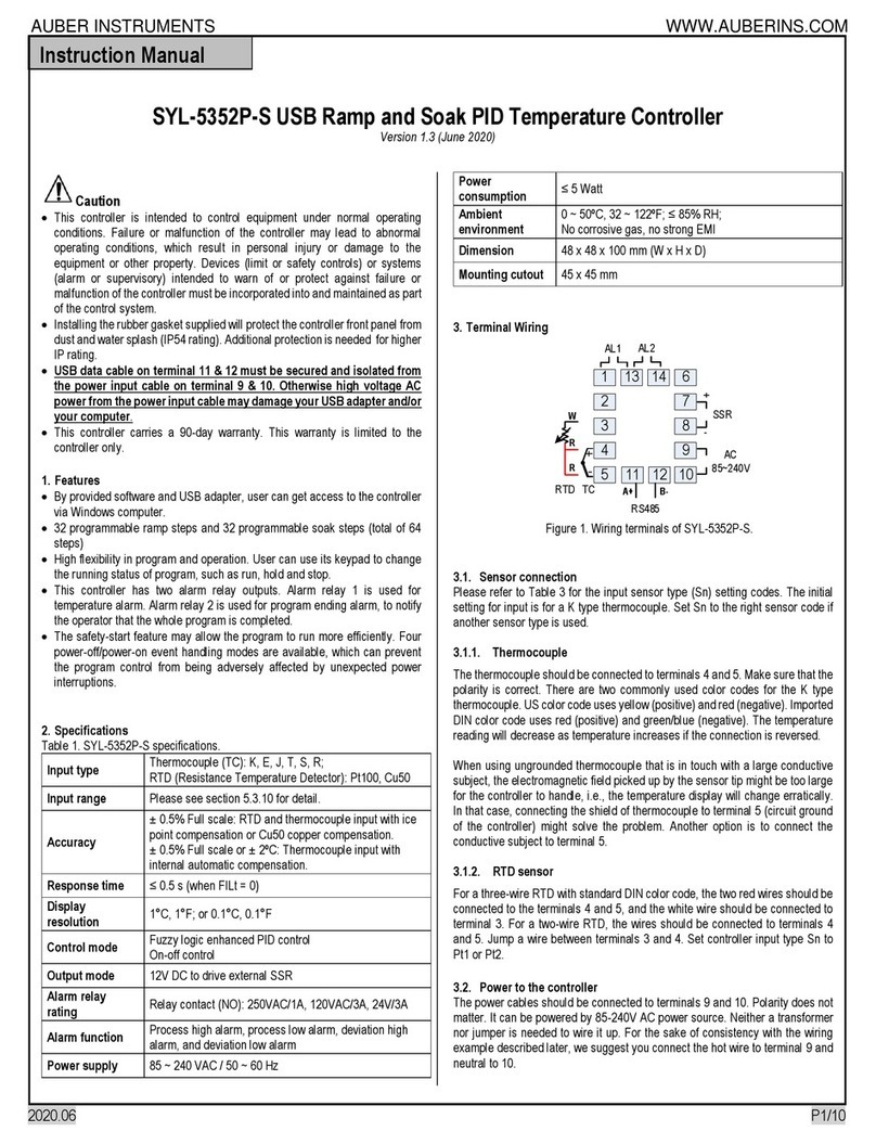
Auber Instruments SYL-5352P-S User manual

Auber Instruments

Auber Instruments SYL-5352P-S User manual

Auber Instruments TH220 User manual

Auber Instruments

Auber Instruments TH220 User manual

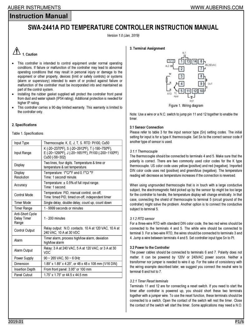
Auber Instruments SWA-2441A User manual

Auber Instruments

Auber Instruments SWA-2441A User manual

Auber Instruments TD120-W Instructions and recipes

Auber Instruments

Auber Instruments TD120-W Instructions and recipes

Auber Instruments WSD-1510GPH User manual

Auber Instruments

Auber Instruments WSD-1510GPH User manual

Auber Instruments SYL-2342 User manual

Auber Instruments

Auber Instruments SYL-2342 User manual

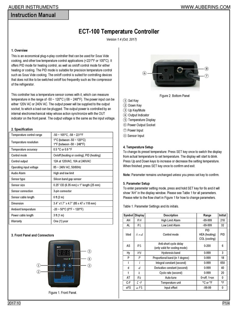
Auber Instruments ECT-100 User manual

Auber Instruments

Auber Instruments ECT-100 User manual

Auber Instruments WSD-1200H User manual

Auber Instruments

Auber Instruments WSD-1200H User manual

Auber Instruments WS-1500C Administrator Guide

Auber Instruments

Auber Instruments WS-1500C Administrator Guide

Auber Instruments WS-1500EB Administrator Guide

Auber Instruments

Auber Instruments WS-1500EB Administrator Guide

Auber Instruments SWA-2441B User manual

Auber Instruments

Auber Instruments SWA-2441B User manual

Auber Instruments WSD-1500H-W Administrator Guide
Auber Instruments

Auber Instruments WSD-1500H-W Administrator Guide

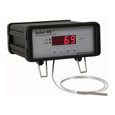
Auber Instruments WS Series Administrator Guide

Auber Instruments

Auber Instruments WS Series Administrator Guide

Auber Instruments WS-1211GPH User manual

Auber Instruments

Auber Instruments WS-1211GPH User manual

Auber Instruments WST-1510H Administrator Guide
Auber Instruments

Auber Instruments WST-1510H Administrator Guide

Auber Instruments WS-1500ES Administrator Guide

Auber Instruments

Auber Instruments WS-1500ES Administrator Guide

Auber Instruments SYL-2372 User manual
Auber Instruments

Auber Instruments SYL-2372 User manual

Auber Instruments SYL-5342P-S User manual

Auber Instruments

Auber Instruments SYL-5342P-S User manual

Auber Instruments SYL-2381-mA User manual

Auber Instruments

Auber Instruments SYL-2381-mA User manual

Popular Temperature Controllers manuals by other brands
Barber-Colman 7EM instruction manual

Barber-Colman

Barber-Colman 7EM instruction manual

Bosch Junkers NTC 10K manual

Bosch

Bosch Junkers NTC 10K manual

Gemo LT102HT quick start guide

Gemo

Gemo LT102HT quick start guide

Raychem HWAT-ECO manual

Raychem

Raychem HWAT-ECO manual

Brookfield TC Series Operator's manual

Brookfield

Brookfield TC Series Operator's manual

Venta AirSense ECO operating instructions

Venta

Venta AirSense ECO operating instructions

Drayton LP20RF Installation & user guide

Drayton

Drayton LP20RF Installation & user guide

Kathrein ESO 005 installation and connection

Kathrein

Kathrein ESO 005 installation and connection

Binder MKF 115 operating manual

Binder

Binder MKF 115 operating manual

CCL ELECTRONICS C3127A user manual

CCL ELECTRONICS

CCL ELECTRONICS C3127A user manual

Adeunis RF sigfox TEMP user guide

Adeunis RF

Adeunis RF sigfox TEMP user guide

Quick-Ohm QC-PC-C01H-100 user manual

Quick-Ohm

Quick-Ohm QC-PC-C01H-100 user manual

i-therm AI-7482D User's operating manual

i-therm

i-therm AI-7482D User's operating manual

Uponor KRS 6 user manual

Uponor

Uponor KRS 6 user manual

Siemens SITRANS TS Series operating instructions

Siemens

Siemens SITRANS TS Series operating instructions

Viega Basic Digital Setpoint Control II Product instructions

Viega

Viega Basic Digital Setpoint Control II Product instructions

dixell Wing XW270L Installation and operating instructions
dixell

dixell Wing XW270L Installation and operating instructions

Yudian AI-218 user manual

Yudian

Yudian AI-218 user manual

manuals.online logo
manuals.online logoBrands
  • About & Mission
  • Contact us
  • Privacy Policy
  • Terms and Conditions

Copyright 2025 Manuals.Online. All Rights Reserved.