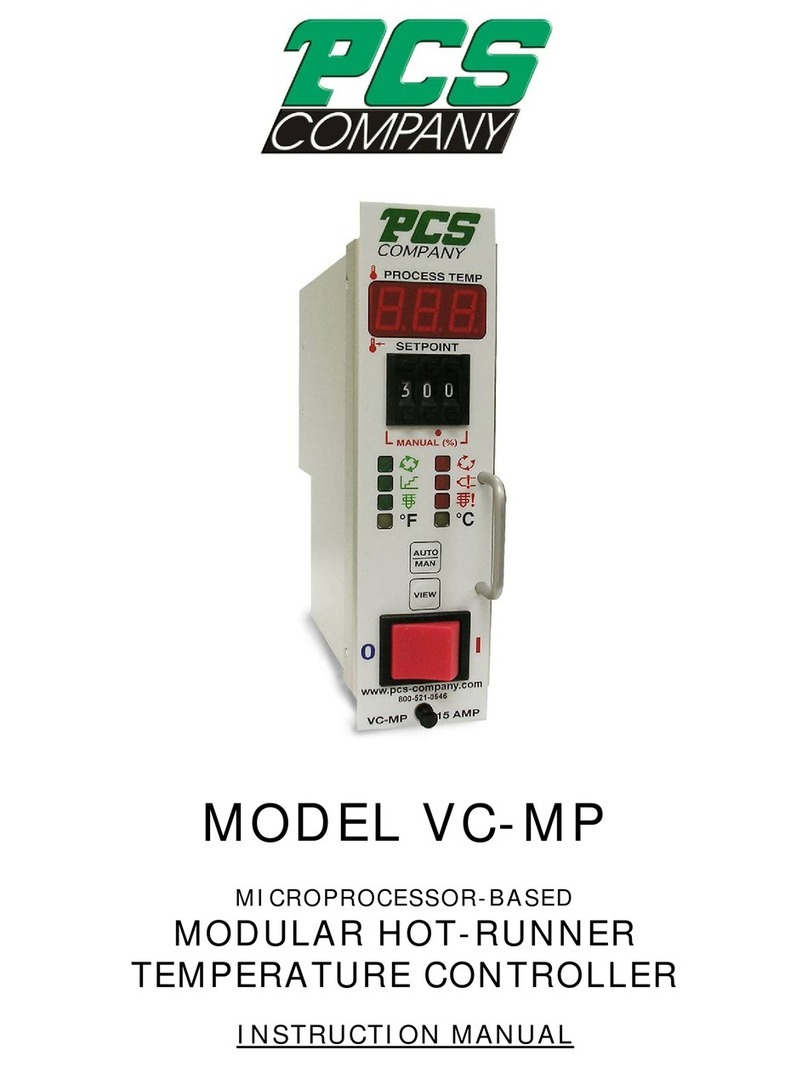
PCS TC50 Series User manual

TC50-6 TC50-12

TC50 Hot Runner Temperature Controller USER MANUAL
-1-
Table of Contents
Chapter 1 Safety Precautions ........................................................ 3
Chapter 2 Features............................................................................ 4
Chapter 3 Appearance and Electronic Control System.............. 5
3.1 Appearance ...................................................................................... 5
3.2 Electronic Layout ........................................................................ 8
3.3 Temperature Control Module................................................ 9
3.4 Bus Board .....................................................................................10
3.5 Output Module .......................................................................... 11
3.6 I/O Board......................................................................................12
3.7 HMI Module ................................................................................13
Chapter 4 Convenient Functions ...................................................14
4.1 Mold Self-Diagnostics..............................................................14
4.2 Thermocouple Abnormal Behavior.....................................14
4.3 Synchronous Heating...............................................................15
4.4 Synchronous Cooling...............................................................15
4.5 Leakage Detection ....................................................................16
Chapter 5 Preparations ...................................................................17
5.1 Connection between TC50 and Mold ................................17
5.2 Parameter Setup........................................................................17
Please read through this user manual carefully before operating the TC50 to avoid damage
to machinery or injury to personnel from improper operation. The controller should also be
placed in a well-ventilated area to ensure the stability of the instrumentation.

TC50 Hot Runner Temperature Controller USER MANUAL
-2-
Chapter 6 HMI Instructions............................................................18
6.1 Monitoring.................................................................................18
6.2 Zone Parameter Setup .........................................................28
6.3 System Setup...........................................................................34
Chapter 7 Troubleshooting...........................................................46
Chapter 8 Connector Wiring ........................................................48
8.1 Connection Type C25............................................................48

TC50 Hot Runner Temperature Controller USER MANUAL
-3-
Chapter 1 Safety Precautions
To ensure the safe and effective operation of the TC50 Multi-Cavity Hot Runner
Temperature Control System, please read through this user manual carefully before
operating the TC50 and follow the warnings and instructions provided. Precautions
before use:
1. Must be installed on a flat, stable floor in a well-ventilated area. Avoid
humid, dusty or high-temperature environments. Installation in the above
environments increases the risk of equipment failure or malfunctions and
may even cause a fire.
2. Pay attention to the type of power supply, voltage and power capacity
before connecting the TC50 to the power supply. Using a power supply that
does not meet specifications will cause serious system damage. When the
main power switch is turned on, if the Over Voltage Source (OVS) light lights
up it means the power supply's voltage is too high (≧280Vac). The main
power switch must be turned off at once and the power distribution verified.
3. Before turning on the main power switch for the TC50, make sure that the
system ground (FG) is properly connected. Improper grounding may lead to
electrocution of personnel or damage to equipment.
4. Check that the TC50 and mold cable connection type are compatible with
each other before connecting. Incompatible connection type poses an
electrocution hazard and will damage equipment.
5. Make sure that the TC50 cooling fan is working at all times. A blockage will
impact on heat dissipation so always keep the fan clean and running.
6. Do not attempt to modify or change this control system without proper
training. Improper modifications may lead to electrocution, injury,
equipment damage, fire and other hazards.
7. Immediately turn off the main power switch if there is any smoke, sparks,
strange smells or odd noises during the operation of the TC50 and have a
technician conduct an inspection. Do no turn on the power again before the
problem is resolved.
8. The TC50 may only be maintained by trained personnel. The main power
switch must be turned off before maintenance. Disassembling the TC50
while the power is connected poses serious electrocution hazard.
9. Storage temperature: -20~70°C/-4~158°F
Operation temperature: -10~50°C/14~122°F
Operation humidity: 0~80%RH (No condensation)

TC50 Hot Runner Temperature Controller USER MANUAL
-4-
1. The power configuration is simple and easy to change, making it compatible
with most electrical systems around the world.
2. Automatic detection of short-circuit protection of heater.
3. Multiple types of module anomaly detection for quick troubleshooting.
4. Simple and easy to use HMI interface.
5. Mold self-diagnostics function that shortens maintenance time by quickly
identifying problems with the control module and molds.
6. If thermocouple abnormality occurs, can choose automatic switching to
Manual, Slave mode to maintain the output, so that the product can be
produced continuously.
7. Synchronous heating function to avoid power being tripped by excessive
loading. This also prevents residue in the tip from becoming carbonized by
high temperatures for extended periods of time and impacting product
quality.
8. Synchronous cooling and standby function for the tip to prevent tip
deformation due to the tip and manifold cooling at different rates.
9. The three-phase of power balance efficiency statistics can provide the basis
for the user to adjust the power load balance to reduce the power loss.
10. The mold leakage detection function can detect the initial mold leakage,
and early detection of leakage can avoid serious damage to the mold and
save huge mold maintenance costs.
Chapter 2 Features

TC50 Hot Runner Temperature Controller USER MANUAL
-5-
TC50 Dimensions
Chapter 3 Appearance and Electronic Control System
3.1 Appearance(Dimensions、Components)

TC50 Hot Runner Temperature Controller USER MANUAL
-6-
TC50_6 ZONES Components

TC50 Hot Runner Temperature Controller USER MANUAL
-7-
TC50_12 ZONES Components

TC50 Hot Runner Temperature Controller USER MANUAL
-8-
3.2 Electronic Layout

TC50 Hot Runner Temperature Controller USER MANUAL
-9-
1. Number of zones controlled: 6 zones.
2. Power Input: 1Φ, 230Vac±10% (overvoltage protection)/24Vdc±5%,
50/60Hz.
3. Power Consumption: 24Vdc/4W
4. Thermocouple: J/K type
5. Temperature Control Range: 0~600°C/32~999°F
6. Control Precision: ±0.25%FS
7. Measurement Precision: ±0.25%FS
8. Fuse: 250Vac/5A, 20mm
9. Output Mode: Zero cross/Phase angle.(compatible output module)
10. Detection Functions: temperature detection/Current detection (compatible
output module)/Overvoltage Protection(≧280Vac start)
11. Temperature Alarm Mode: Higher limit/Lower limit/Standby higher
limit/Standby lower limit/Absolute alarm.
12. Anomaly Detection:
Thermocouple: Short/Break/Reverse.
Heater: Short/Break/Overload.
TRIAC: Short.(compatible output module)
Fuse break.(compatible output module)
13. Communication Mode: RS-485 (Standard MODBUS, Isolated)/
UART (Choose one of two)
14. Communication Rate: 38400/57600
15. ID Setup: DIP switch Setup
16. Storage Temperature: -20~70°C/-4~158°F
17. Operating Temperature: -10~50°C/14~122°F
18. Operation humidity: 0~80%RH (No condensation)
3.3 Temperature Control Module (BAC0200001)

TC50 Hot Runner Temperature Controller USER MANUAL
-10-
3.4 Bus Board (GAA5103003)
1. Slot: 4 (For three output modules and one control module.)
2. Storage Temperature: -20~70°C/-4~158°F
3. Operating Temperature: -10~50°C/14~122°F
4. Operation humidity: 0~80%RH(No condensation)

TC50 Hot Runner Temperature Controller USER MANUAL
-11-
3.5 Output Module (BAC0200000)
1. Number of zones controlled: 2 zones.
2. Power Input: 230Vac±10%/24Vdc±5%, 50/60Hz
3. Power Output: 3450W, 230Vac/15A(per zone)
4. Fuse: Quick response ceramic 500Vac/20A, 30mm
5. Output Mode: Zero cross/Phase angle.(compatible control module)
6. Detection Functions: Current detection, TRIAC Short, Fuse Break(Must be
compatible control module)
7. Storage Temperature: -20~70°C/-4~158°F
8. Operating Temperature: -10~50°C/14~122°F
9. Operation humidity: 0~80%RH(No condensation)

TC50 Hot Runner Temperature Controller USER MANUAL
-12-
3.6 I/O Board (GAA5103006)
1. Power Input: 24Vdc±5% 3W
2. Communication mode:RS-485 (Standard MODBUS,Isolated)
3. Storage Temperature:-20~70°C / -4~158°F
4. Operating Temperature:-10~50°C / 14~122°F
5. Operation humidity:0~80%RH (No condensation)
6. ID:Set 255
7. Communication speed:38400 / 57600
8. Output: 2 zones, dry contact / 3A
9. Input: 2 zones, 24Vdc±5%

TC50 Hot Runner Temperature Controller USER MANUAL
-13-
3.7 HMI Module
1. Screen size: 7"
2. Resolution: 800*480
3. Screen type: TFT Color touch screen (LED Backlight), 65536 color
4. Backlight life: 20,000 hr
5. LCD screen brightness: 400(cd/m2)
6. Touch panel: 4-wire resistive
7. Input voltage: 24 VDC±10%(Isolated)
8. Power consumption: 20 W
9. Operating temperature: 10°C ~50°C
10. Relative humidity: 10%~90%
11. Cooling method: Natural cooling
12. Communication mode: RS-485(Standard MODBUS)

TC50 Hot Runner Temperature Controller USER MANUAL
-14-
Chapter 4 Convenient Functions
4.1 Mold Self-Diagnostics
Due to the complexity of molds, TC50 offers convenient molds self-diagnostics
function to shorten mold maintenance times. This diagnostics function provides the
user with a simple way to troubleshoot most temperature controller and mold
malfunctions.
1. Thermocouple anomaly(Short /Break/Reverse)
2. Heater anomaly(Short/Break/Overload)
3. Fuse anomaly(Break)
4. TRIAC anomaly(Short)
5. Mold wrong wiring
When the temperature control module detects a dangerous or anomalous
situation, it automatically cuts the power output to prevent danger to personnel and
equipment.(Please see 6.3 details)
4.2 Thermocouple Abnormal Behavior
The complex structure and large number of temperature control zones used by
multi-cavity hot runner molds means that thermocouples (especially at the tip) will
inevitably fail during production, forcing a maintenance shutdown that impacts
production.
TC50 offers three loop break modes that allows production to continue and
maintenance to be deferred until the end of the current production run (Please see
6.2 details):
1. Manual: The user can pre-define the appropriate manual output
percentages for each zone. If a thermocouple fails in one zone, TC50 will
automatically switch temperature control for that zone to manual so the
heater will continue to maintain the production temperature and keep
production running.
2. Slave: Multi-cavity molds are mostly used for producing similar products.
Molds for the same product use similar heaters and component structures
as well so the production temperatures are quite similar as well. The user
can identify mold cavities with similar production conditions and set up
master-slave relationships in advance. If the thermocouple for a zone fails
and a master-slave relationship had previously been defined, TC50 will

TC50 Hot Runner Temperature Controller USER MANUAL
-15-
automatically transmit the output percentage from a zone with working
temperature control to the zone with the failed thermocouple. This
maintains more precise temperature control than manual mode for that
zone and allows production to continue.
3. Continue: When the mold is heated to the target temperature (SV) for a few
minutes and thermocouple abnormality occurs. If this function is selected,
the heater can be continuously output, maintaining the steady-state output
ratio before the abnormality to maintain production. However, if this
function is selected, and abnormality occurs when the mold has not been
heated to the target temperature, but the system has not yet obtained the
steady-state output ratio, the output will be reduced to 0, means the
heating operation is stopped.
4.3 Synchronous Heating (Check each heaters type in the mold
matches the selected function before using.)
Multi-cavity molds have lot of heating components (tip, manifold) and consume
more power. When system sets all heaters to start increasing the temperature, the
huge power consumption may often cause the main power switch break due to over
current. There is also a relatively big difference between the heating time for tips and
manifolds. When tips reach the set temperature, they will still need to wait for the
manifolds to reach the set temperature before production beginning. Remaining
plastic in the tip may be degraded by being exposed to high temperature for an
extended period of time and impacting product quality or even resulting in tip
blockages.
To solve the above problems, TC50 has synchronous heating function, While the
manifolds are heated up, if the tips have start ST, tips will first complete the ST
operation with 100% output for a period of time, then output in a smaller percentage
and follow the manifolds temperature, revert to self-control until they are close to the
set temperature. This can solve the problems of power break and plastics
degraded.(Please see 6.3 details)
4.4 Synchronous Cooling (Check each heaters type in the mold
matches the selected function before using.)
Some multi-cavity molds have very sophisticated tip structures. During shutdown
and cooling, the tip will cool at a faster rate than manifolds. When the temperature

TC50 Hot Runner Temperature Controller USER MANUAL
-16-
difference becomes too great, the uneven temperature in the mold body can cause
the tip to warp and in serious cases may even impact tip service life.
TC50 offers a synchronous cooling function during shutdown. The system
automatically keeps all heaters cooling at the same rate to reduce malfunctions
caused by excessive temperature difference. (Please see 6.3 details)
4.5 Leakage Detection (Please refer to the instructions manual for use
to achieve its performance before using this function.)
After hot runner mold is used for a period of time, it may cause the plastic to
leakage from the juncture due to temperature, pressure, tightness change, etc. When
plastic leaks from the mold, the thermocouple and heater may be damaged, it needs
to be repaired or replaced. Sometime the cost of repairs is very huge. If the leakage
can be found at an early stage, it will save a lot of maintenance costs, can also
shorten mold repair time and faster resume production again.
PS: This function is based on the analysis of existing data and cannot replace the
external leakage detection. If the system needs external leakage detection, please
contact us.

TC50 Hot Runner Temperature Controller USER MANUAL
-17-
user must perform the following checks before connecting the TC50 with the mold:
1. Confirm that the operating environment is stable, non-humid, low-dust and
at a suitable temperature.
2. Confirm that the power cable is not damaged and securely connected.
3. Confirm that the TC50 and mold are properly grounded.
4. Check that the TC50 main power switch is set to "OFF".
5. Confirm that the TC50 and the mold are properly connected.
6. Confirm that the wiring between the TC50 and mold are not damaged and
that the connection type matches the way that TC50 and the mold are
connected.
7. Only when all of the above checks have been completed can the user
connect the TC50 and the mold, turn on the power and prepare to
commence production.
5.2 Parameter Setup
After power on, select one zone to set. Start setting the basic parameters after
entering the module setting page:
1. Setting Value: The setting value (SV) for the current zone. Click and select to
set (0~ Temperature limit).
2. TC Type: Thermocouple type (J/K).
3. HT Type: Heater type (Tip/Manifold).
4. Soft Start: Enable heater drying function.
5. ST Mode: Enable Self-tuning mode (No/Once/Every).
6. Trigger Mode: Output trigger mode selection, P.A.(Phase angle)/
Z.C. (Zero cross).
7. Thermocouple anomaly (Loop Break): Operating mode when thermocouple
anomaly occur (stop/manual/slave/continue).
Once the basic parameters have been set, if the parameters for other zones
are the same then copy the parameters as shown in 6.2 details.
Chapter 5 Preparations
5.1 Connection between TC50 and Mold
In order to keep the entire multi-cavity hot runner system working properly, the

TC50 Hot Runner Temperature Controller USER MANUAL
-18-
Zone
Display each zone number and status, click to enter the zone
parameter setting page.(Refer zone parameter settings, see
6.2 details)
6.1 Monitoring
Chapter 6 HMI Instructions

TC50 Hot Runner Temperature Controller USER MANUAL
-19-
Zone Status
1. Heater type
Tip
Manifold
2. Temperature setting.
3. Zone switch.
4. Zone status and alarm message.
Normal Low Alarm
Stop Hi Alarm
Manual ABS Alarm
Slave Module Alarm
Continue
5. Actual temperature
6. Setting temperature
7. Heater output percentage
8. Heater output current
Other manuals for TC50 Series
1
This manual suits for next models
2
Table of contents
Other PCS Temperature Controllers manuals