Tiger CCBTGT-1000N User manual

Chain Hoist
(combined type)
Operating Instructions
WARNING
This hoist should not be installed, operated or maintained by any person who has not read all the
contents
of
these
General
Instructions.
Failure
to
read
and
comply
with
these
instruction
or
any
one of the limitation noted herein can result in serious bodily injury and / or property damage.
MO EL NO: CCBTGT-1000N
Part No.
Part Name Quantity
Part No.
Part Name Quantity
C-1 Label 1 C-17 Chain-End-Fixing Pin 1
C-2 Nut 6 C-18 Load Chain 1
C-4 Gear Cover 1 C-20 heel-side Plate Assembly 1
C-5 Pinion(with Pinion Gear) 2 C-21 Disc Hub 1
C-6 Load Gear 1 C-23 Ratchet Gear with Brake Disc 1
C-7 Pinion Shaft 1 C-24 Pawl Spring 2
C-8 Pinion Shaft asher 1 C-25 Pawl 2
C-9 Gear - Side Plate 1 C-26 Snap Ring for Pawl Pin 2
C-10 Chain Stripper 1 C-27 Ratchet Gear Cover 1
C-11 Load Chain Anchoring 1 C-28 Handwheel 1
C-12 Bottom Hook Assembly 1 C-29 Hand Chain 1
C-12-1
Bottom Hook Pin 1 C-30 asher for Pinion Shaft Nut 1
C-13 Load Chain Guide 2 C-31 Check Nut 1
C-14 Load Sheave 1 C-32 Cutter Pin for Check Nut 1
C-15 Connecting Plate/Connection Kit
2 C-33 Handwheel Cover 1
C-15-1
Connecting Bolt 1

1
IMPORTANT
REMARKS
FOR
OPERATORS
INSPECTION
Do
not
overload
your
chain
hoist.
Do not give the load a sudden take-
off. Take a
breath when the load chain is just taut, and check
for brake action by pulling up and down about
10cm above floor.
Do
not
use
the
chain
with
a
kink.
Do
not
drag
load
against
floor.
Do
not
raise
too
far
or
lower
too
fast.
Do
not
try
to
suspend
a
load
with
two
hoists.
Never
give
a
shock
load
to
a
hoist,
even
i
f
the
distance
is
very
short.
Do
not
wrap
the
load
chain
around
the load.

2
MAINTENANCE
After use, service the hoist before storing it.
Servicing and repairs should only be carried out by qualified, competent ,
and responsible people.
(a) Clean the hoist thoroughly.
(b) Keep the hoist well-lubricated. Oil the load chain and hook shank.
(c) Store the hoist correctly against rain and moisture.
hen the hoist is installed outdoors, exceptional care should be taken regarding
maintenance.
3
INSPECTION
Frequent Inspections:
Visual Inspection by operator or other authorized person, and listening (while hoist
operates) for unusual sounds which may indicate trouble.
Exception:
Brakes require more than audio-visual
inspection. Check
frequently
by
operating
hoist, with and without load, stopping at various positions to test holding power and
observe amount of drift, if any.
To Adjust Brake:(See Fig.1)
A. Fully-tightened position.
B. Slack off slightly form Position A, and insert the cutter pin.
※Replace brake disc if thickness is less than 0.08 inch.
FIGURE 1
4
ALIGNMENT OF GEARS URING REASSEMBLY
●
Model No.: CB-10
Notice the marks " 0 " on the gears, place " 0 " mark face
to sheave on horizontal centerline on right side , place the
other" 0 " mark face to up direction on vertical centerline
on left side as shown. (Figure 2)
FIGURE 2

5
CHAIN
AN
HOOKS
The hooks and load chains are made of special alloy-steels and are precisely
heat-treated. Never weld or heat-treat them again.
(a) Load Chain
The load chains are exceptionally
long-wearing, but wear is unavoidable
and certain conditions will cause wear
and corrosion that will lessen the strength.
Load chains worn beyond the permissible
TABLE 1 CHAIN IMENSIONS
Model o.
Diameter of
Chain ire
Maximum Allowable
Gauge Length
CB-10 10.0mm 21 links=668.0mm
6
TEST
CERTIFICATE
It is hereby certified that this product was
manufactured under our single-unit control
of quality and was passed with strict
inspection in accordance with our
inspection standards.
Capacity
( t )
S. . L.
(kgs)
Test Load
(kgs)
10 10000 15000
(b) Hooks
The hook opening will elongate with
overloads and incorrect hooking.
hen the hook opening is elongated
beyond the permissible limits shown
in the Table 2, it is dangerously
deformed and must be replaced
immediately.
TABLE 2- HOOK THROAT OPENING
Capacity
t
Hook Throat Opening (mm)
e
Normal Discard ≥
10 70 78

Geared Trolley (combined type) Operating Instructions
Model: CCBTGT-1000
WARNING:
BEFORE USING THE TROLLEY, READ CAREFULLEY
THIS MANUAL AND KEEP IT FOR FUTURE NEEDS.
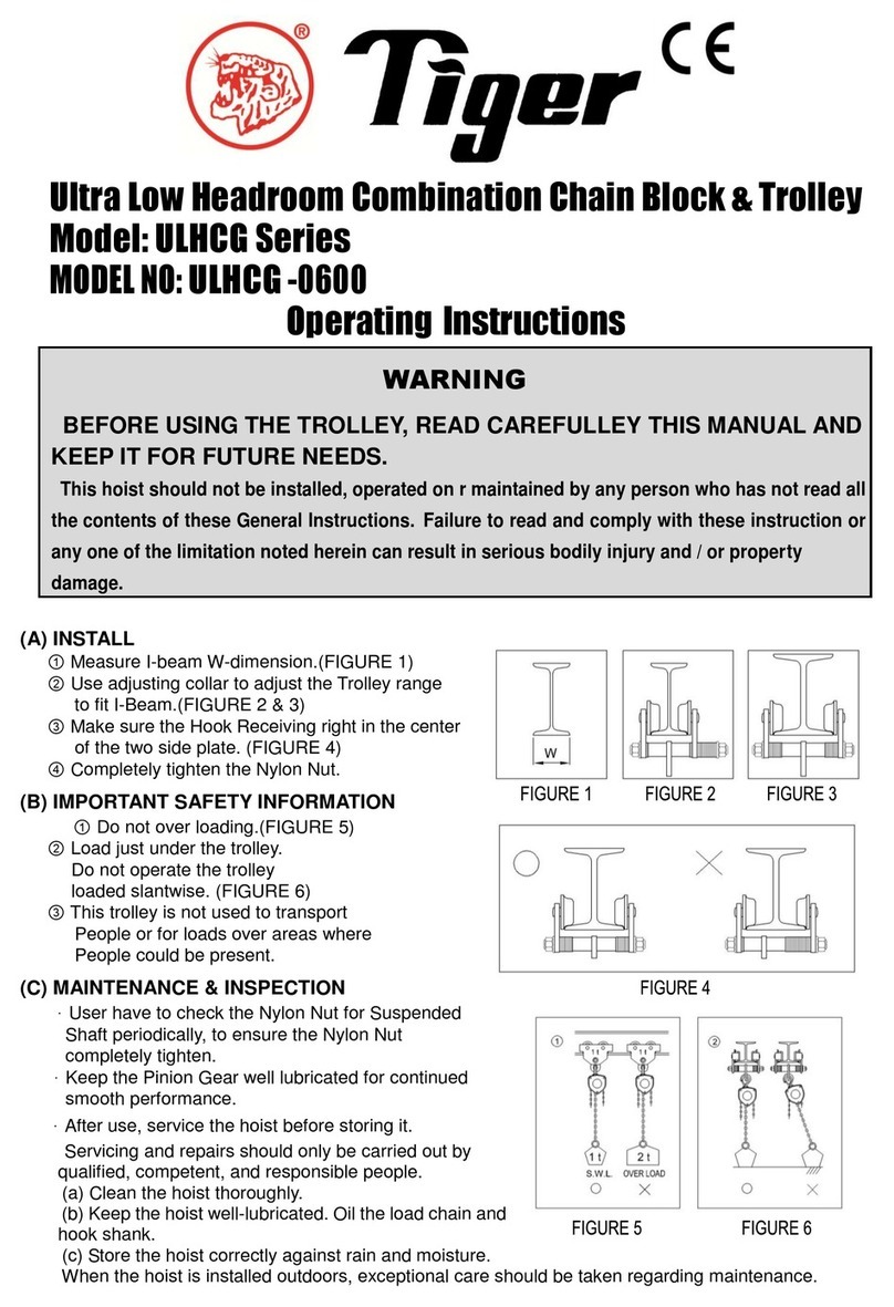
(A) INSTALL
① Measure I-beam W-dimension.(FIGURE 1)
② Use adjusting collar to adjust the Trolley range
to fit I-Beam.(FIGURE 2 & 3)
③ Make sure the Hook Receiving right in the center
of the two side plate. (FIGURE 4)
④ Completely tighten the Nylon Nut.
(B) IMPORTANT SAFETY INFORMATION
① Do not over loading.(FIGURE 5)
② Load just under the trolley.
Do not operate the trolley
loaded slantwise. (FIGURE 6)
③ This trolley is not used to transport
People or for loads over areas where
People could be present.
(C) MAINTENANCE & INSPECTION
.User have to check the Nylon Nut for Suspended
Shaft periodically, to ensure the Nylon Nut
completely tighten.
.Regarding the maintenance of Geared Trolley,
keep the Pinion Gear well lubricated for continued
smooth performance.
(D) SPECIFICATIONS
Type Cap.
Safe
Working
L
oad
Standard I
-
Beam
Min. size
Max. size
Max. Distance
Between
spans
Track widths
Adjustable
Ranges
Min. curve
Radius
ton
kg
mm
M
mm
M
GT-10-TW
10 10000 250 x 125 x 10
600 x 190 x 16
1.5
7.0
125-320
1.5

(E) NOISE INFORMATION
.Operating Conditions: Full loading
.Measurement method: Circling the Trolley at a distance of 1 metre from the surface of the
Trolley and at height of 1.6 metres from the floor.
.The value of the maximum sound pressure is : Plain Trolley – 58 dB
Geared Trolley – 69 Db
(F) EXPLODED VIEW & PARTS LIST:
Quality
Control
Department.
REF. NO.
ART NO.
ART NAME QTY.
REF. NO.
ART NO.
ART NAME QTY.
REF. NO.
ART NO.
ART NAME QTY.
1 -1 Gear Shaft 1
11 -11 lain Side late B 1
22 -22 Washer 4
2 -2 Hand Wheel 1
13 -13 Gear Roller 2
23 -23 Washer 4
3 -3 Shaft Tube 1
14 -14 lain Roller 2
24 -24 Adjusting Collar (short)
44
4 -4 Roller Shaft 2
15 -15 Adjusting Collar (long)
12
25 -25 Nut 1
5 -5 Suspended Shaft
2
16 -16 Cushion Nut M24 4
26 -26 Nut M12 4
6 -6 Roller in 4
17 -17 Ball Bearing 4
27 -27 Nut M24 4
7 -7 Gear Side late A
1
18 -18 Screw 4
28 -28 Nut M30 4
8 -8 Gear Side late B
1
19 -19 Screw 2
29 -29 Washer 2
9 -9 rotection late
1
20 -20 Snap Ring 4
10 -10 lai
n Side late A
1
21 -21 Washer 1
TEST
CERTIFICATE
It is hereby certified that this product was manufactured under
our single-unit control of quality and was passed with strict
inspection in accordance with our inspection standards.
Capacity
(tons)
S. W. L.
(kgs)
Test Load
(kgs)
10 10000 15000
Table of contents
Other Tiger Chain Hoist manuals