TigerStop TigerFence SLR User manual

1
®
TigerFence SLR
Installation Guide
Installation Guide
2017 TigerStop, LLC
February 2017 Mk1
2
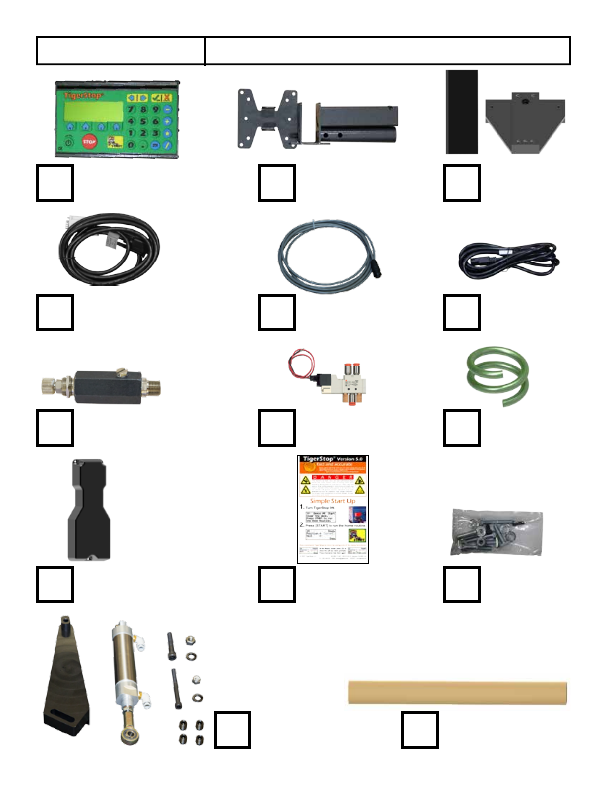
Quick Reference
Cards Nut Pack
Power Cable
Controller Cable
Controller
Stand
Controller
Serial Number
Solenoid Cable
Pneumatic
Tubing
Solenoid ValveRegulator
Drilling
Template
Mounting
Brackets
Nut Pack
Pneumatic
Kit

3
Safety First!
WARNING: Installation of your TigerStop Product must be done by a person trained in the safe
design and installation of automation products, and in the safe operation of power equipment. Ensure
that such installation meets all legally required safety requirements and guidelines, and that proper
guarding and safety devices are provided on all sides of the equipment to preclude unintended access
during operation. Consult with and follow the recommendations of a qualifi ed safety engineer.
WARNING: TigerStop Products are components intended for use in conjunction with potentially
dangerous machinery. The use of TigerStop Products does not make other machinery safe. TigerStop
Products are not intended to substitute, in any manner, for safe operating practices in general, or for
safety features present in other machines designed to make those machines as safe as possible.
TIGERSTOP PRODUCTS, IF USED OR INSTALLED IMPROPERLY, MAY CAUSE PERSONAL
INJURY OR DEATH AND SHOULD ONLY BE OPERATED BY PERSONS TRAINED IN THEIR
SAFE OPERATING PROCEDURES. Illustrations of TigerStop Products in use do not show, and are
not intended to show, all safety features and practices necessary for their safe operation.
GENERAL
WARNINGS
IMPORTANT SAFETY INFORMATION. READ ALL WARNINGS BEFORE OPERATING THIS PRODUCT.
WARNING: TigerStop Products must be installed in accordance with all local, state, and federal
regulations. Only personnel properly trained in the safe design and installation of automation
machinery and related power equipment should install TigerStop Products onto other equipment, to
ensure a safe and proper work station. TigerStop Products should not be operated without proper
training, both in the operation of TigerStop Products, and in the operation of related equipment.
INSTALLATION
WARNINGS
IMPORTANT CAUTION:
The motor box (compartment) contains DC voltage with potentially FATAL amperage. NEVER attempt
any unauthorized actions inside the motor box.
WARNING: Using a TigerStop interconnect does not relieve you of the responsibility for making sure
that your saw or other tool has all the necessary safety equipment in place. All installations must
meet all legally required safety requirements and guidelines. Installation and training should be done
following the recommendations of a qualifi ed safety engineer.
INTERCONNECTS
DANGER: This machine can start, move and stop automatically. Keep hands and loose clothing
clear of moving parts while operating. Moving parts can crush and cut. When used with a saw or
other cutting equipment, bodily injury and death may result if operated without safety guards on
all machines. Do not operate with guards removed. Operators must wear adequate eye and ear
protection.
OPERATION
DANGER! Don’t get pinched by the push feeder. Keep your hands away when in motion!

4
IMPORTANT SAFETY INFORMATION. READ ALL WARNINGS BEFORE OPERATING THIS PRODUCT.
Do not use TigerStop machines in a dangerous environment. Using power tools in damp or wet
locations or in rain can cause shock or electrocution.
Do not operate near fl ammable liquids or in gaseous or explosive atmospheres!
Wear proper apparel, no loose clothes, long hair or jewelry which could get pulled into moving
machinery or materials.
Wear non slip footwear, safety glasses, ear protection and a dust mask.
Use only 3- wire extension cords that have 3-prong grounding type plugs and 3-pole receptacles that
accept the tools plug for 120VAC. Use only 5-wire cords and plugs when using 3 phase.
DO NOT operate this or any machine under the infl uence of drugs or alcohol!
Do not open motor compartment or controller keypad. DC Voltage with potentially FATAL amperage!
Disconnect power before servicing. No user-serviceable parts inside.
No one should operate this machine except for fully qualifi ed personnel.
Read the manual!
Keep the work area clean and well lighted to avoid accidental injury.

5
Table of Contents
Table of Contents
Installation Requirements..............................................................................................6
TigerFence SLR Installation.............................................................................................7
Enable Code..............................................................................................................14
First Power Up...........................................................................................................15
Find the End Limits
Auto Detect
Calibrate
Set Kerf
Set Units
Set Optimizer Settings
Basic TigerFence Functions..........................................................................................20
Entering Decimals
Entering Fractions
Calculator Mode
Jog
Increment
PreSet
Quick Calibration
Working with Part Lists...............................................................................................24
Maintenance Schedule................................................................................................27
6
Installation Requirements
Installation Requirements
Do NOT drill or tap into the TigerStop beam!
Drilling holes into the TigerStop beam may damage the drive system. All fastening or
attachment to the fence beam must be made by inserting T-bolts or T-nuts with washers.
Do NOT over tighten mounting hardware!
It is critical, especially if not using the TigerStop Universal Attachment brackets, that the
bolts are prevented from over tightening and driving into the fence beam. Always use washers.
ALWAYS evenly tighten mounting hardware!
Uneven tightening of mounting hardware can introduce a slight twist or other deformation in the beam.
This will result in inaccurate measurement and premature failure of the drive belt or other components.
NEVER open TigerStop Motor Box!
The motor box compartment contains DC voltage with potentially FATAL amperage.
NEVER attempt unauthorized actions inside the motor box!
110 VAC 15 Amps
208 VAC 20 Amps
240 VAC 20 Amps
TigerFence SLR Power Requirements
TigerFence SLR must have a dedicated circuit. No other equipment should be on the same circuit.
WARNING! Do NOT use a high leg delta circuit to power TigerFence SLR.
If you are not sure what kind of circuit you are using, STOP! Have a qualified electrician confirm the main power circuit.
7
TigerFence SLR Installation
TigerFence SLR Installation
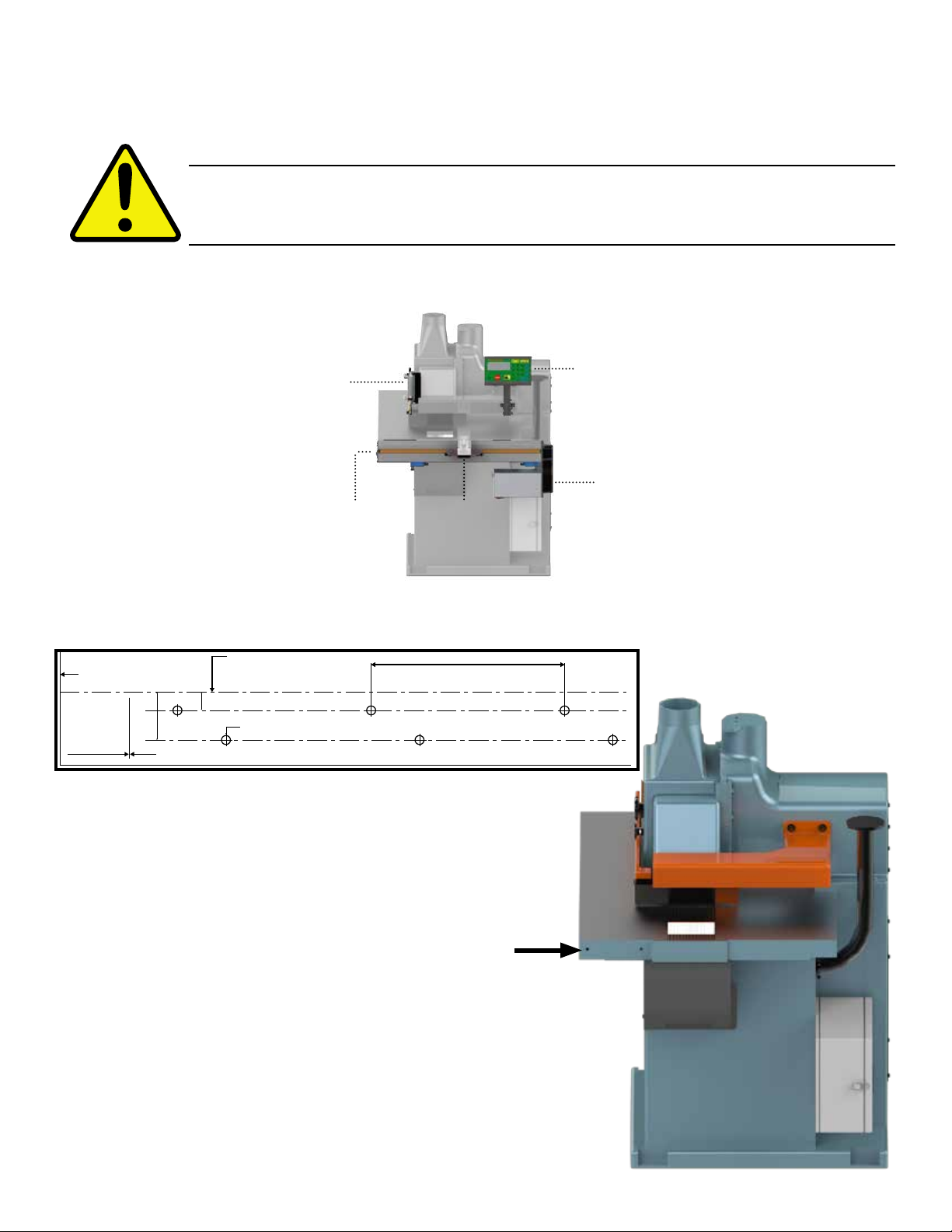
TigerFence SLR Anatomy
Mount TigerFence to Saw
Controller
Motor Box
Carriage
TigerFence
Mounting Slots
(Back)
Cylinder
Bracket
WARNING!
WARNING! Read all instructions before performing installation! NEVER power up
system while motor box is open! ALWAYS lock out/tag out TigerStop machinery
before installing!
Cutting Line - Edge of Saw Blade
Fold Along This Line
Maximum distance between holes on top line not more than 8”
End of TigerFence beam is here - DO NOT POSITION CLOSER TO SAW BLADE
OR SEVERE DAMAGE TO YOUR MACHINE CAN OCCUR!
Mark this line
with center
punches or
scribe.
2”
3/4”
All holes 3/8” - 9.5mm Diameter
8” 203mm
TigerFence Drilling Template
(Shipped in cardboard tube)
1. Remove the existing rip fence from the saw.
Note: Set the fence and fence mounting bolts aside to be
used later.
2. Lay the drilling template over the saw table
and drill the mounting holes into the saw
table and the spacer blocks, as shown on the
template.
Fence
Removed

8
Lock Washer
3. Attach TigerFence SLR to the table using the spacers and
supplied hardware.
Note: Ensure the TigerFence SLR is flush with the saw table top.
Mount Fence to TigerFence
Fence Square Adjustment Screws

9
Mount Anti-Kickback Teeth Control
Drill & Tap
4. Attach your existing ripping fence to
the TigerFence SLR fence bracket.
Note: You may need to drill the existing rip fence.
10
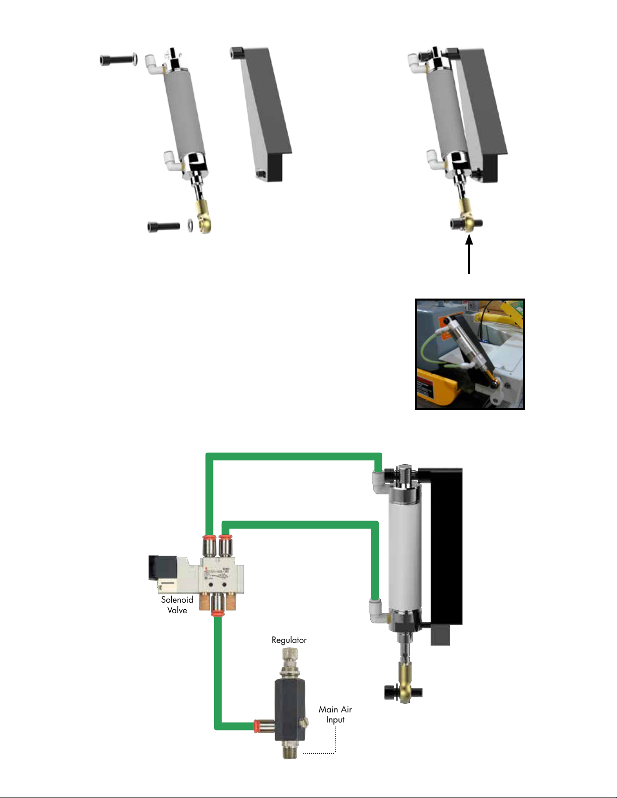
Connect to anti kick back lever
Plumb Pneumatics
Main Air
Input
Regulator
Solenoid
Valve
Anti Kick Back
Cylinder

11
Install Controller Stand
1. 2. 3.
4. 5. 6.
7.
8.
9.

12
End Sensors
Set Range of Movement by Adjusting End Sensors
Loosen & Move
Note: Attach the controller stand
anywhere that is convenient for
the machine operator.
13
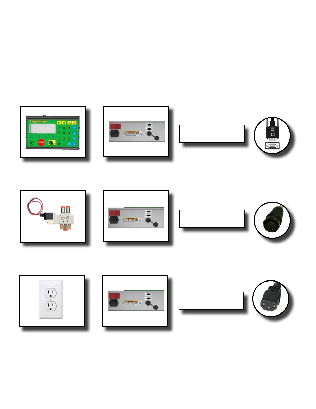
Final Connections
Final Connections
Solenoid TigerStop Motor Box 6 Pin
Solenoid Cable
Power Outlet TigerStop Motor Box Power Cable
Black TigerStop
Power Cable
Controller TigerStop Motor Box 15 Pin
White End (Motor Box)
Black End (Controller)
Controller Cable

14
Enable Code
Enable Code
Your new TigerFence will not function until you enter the TigerStop enable code, which is supplied by
TigerStop Customer Service.
The enable code notifies TigerStop, LLC when your new TigerFence is about to be put into service. This
lets us start the warranty on the exact day you turn it on. The enable code also allows TigerStop to turn
on your TigerStop Dynamic Optimization upgrade.
How to Enable TigerStop
1. Fill out the TigerStop Warranty Registration sheet that is shipped
with your TigerFence controller.
Fax or email the registration to;
(360) 260-0755
You may also register your warranty by phone;
TigerStop Customer Service
(360) 254-0661
TigerStop Customer Service will contact you by phone to give you the
enable code, within the hour during regular business hours, Monday
through Friday 6:00 am - 4:00 pm PST.
2. When you have received your enable code, power up TigerFence using the power switch on the
motor box.
3. TigerFence will ask you to enter your enable code. Enter the code and press .
Your TigerFence has now been enabled.
Enabling Dynamic Optimization
The Dynamic Optimization enable code upgrade is necessary to use TigerFence to its fullest potential.
TigerFence can run an optimizing algorithm that will find the mathematically perfect way to cut your
material. This can decrease material waste by up to 40%.
Ask TigerStop Customer Service about Dynamic Optimization!

15
First Power Up
First Power Up
After entering the enable code, TigerFence will ask to run the ‘Home Routine’.
Home Routine Explained
Every time TigerFence is powered up, it performs the ‘Home Routine’. The home routine is a 3 step
process where TigerFence will move to its farthest possible position.
1. Press
START
to run the Home Routine.
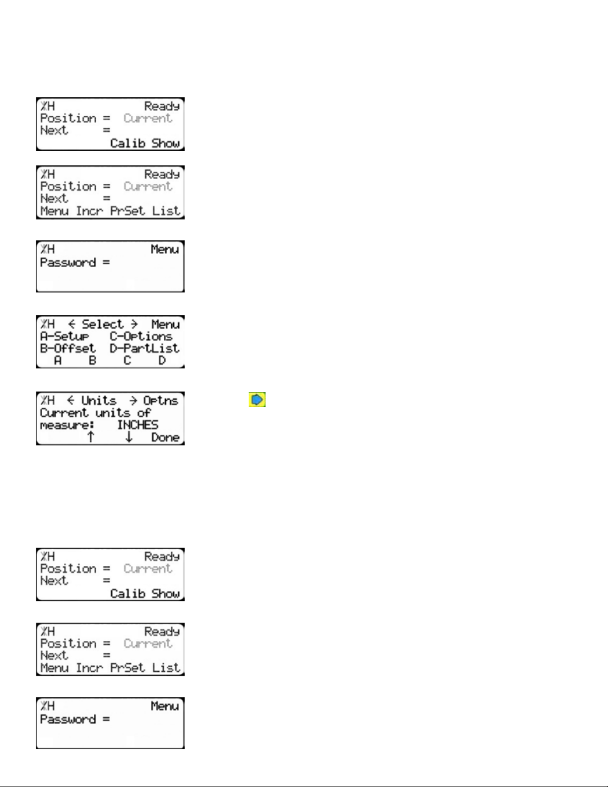
2. When movement stops, TigerStop will display the Ready Screen.
The Ready Screen is the starting point for all TigerStop functions. Let’s take a look at the screen, line by
line.
Line 1 displays the “heartbeat”. The heartbeat is a line that rotates and
lets you know that TigerFence is functioning normally. The letter next
to the heartbeat is the drive indicator. This tells you what the motor is
doing.
Drive Indicator Meaning
H Holding Still
A Accelerating
C Moving at Constant Speed
D Decelerating
W Waiting
S Stopping
T Waiting for Text Entry
X E-stop Error
N Communication Error
Line 2 shows the current position of TigerFence. The position will show
with ‘in’ when in inches mode and ‘mm’ when in metric mode.

16
Line 3 shows the next position of TigerFence. This is where user input is
shown.
Line 4 displays the soft key prompts. These prompts tell you what the
soft key button below it does. These can change when you access
different screens.
The Find end limits routine will make TigerFence physically move between the two end sensors and will
automatically set the minimum and maximum limits.
Find the End Limits
1. From the Ready Screen, press the [Show] soft key to show the menu
options.
2. Press the [Menu] soft key to display the Menu Select screen.
3. TigerFence requires a password to access all menu options. Enter
your TigerFence password and press .
Note: By default, the TigerFence password is set to the serial number.
4. At the Menu Select screen, press the [Setup] soft key to access the
Setup Menu.
5. Press to scroll through the settings. Stop when you see FindLim.
6. Press [Start] to run the Find End Limit routine.
Note: Ensure TigerFence can move its entire length without obstruction. TigerFence
will move once
START
is pressed.
When TigerFence has stopped moving, continue to the next set of instructions.
Auto Detect
1. Press to scroll through the settings until you get to the Auto
detect setting.

17
2. Follow the prompts on screen to detect your Interconnect Kit.
Calibrate TigerStop
1. Press to scroll through the settings until you get to the Calib
setting.
Set Kerf
If the tool you have installed TigerStop to is a cutting tool, you will need to set the Kerf setting. The kerf
is the measure of how much material is destroyed by the saw blade during a cut.
1. From the Ready Screen, press the [Show] soft key to show the menu
options.
2. Press the [Menu] soft key to display the Menu Select screen.
3. TigerFence requires a password to access all menu options. Enter
your TigerFence password and press .
Note: By default, the TigerFence password is set to the serial number.
4. At the Menu Select screen, press the [Setup] soft key to access the
Setup menu.
5. Press to scroll through the settings. Stop when you get to the
Kerf setting.
To measure kerf...
1. Rip a sample piece and measure it with a caliper. Record your measurement.
2. Rip this piece in half.
3. Put the two pieces together as if they were one piece and re-measure with a caliper.
4. The difference between the measurement on step 1 and the measurement on step 3 will be your Kerf
value.
5. Enter your Kerf value and press the [Done] soft key to save the parameter.
Note: It is important to check and reset the Kerf every time the saw blade is changed.
2. Measure how far the TigerStop is from your tool’s zero point.
3. Enter this measurement and press the [Done] soft key.
Note: TigerFence has been calibrated and you will be taken back to the Ready Screen.
18
2. Press the [Menu] soft key to display the Menu Select screen.
3. TigerFence requires a password to access all menu options. Enter
your TigerFence password and press [=].
Note: By default, the TigerFence password is set to the serial number.
4. At the Menu Select screen, press the [Options] soft key to access the
Options menu.
5. Press to scroll through the settings. Stop when you get to Units.
6. Press [B] to toggle between inches and metric.
7. Press the [Done] soft key when finished.
Set Optimizer Settings
TigerStops Dynamic Optimizer is tuned from the factory to give the best overall material yield.
However, the optimizer can be configured differently if you have different requirements.
1. From the Ready Screen, press the [Show] soft key to show the menu
options.
2. Press the [Menu] soft key to display the Menu Select screen.
3. TigerFence requires a password to access all menu options. Enter
your TigerFence password and press [=].
Note: By default, the TigerFence password is set to the serial number.
Set Units
TigerFence can display its position in inches or metric. If you do not wish to change the units, skip this
step.
1. From the Ready Screen, press the [Show] soft key to show the menu
options.
19
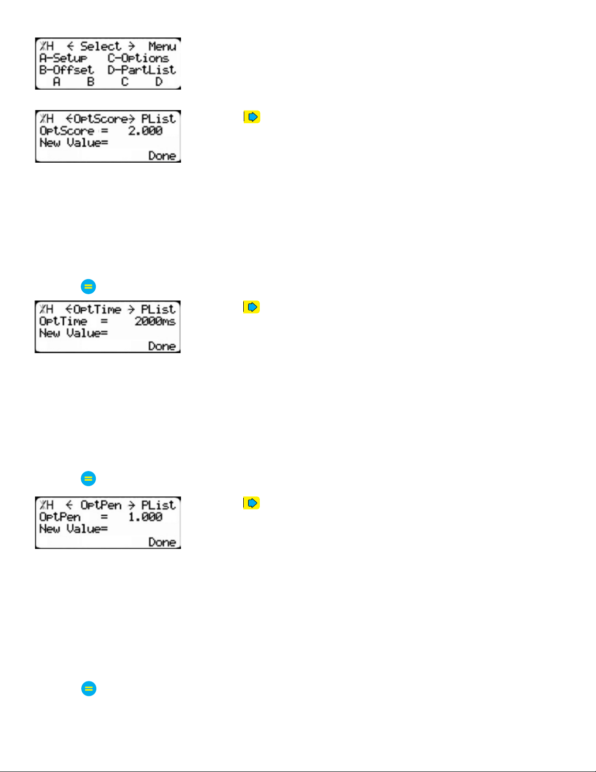
4. At the Menu Select screen, press the [PartList] soft key to access the
Part List menu.
5. Press to scroll through the settings until you get to the Opt Score
setting.
The Optimizer Score setting sets the score that the optimizer solution must reach to be considered a
good solution.
A lower Opt Score setting will give you a better optimized solution, but will take longer to do so.
A higher Opt Score setting will give you a faster solution, but it may give you a lower material yield.
To change Opt Score...
1. Enter the new Opt Score setting.
2. Press to save the parameter.
6. Press to scroll through the settings until you get to the Opt Time
setting.
The Optimizer Time setting sets the amount of time the TigerStop Optimizer has to find a solution. If it
takes longer than this time, TigerStop will use the best found optimized solution.
A lower Opt Time setting will give you a faster solution, but it may give you a lower material yield.
A higher Opt Time setting will give you better material yield, but it may take longer to do so.
To change Opt Time...
1. Enter the new Opt Time setting.
2. Press to save the parameter.
7. Press to scroll through the settings until you get to the Opt Pen
setting.
The Optimizer Penalty setting sets a penalty for multiple board optimized solutions. This means that the
higher this setting, the more TigerFence will try to Rip wider parts first.
A lower Opt Pen setting will give you faster optimization with more short parts processed first.
A higher Opt Pen setting will give you a slower optimization with more long parts processed first.
To change Opt Pen...
1. Enter the new Opt Pen setting.
2. Press to save the parameter.
By adjusting these three optimizer settings, you can greatly influence how the TigerStop optimizer works
to suit your exact application.

20
Basic TigerFence Functions
Basic TigerFence Functions
Manual Movement
To manually move TigerFence to a position, you must enter the length you want TigerFence to go to.
This length can be entered as a decimal or a fractional value.
Entering Decimals
1. Start at the Ready Screen.
2. Enter a length at the controller.
Example: To enter 24 1/2 as a decimal, enter [2] [4] [.] [5].
3. Press [Start] to move TigerFence.
Entering Fractions
4. Start at the Ready Screen.
5. Enter a length at the controller.
Example: To enter 24 1/2 as a decimal, enter [2] [4] [1] [/] [2].
6. Then press
START
to move TigerFence.
Notice that even though you entered a fraction, TigerFence will display
the position as a decimal once it has moved. TigerFence cannot display
fractions in the ‘Position’ field.
Calculator Mode
1. Start at the Ready Screen.
TigerFence has a calculator function that can be used to do simple math problems.
Table of contents
Popular Lathe manuals by other brands

Grizzly
Grizzly G8690 instruction manual

Hunter
Hunter BL Series Operation instructions

Grizzly
Grizzly G4003 owner's manual

Trak Machine Tools
Trak Machine Tools DPMRX5 Site preparation guide

Huvema
Huvema HU 360 VAC X 1000 Operation manual

Proxxon
Proxxon PD 400 Translation of the original operating instructions

Lortone
Lortone NS8 Instructions and parts list

Smithy
Smithy MI-329M Operator's manual

Clarke
Clarke WOODWORKER CWL325V Operation & maintenance instructions

CHESTER
CHESTER Voyager Lathe Operation manual

Roper Whitney
Roper Whitney U412 Operation, parts & maintenance manual

KAKA Industrial
KAKA Industrial 3-IN-1/5216 Operation manual


