CHESTER Voyager Lathe User manual


Warning!
1. Read and understand the entire instruction manual before attempting to
assemble or operate the machine.
2. This lathe has been designed and is intended to be used by trained and
experienced personnel only. If you are not familiar with the correct and safe
operation of a lathe, do not operate this machine until you have been properly
trained.
3. Always wear approved safety glasses/face shields when using this machine.
4. Ma e certain the machine has been properly grounded.
5. Before operating the machine, remove ties, rings watches and other jewellery,
rollup sleeves above the elbows, remove loose clothing and confine long hair.
Do not wear gloves.
6. Keep the floor around the machine clean and free from scrap material, oil and
grease.
7. Keep the machine guards in place at all times when the machine is in use, if
they are removed for maintenance purposes, use extreme caution and replace
the guards immediately.
8. Do not over reach, maintain a balanced stance at all times so that you do not
fall or lean against cutting tools or the moving parts.
9. Ma e all machine adjustments or maintenance when the machine has been
unplugged from the power supply.
10. Do not force a tool or attachment to do a job which it was not designed for.
11. Replace any warning labels if they become damaged or obscured.
12. Ma e sure that the power switch is in the off position before connecting the
machine to the power supply.
13. Give your wor your undivided attention at all times, loo ing around,
continuing a conversation and general “horse-play” are careless acts that can
result in serious injury.
14. Keep visitors a safe distance from the wor area.
15. Use recommended accessories, using unsuitable accessories can be
hazardous.
16. Ma e a habit of chec ing to see that eys and adjusting wrenches are
removed before turning the machine on.
17. Never attempt any operation or adjustment if the procedure is not understood.
18. Keep fingers away from any rotating parts and cutting tools while in operation.
19. Keep the belt guard in place and in wor ing order.
20. Never force the cutting action.
21. Do not attempt to adjust or remove tools during operation.
22. Always use identical replacement parts when servicing the machine.
23. Always use eep cutting tools sharp.
24. Never operate or allow the machine to be operated by personnel under the
influence of alcohol or drugs.
25. Failure to comply with the above warnings may cause serious injury.
2

Contents
Warnings!
1. Specifications
2. Uncrating and Cleaning
3. Chuck Preparation
4. Lubrication
. Coolant Preparation
6. Electrical Connections
7. General Description
8. Controls
9. Break-In Procedure
10. Operation
11. Adjustments
12. Removable Gap
13. V-Belts
14. Aligning the Tailstock to Headstock
1 . Foundation Plans
16. Parts List and Drawings
3

1. Specifications
Swing Through the Gap 508mm
Distance Between Centres 1000mm
Hole Through Spindle 40mm
Spindle Nose D1-4
Taper in Spindle Nose MT5
Spindle Taper Adaptor MT3
Number of Spindle Speeds 12
Range of Spindle Speeds 40-1800rpm
Number of Longitudinal and Cross Feeds 42
Range of Longitudinal Feeds (mm/rev) 0.043-0.653
Range of Cross Feeds (mm/rev) 0..024-0.359
Number of Inch Threads 28
Range of Inch Threads 4-56TPI
Number of Metric Threads 37
Range of Metric Threads 0.4-7mm
Toolpost Type 4-Way
Maximum Tool Size 16x16mm
Maximum Compound Slide Travel 88mm
Maximum Cross Slide Travel 170mm
Maximum Carriage Travel 950mm
Tailstoc Spindle Travel 120mm
Diameter of Tailstoc Spindle 45mm
Taper in Tailstoc Spindle MT3
Overall Dimensions
1900x710x1170m
m
Net Weight 1200Kg
Gross Weight 1300Kg
4

2. Uncrating and Cleaning
1. Remove the crate from around the lathe carefully.
2. Unbolt the lathe from the shipping crate base.
3. Choose a suitable location for the lathe that is dry, is well lit and that has
enough room around to be able to perform maintenance to the entire machine.
4. Place two steel rods or pipes (of sufficient strength) into the four holes (A, Fig
1) of the lathe stand. Place slings around the rods (ma e sure that they are of a
sufficient capacity). DO NOT lift by the spindle. Use a crane to list the machine
and slowly raise the lathe from the base, ma e sure that the lathe is balanced
before moving.
Fig 1
5. To avoid twisting the bed, the lathes location must be absolutely flat and level,
use an engineer’s precision level on the beds ways in both the longitudinal and
cross directions. Levelling pads have been included with the machine, use these
and the levelling screws to adjust the level of the machine. The lathe must be
level to be accurate.
6. Clean the anti-rust oil from the surfaces of the machine with a mild
commercial solvent or erosene. Do not use paint thinner, gasoline or lacquer
thinner as these will damage the painted surfaces. Once the surfaces have been
cleaned apply a thin layer of machine oil to protect the bare metal surfaces from
rust.
7. Open the end gear door, clean all of the components and the coat the gears
with heavy oil or non-slinging grease, close the door before use.
5

3. Chuck Preparation
Note: Before removing the chuc form the spindle, place a wooden bloc across the
guideways under the chuc .
1. Support the chuc while turning the three camloc s ¼ turn counter-cloc wise
with the chuc ey.
2. Carefully remove the chuc from the spindle and place it onto an adequate
wor surface.
3. Inspect the camloc studs and ma e sure that they have not become crac ed
or bro en during transport. Clean all of the parts thoroughly and clean the
spindle and camloc s to ensure that the chuc mates with the spindle securely.
4. Cover the chuc jaws and scroll inside the chuc with a thin layer of oil, cover
the spindle, cam loc s and the chuc body with a light film of heavier oil.
5. Lift the chuc up to the spindle nose and press onto the spindle. Tighten the
chuc in place by turning the camloc s ¼ turn cloc wise, the index mar (A, Fig
2) on the camloc should be between the two indicator arrows (B, Fig 2). If the
index mar is not between the two arrows, remove the chuc and adjust the
camloc studs by either turning out one full turn (if the cam will not engage) or
turning in one full turn (if the cams turn beyond the indicator mar s).
6
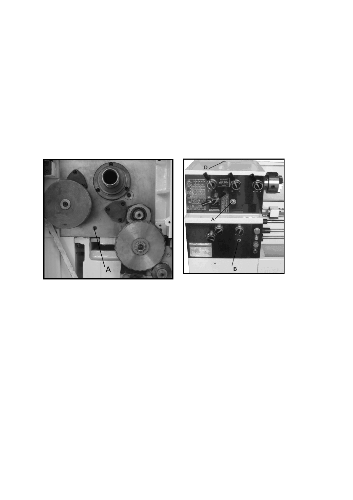
Lubrication
Caution! The lathe must be kept well lubricated at all times and all reservoirs
filled to their operating levels before starting the machine. Failure to comply
may cause serious damage to the lathe!
1. Headstoc : The oil must be filled to the indicator mar on the oil sight glass
(A, Fig 3). The oil can be poured into the headstoc once the plug (D, Fig 3) has
been removed. To drain the oil from the headstoc , unscrew the drain plug (A,
Fig 4) with an 8mm Allen ey, drain the oil completely and tighten the drain plug
bac into place. Drain and replace the oil in the headstoc after first month of
operation, then every 12 months.
Fig. 3
2. Gearbox: The oil must be filled to the indicator mar on the oil sight glass (A,
Fig 3). The oil can be poured into the gearbox once the plug (C, Fig 5) has been
removed. To drain the oil from the gearbox, unscrew the drain plug (A, Fig 5)
with an 8mm Allen ey, drain the oil completely and tighten the drain plug bac
into place. Drain and replace the oil in the gearbox after first month of operation,
then every 12 months.
7

Fig. 5
3. Apron: The oil must be filled to the indicator mar on the oil sight glass (A, Fig
6). The oil can be poured into the apron once the plug (B, Fig 6) has been
removed. To drain the oil from the apron, unscrew the drain plug with an 8mm
Allen ey, drain the oil completely and tighten the drain plug bac into place.
Drain and replace the oil in the apron after first month of operation, then every 12
months.
Fig 6
4. Leadscrew/Feed Rod: Lubricate the
ball oiler (A, Fig 7) on the
leadscrew/feed rod brac et once daily.
5. Tailstoc : Lubricate the two ball
oilers (B, Fig 7) once daily.
Fig. 7
6. Cross Slide: Lubricate the four ball oilers (A, Fig 8) once daily
8

7. Compound Rest: Lubricate one ball
oiler (B, Fig 8) once daily
8. Carriage: Lubricate the four ball
oilers (D, Fig 8) once daily
Fig. 8
9

Coolant Preparation
Caution! Follow the manufactures recommendations for use, care and
disposal.
Remove the rear access cover on the tailstoc end and ma e sure that the coolant
tan has not shifted during transport and is properly located under the recovery
chute.
Fig 9.
Pour three gallons of coolant mix into the chip pan and, once the power has been
connected, turn on the coolant pump and chec to see that the coolant is cycling
properly. Once this has all been chec ed, secure the coolant door bac onto the
stand.
Electrical Connections
Warning! All electrical connections must be completed by a qualified
electrician! Failure to comply may cause serious injury and/or damage to the
machinery and property!
Lathe Power Source Junction Box: Remove the cover. Run the main power through
the strain relief bushing and attach the ground, followed by the power leads.
Replace the cover.
Main Power Switch: Located on the rear of the machine. Turns the power to the
machine on and off.
Ma e sure that the lathe is properly grounded.
To ensure that the lathe has been connected correctly, pull up the forward/reverse
lever, the spindle should rotate in a counter-cloc wise direction when viewed from
the tailstoc . If the spindle rotates cloc wise, turn the power off and change any two
10

of the phases into the machine before re-connecting the power and restarting the
machine.
Warning! Disconnect the machine from the power source, failure to do so may
cause serious injury!
Main Motor: Change the wires according to the diagram on the inside of the motor
junction box.
Coolant Pump: Open the access panel on the base at the tailstoc end and change
the wires in the coolant pump junction box as per the diagram on the inside of the
junction box.
General Description
Lathe Bed
The lathe bed (A, Fig 10) is made of high
grade cast iron, by combining high chee s
with strong cross ribs, a bed with low
vibration and high rigidity is realized. Two
precision ground vee slideways, reinforced
by heat hardening and grinding are an
accurate guide for the carriage and
headstoc . The main drive motor is
mounted in the stand below the
headstoc .
Fig 10.
Headstock
The headstoc (B, Fig 10) is cast from high grade, low vibration cast iron. It is bolted
to the bed by four screws with two adjusting screws for alignment. In the head, the
spindle is mounted on two precision taper roller bearings. The hollow spindle has
Morse Taper #5 with a 1½” bore.
11
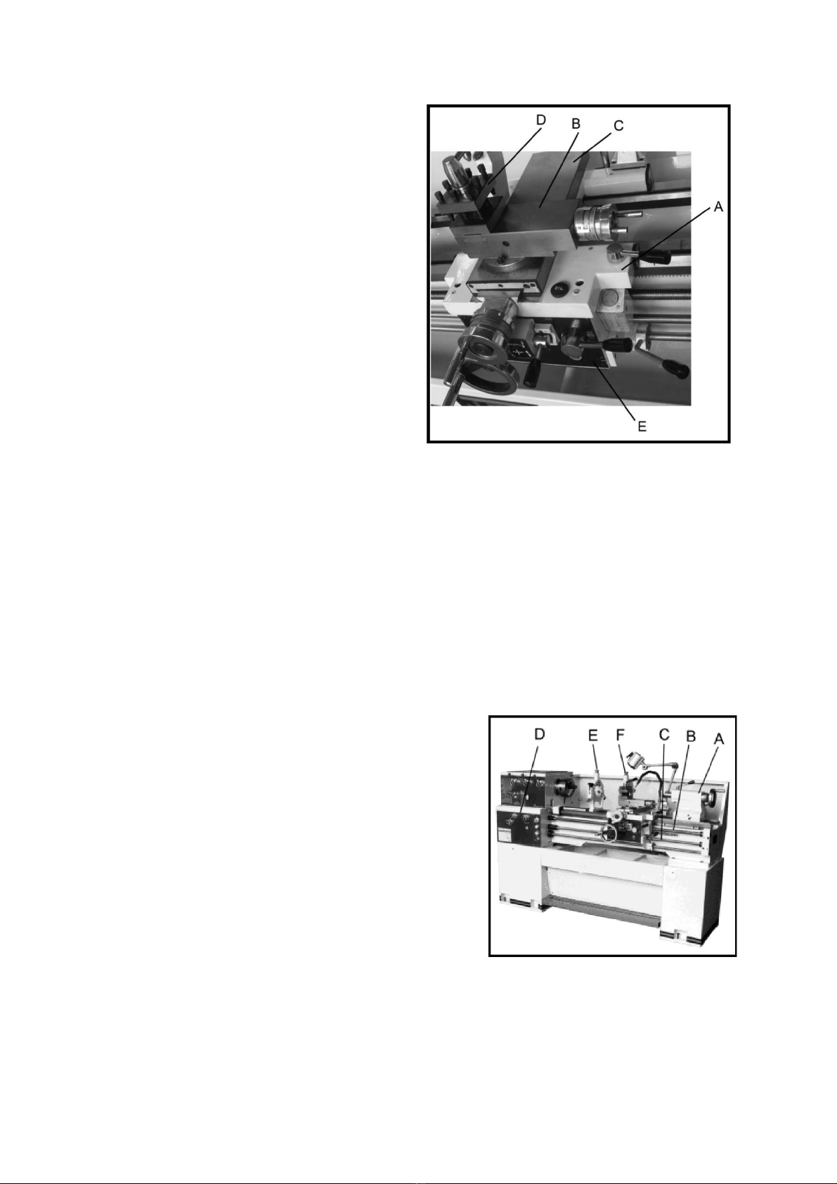
Carriage
The carriage (A, Fig 11) is made from
high quality cast iron, the sliding parts
are ground smooth. The cross-slide is
mounted on the carriage and moves on a
dove tailed slide which can be adjusted
for play by adjusting the gibs.
The compound slide (B, Fig 11) is
mounted on the cross slide (C, Fig 11)
and can be rotated through 360°. The
top slide and the cross-slide travel in a
dovetail slide and have adjustable gibs.
The four-way tool post is fitted on the top
slide.
Fig 11.
Four-Way Tool Post
The four-way tool post (D, Fig 11) is mounted on the top slide and allows a maximum
of four tools to be mounted simultaneously. Remember to use a minimum of two
clamping screws when installing the cutting tool.
Apron
The apron (E, Fig 11) is mounted to the carriage. The apron has a half nut fitted, the
half nut gibs can be adjusted from the outside and can be engaged by the use of a
lever. The quic travel of the apron is accomplished by means to a bed mounted
rac and pinion and operated by a handwheel on the front of the apron.
Tailstock
The Tailstoc (A, Fig 12) slides on a V-way and
can be loc ed at any location by a clamping
lever. The tailstoc has a heavy duty spindle with
a Morse taper #3.
Leadscrew and Feed Rod
The leadscrew (B, Fig 12.) and feed rod (C, Fig
12) are mounted on the front of the machine bed.
They are connected to the gearbox at the left for
automatic feed and lead and are supported by
bushings on both ends, they are equipped with
brass shear pins.
Gearbox
12

The gearbox (D, Fig 12) is made from high quality cast iron and is mounted to the left
side of the machine bed.
Steady Rest
The steady rest (E, Fig 12) serves as a support for shafts on the free tailstoc end.
The steady rest is mounted on the bed way and secured below with bolt, nut and
loc ing plate. The sliding fingers require continuous lubrication at the contact points
with the wor piece to prevent premature wear.
To set the steady rest:
1. Loosen the three hex
screws
2. Loosen the nurled
screw and open the sliding fingers until the steady rest can be moved with its
fingers around the wor piece. Secure the steady rest into position.
3. Set the fingers snugly
to the wor piece and secure the three hex soc et screws. The fingers should be
snug but not overly tight. Lubricate the sliding points with heavy oil.
4. After prolonged use,
the fingers will show wear, re-mill or file the tips of the fingers.
Follow Rest
The travelling follow rest (F, Fig 12) is mounted on the saddle and follows the
movement of the turning tool. Only two fingers are required as the place of the third
is ta en by the turning tool. The follow rest is used for turning long and slender
wor piece, it prevents the wor piece from flexing due to the pressure created by the
cutting tool.
The sliding fingers are set in a similar fashion to the steady rest, snug but not overly
tight. Always use a heavy oil to lubricate the contact point.
Controls
1.
Control Panel – located on the front of the
gearbox
A. Coolant On/Off Switch (A, Fig 13), turns
the coolant on and off.
B. Power Indicator Light (B, Fig 13), will
illuminate when the lathe has power.
C. Emergency Stop Button (C, Fig 13), press
to stop all of the machine functions.
Caution – lathe will still have power, twist
the button to re-set.
13

D. Jog Switch (D, Fig 13), press and release immediately to advance the spindle
position.
2. Headstoc Gear
Change Levers (E, Fig 13) – located on the front of the headstoc , move the
levers according to the speed chart for the desired speed setting.
3. Leadscrew/Feed Rod
Direction Lever (F, Fig 13) – Located on the front of the headstoc , Moving the
lever up will allow the carriage tot travel in the direction of the tailstoc ; moving
the lever down will allow the carriage to move in the direction of the headstoc
when the spindle is rotating in either direction.
Do not move the lever whilst the machine is running.
4. Feed/Leadscrew
Selector Lever (G, Fig 13) – located on the front of the headstoc , used when
setting up for threading or feeding.
Caution: in the “A” position, never run the lathe at speeds higher than 650rpm.
5. Feed/Leadscrew
Selector Lever (H, Fig 13) – located on the front of the gearbox and is used when
setting up for feeding and threading. Positions “F” and “D” are for the feed rod.
Position “E” and “C” are for the feed screw. Position “0” is neutral.
6. Loc Knob (I, Fig 13) –
Located on the front of the gearbox. When the nob is in the six o’cloc position,
the feed/leadscrew selector lever (J, Fig 13) can be adjusted. With the nob in
the 12 o’cloc position, the same lever will be loc ed.
7. Feed/Leadscrew
Selector Knob (J, Fig 13) – located on the front of the gearbox, it is used when
setting up for feeding and threading.
8.
Compound Loc (A, Fig 14) – This is a Hex
Soc et Screw located on the left side of the
compound slide. Turn cloc wise to loc and
counter-cloc wise to unloc .
9.
Carriage Loc (B, Fig 14) – The loc handle is
located on the top of the carriage, turn it
cloc wise to loc the carriage and counter-
cloc wise to unloc the carriage.
Caution: The carriage must be unloc ed
before engaging automatic feeds to prevent causing damage to the lathe.
10. Longitudinal Traverse
Handwheel (D, Fig 14) – located on the apron assembly, rotate the handwheel
cloc wise to move the apron assembly towards the tailstoc , rotate counter-
cloc wise to move the apron assembly towards the headstoc .
14

11. Feed Selector (E, Fig
14) – located in the centre front of the apron, pushing the lever to the left and
dfown activates the cross feed function, pulling the lefer to the right and up
activates the longitudinal function.
12. Half-Nut Engagement
Lever (Thread Cutting) (F, Fig 14) – located on the frnt of the apron, move the
lever down to engage the half-nut and move bac up to disengage.
13. Cross Traverse
Handwheel (G, Fig 14) – located above the apron, rotate cloc wise or counter-
cloc wise to move the cross slide into position.
14. Compound Rest
Traverse Handwheel (H, Fig 14) – located on the end of the compound slide,
rotate the handwheel cloc wise or counter-cloc wise to move the compound slide
inot position.
15. Tool Post Clamping
Lever (J, Fig 14) – located on the top of the tool post, rotate counter-cloc wise to
loosen and cloc wise to tighten.
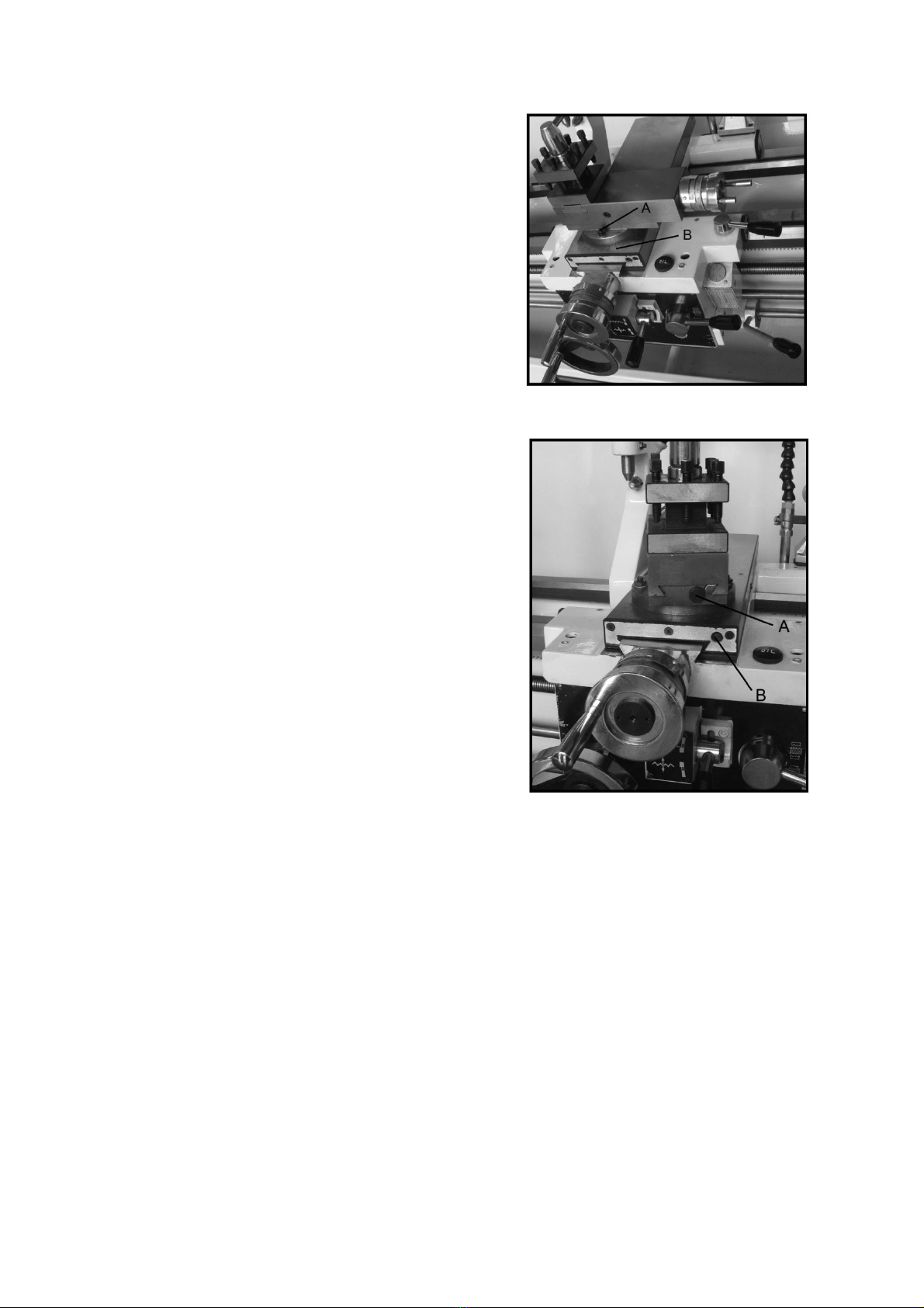
16.
Tailstoc Quill Clamping Lever (A, Fig 15) –
located on the tailstoc , rotate cloc wise to loc
the quill and counter-cloc wise to unloc .
17.
Tailstoc Clamping Lever (B, Fig 15) – located on
the tailstoc , lift the lever to loc the tailstoc into
position and push bac dow to release the
tailstoc .
18. Tailstoc Quill Traverse
Handwheel (C, Fig 15) – located on the tailstoc , rotate the handwheel cloc wise
to move the quill forward and counter-cloc wise to retract the quill.
19. Tailstoc Off-Set
Adjustment (D, Fig 15) – Two hes soc et cap screws located on the tailstoc
base are used to off-set the tailstoc for cutting tapers, loosening the one screw
whilst tightening the other will set the tailstoc into position.
20.
Foot Bra e (A, Fig 16) – located between the
stand pedestals, push the lever down to stop
the machine.
21.
Micro Carriage Stop (B, Fig 16) – located on
the bed, loosen the two hex soc et cap
screws underneath the body and slide along
the bed to the desired position. Re-tighten the
screws to hold in place.
15

22. Main Power Switch (not
shown) – located on the electrical box door on the rear of the lathe. Turns the
main power to the lathe on and off.
Break-In Procedure
During manufacture and testing, this lathe has been run in the low rpm range for
three hours.
To allow time for the gears and bearings to brea in and run smoothly, do not run the
lathe above 650rpm during the first six hours of operation and use.
Operation
Feed and Thread Selection
1.
Use the feed and thread chart found on
the gearbox faceplate table (A, Fig 17 and
thread tables in this manual).
2.
Move the levers (B, C, D, E and F, Fig 17)
to the required positions according to the
chart.
Change Gear Replacement
The 30T, 12T and 60T gears are installed in
the end gear compartment when delivered
from the factory. This combination will cover most inchfeeds and threads under
normal circumstances.
The 24T, 32T, 40T, 65T, 66T and 70T gears found in the toolbox are used with
different combinations as indicated on the feed and thread tables.
1. Disconnect the
machine from the power source.
2. Remove the end cover
on the left-hand side of the headstoc .
3. Loosen the nuts (A and
B, Fig 18)
4. Move the quadrant (C,
Fig 18) out of the way and hold in place temporarily by tightening the nut (A and
B).
16

5.
Remove the hex soc et cap screws (D
and/or E, Fig18) depending on the which
gear is being changed.
6.
Install the new gear(s) and tighten into
place with a hex soc et cap screw.
7.
Loosen the nut (B, Fig 18) and move the
quadrant bac so that the teeth mesh on
the gears and tighten the nuts (A and B).
Caution:Ma e sure that the is a bac lash of
0.002” -0.003” between the gears, setting
the gears too tight will cause excessive noise and wear.
8. Close the door and
connect the machine to the power source.
Automatic Feed Operation and Feed Changes
1.
Move the forward/reverse selector (A, Fig
19) up or down depending on the required
direction.
2.
Set the selectors (A, B, C and D, Fig 20) to
the desired rate.
Note:for feeding, lever D will be set at “F” or
“D” depending on the desired feed rate.
Powered Carriage Travel
1. Push the lever (D, Fig
19) to the left and down to engage the cross feed.
2. Pull the lever to the
right and up to engage the longitudinal feed.
17

Thread Cutting
1.
Set the forward/reverse lever (A, Fig 19) up or
down depending on the desired direction.
2.
Set the selectors (A, B, C and D, Fig 20) to the
desired rate.
Note:for feeding, lever D will be set at “C” or “E”
depending on the desired thread.
3.
Push the lever (B, Fig 19) to the right.
4.
Engage the Half-Nut lever (C, Fig 19).
5. To cut inch threads,
use the feed and thread tables, the half nut lever and the threading dial are used
to thread in the conventional manner. The thread dial chart specifies at which
pointa thread can be entered using the threading dial.
6. To cut metric threads,
the half nuts must be left continually engaged once the start point has been
selected and the half nut is initially enaged (the thread dial cannot be used.
Metric Thread Table
18

Inch Lead and Feed Table
Compound Rest
19
The compound rest is located on top of the
cross slide and can be rotated around 360°.
Loosen the two soc et head cap screws (A, Fig
21) on the compound rest base. Use the
calibrated dial (B, Fig 21) below the rest to
assist the placement of the compound rest to
the desired angle.
Adjustments
After a period of time, wear in some of the
moving components may need to be adjusted:
Saddle
1.
Locate the four hex nuts found on the bottom
rear of the cross slide and bac the off one
full turn each.
2.
Turn each of the four set screws with a hex
wrench until a slight resistance is felt. Do not
overtighten these screws.
3.
Move the carriage with the handwheel and
determine if the drag is correct, readjust the
set screws as necessary to achieve the
desired drag.
4.
Hold the soce t set screw firmly with a hex
wrench and tighten the hex nut to loc the set screw in place.
5. Move the carriage
again and readjust if necessary.
Note: Over adjustment will cause excessive and premature wear of the gibs.
Cross Slide
If the cross slide is too loose, use the following procedure to tighten.
1. Loosen the rear gib
strip (not shown) approximately one turn.
2. Tighten the front gib
strip (B, Fig 22) a quarter turn. Turn the cross slide handwheel to see if the cross
slide is loose. If it is still loose, tighten the front screw a bit more and try again.
3. When the cross slide is
properly adjusted, tighten the rear gib strip.
Note: Over adjustment will cause excessive and premature wear of the gibs.
20
Table of contents
Other CHESTER Lathe manuals

CHESTER
CHESTER Coventry Pro User manual

CHESTER
CHESTER Crusader User manual

CHESTER
CHESTER CONQUEST SUPER LATHE User manual

CHESTER
CHESTER Crusader Deluxe Lathe User manual

CHESTER
CHESTER DB10VS User manual

CHESTER
CHESTER DB11VS User manual

CHESTER
CHESTER Centurion Series User manual

CHESTER
CHESTER Cobra Mill User manual

CHESTER
CHESTER CONQUEST SUPER User manual

CHESTER
CHESTER DB8VS User manual


