TIGIEFFE AIRO R Series User manual

PIATTAFORME AEREE SEMOVENTI
SELF-PROPELLED WORK-PLATFORMS
PLATES-FORMES DE TRAVAIL AUTOMOTRICES
SELBSTFAHRENDE HUBARBEITSBÜHNEN
PLATAFORMAS ELEVADORAS AUTOPROPULSADAS
ZELFRIJDENDE HOOGWERKERS
SJÄLVGÅENDE ARBETSPLATTFORMAR
SAMOKRETNE RADNE PLATFORME
“R” SERIES
R13 S R13 DC R17 S R17 DC
USE AND MAINTENANCE MANUAL
- ENGLISH - ORIGINAL INSTRUCTIONS
AIRO is a division of TIGIEFFE SRL
Via Villasuperiore, 82 - 42045 Luzzara (RE) ITALY-
+39-0522-977365 -+39-0522-977015
WEB: www.airo.com
059.20.UEM-ENG
2018-05

Use and Maintenance Manual - R13 R17 Series
Page 2
Revision date
Description of revision
2010-01
Update due to new machine directive 2006/42/EC.
Model names updated.
2010-11
Added instructions for biodegradable oil kit.
Temperatures and oil list updated.
2011-02
Updated description for load control
2011-05
Amended information on “Commissioning and first inspection, subsequent inspections and
title transfer report”.
Inserted “Total quantity of battery electrolyte” in Technical Data.
Corrected "Max. power" diesel motor and inserted "Adjusted Power".
2013-01
Changed maximum drive speed due to displacement pump change
2013-10
Specified instructions for harness anchoring points.
2014-03
Specified instructions for drive on uneven surfaces and/or slopes.
2014-08
Inserted instructions for optional kit "extendible tracks".
Inserted information on maximum limits of manual forces.
2015-00
CE conformity declaration updated.
Added position of hands instruction.
2015-10
Type of usable hydraulic oil updated.
Added indication for spare parts. They must be original or approved by the manufacturer of
the machine.
Added "Leaving at height”.
2018-05
Data sheets were added with units of measurement of the international system and US unit
of measurement.
Changed Name and Surname of CEO.
Unified First and Second Part.

Use and Maintenance Manual - R13 R17 Series
Page 3
Tigieffe thanks you for purchasing a product of its range, and invites you to read this manual. Here you can find all the necessary
information for a correct use of the purchased machine; therefore, you are advised to follow the instructions carefully and to read
the manual thoroughly. The manual should be kept in a suitable place where no damage can occur to it. The content of this manual
may be modified without prior notice and further obligations in order to add changes and improvements to the units already
delivered. No reproduction or translation may take place without the written permission of the owner.
Contents:
1. INTRODUCTION..........................................................................................................................................6
1.1. Legal aspects..............................................................................................................................................6
1.1.1. Delivery of the machine ................................................................................................................................................6
1.1.2. Declaration of commissioning, first check, further periodical checks and transfers of ownership.................................6
1.1.2.1. Declaration of commissioning and first check ............................................................................................................ 6
1.1.2.2. Further periodical checks ........................................................................................................................................... 7
1.1.2.3. Transfers of ownership............................................................................................................................................... 7
1.1.3. Operator training and information .................................................................................................................................7
1.2. Tests performed before delivery...............................................................................................................7
1.3. Intended use ...............................................................................................................................................7
1.3.1. Leaving at height...........................................................................................................................................................8
1.4. Description of the machine........................................................................................................................8
1.5. Control panels ............................................................................................................................................9
1.6. Drive power.................................................................................................................................................9
1.7. Machine life, demolition and decommissioning ......................................................................................9
1.8. Identification .............................................................................................................................................10
1.9. Location of main components.................................................................................................................11
2. TECHNICAL FEATURES OF STANDARD MACHINES............................................................................12
2.1. Model R13 S ..............................................................................................................................................12
2.2. Model R13 DC ...........................................................................................................................................14
2.3. Model R17 S ..............................................................................................................................................17
2.4. Model R17 DC ...........................................................................................................................................19
2.5. Vibrations and noise ................................................................................................................................22
3. SAFETY PRECAUTIONS ..........................................................................................................................23
3.1. Personal protective equipment (PPE).....................................................................................................23
3.2. General safety norms...............................................................................................................................23
3.3. Use instructions .......................................................................................................................................24
3.3.1. General.......................................................................................................................................................................24
3.3.2. Handling......................................................................................................................................................................24
3.3.3. Operating procedures .................................................................................................................................................25
3.3.4. Wind speed according to Beaufort scale.....................................................................................................................26
3.3.5. Pressure of the machine on ground and load-bearing capacity of ground..................................................................27
3.3.6. High-tension lines .......................................................................................................................................................28
3.4. Dangerous situations and/or accidents..................................................................................................28
4. INSTALLATION AND PRELIMINARY CHECKS.......................................................................................29
4.1. Becoming acquainted with the machine ................................................................................................29
4.2. Preliminary operation checks..................................................................................................................29
5. USE INSTRUCTIONS ................................................................................................................................30
5.1. Platform control panel/wire control ........................................................................................................30
5.1.1. “Wire control” Mode: Translation, Stabilization and Widening tracks (optional)..........................................................32
5.1.1.1. Drive......................................................................................................................................................................... 33
5.1.1.2. Stabilization.............................................................................................................................................................. 34
5.1.1.2.1. Manual stabilization control...................................................................................................................................... 35
5.1.1.2.2. Automatic stabilization control (OPTIONAL) ............................................................................................................ 35
5.1.1.3. Widening or narrowing the tracks (optional)............................................................................................................. 36
5.1.2. Mode “Platform movement”: Lifting/Lowering/Rotations .............................................................................................38

Use and Maintenance Manual - R13 R17 Series
Page 4
5.1.2.1. First boom lifting/lowering......................................................................................................................................... 39
5.1.2.2. Second boom lifting/lowering.................................................................................................................................... 39
5.1.2.3. Telescopic boom extension/retraction...................................................................................................................... 39
5.1.2.4. Jib lifting/lowering..................................................................................................................................................... 39
5.1.2.5. Turret orientation (rotation)....................................................................................................................................... 39
5.1.2.6. Platform rotation (OPTIONAL).................................................................................................................................. 40
5.1.2.7. Platform level compensation .................................................................................................................................... 40
5.1.3. Other functions of the platform control panel ..............................................................................................................41
5.1.3.1. Electric / thermic power selector (F) (OPTIONAL) ................................................................................................... 41
5.1.3.2. Electric motor start / stop button (E) (OPTIONAL) ................................................................................................... 41
5.1.3.3. Enabled electric pump warning light (T) (OPTIONAL).............................................................................................. 41
5.1.3.4. Heat motor starting switch (G).................................................................................................................................. 41
5.1.3.5. Horn (B).................................................................................................................................................................... 41
5.1.3.6. Emergency STOP button (P).................................................................................................................................... 41
5.1.3.7. Warning lights........................................................................................................................................................... 42
5.1.3.7.1. Enabled control panel warning light (ZB).................................................................................................................. 42
5.1.3.7.2. Central turret warning light (ZC) ............................................................................................................................... 42
5.1.3.7.3. Enabled warning light Diesel motor fault / low fuel level (ZD) (DIESEL motor only)................................................. 43
5.1.3.7.4. Danger warning light (unsteady position and faults indicator)(ZE) ........................................................................... 43
5.1.3.7.5. Overload alarm warning light (ZF)............................................................................................................................ 43
5.1.3.7.6. Outriggers position warning lights (ZA) .................................................................................................................... 43
5.2. Ground control panel (electric control unit)...........................................................................................44
5.2.1. On-off key / control panel selector (A).........................................................................................................................45
5.2.2. Emergency stop button (B) .........................................................................................................................................45
5.2.3. Thermic or electric work power selector (C) (OPTIONAL)..........................................................................................45
5.2.4. Heat motor start button (D) .........................................................................................................................................46
5.2.5. User interface display (E)............................................................................................................................................46
5.2.6. Machine warning light on (G)......................................................................................................................................46
5.2.7. Heat motor warning lights (H,L,M and N) (DIESEL motor only)..................................................................................46
5.2.8. Platform control levers (O,P,Q,R,S,T,U) .....................................................................................................................46
5.3. Platform access........................................................................................................................................47
5.4. Machine start-up.......................................................................................................................................48
5.4.1. Heat motor start-up.....................................................................................................................................................49
5.4.2. Starting the 230V electric pump (OPTIONAL) ............................................................................................................49
5.5. Machine stop.............................................................................................................................................51
5.5.1. Normal stop.................................................................................................................................................................51
5.5.2. Emergency stop button..............................................................................................................................................51
5.5.3. Heat motor stop ..........................................................................................................................................................51
5.5.4. Stopping the 230V single-phase electric pump (OPTIONAL). ....................................................................................52
5.6. Emergency manual controls....................................................................................................................53
5.7. Socket (OPTIONAL) for electric tool connection and single-phase electric pump powering
(OPTIONAL) 55
5.8. Fuel level and re-fuelling..........................................................................................................................55
5.9. End of work...............................................................................................................................................56
6. HANDLING AND CARRYING....................................................................................................................57
6.1. Handling....................................................................................................................................................57
6.2. Carrying.....................................................................................................................................................57
7. MAINTENANCE.........................................................................................................................................60
7.1. Machine cleaning......................................................................................................................................60
7.2. General maintenance ...............................................................................................................................61
7.2.1. Various adjustments ...................................................................................................................................................62
7.2.2. Greasing .....................................................................................................................................................................63
7.2.3. Hydraulic circuit oil level check and change................................................................................................................64
7.2.3.1 Biodegradable hydraulic oil (Optional)...................................................................................................................... 65
7.2.3.2 Emptying .................................................................................................................................................................. 65
7.2.3.3 Filters........................................................................................................................................................................ 65

Use and Maintenance Manual - R13 R17 Series
Page 5
7.2.3.4 Washing ................................................................................................................................................................... 65
7.2.3.5 Filling........................................................................................................................................................................ 65
7.2.3.6 Commissioning / check ............................................................................................................................................ 65
7.2.3.7 Mix............................................................................................................................................................................ 66
7.2.3.8 Micro-filtration........................................................................................................................................................... 66
7.2.3.9 Disposal.................................................................................................................................................................... 66
7.2.3.10 Topping up ............................................................................................................................................................... 66
7.2.4. Hydraulic filter replacement ........................................................................................................................................67
7.2.4.1. Suction filters............................................................................................................................................................ 67
7.2.4.2. Return filter............................................................................................................................................................... 67
7.2.5. Drive reduction gear oil level check and change.........................................................................................................68
7.2.5.1 Checks in the use of synthetic biodegradable oil in drive reduction gears ............................................................... 68
7.2.6. Telescopic boom sliding blocks clearance adjustment ...............................................................................................69
7.2.7. Tracks condition and tension check............................................................................................................................70
7.2.8. Pressure relief valve adjustment and operation check................................................................................................71
7.2.9. Inclinometer operation check......................................................................................................................................72
7.2.10. Operation check of M1 microswitches ........................................................................................................................73
7.2.11. MRT microswitch operation check..............................................................................................................................73
7.2.12. M2A-M2B microswitches operation check. .................................................................................................................73
7.2.13. STP1-STP2-STP3-STP4 microswitches operation check...........................................................................................73
7.2.14. “Dead-man” safety system operation check................................................................................................................74
7.2.14.1. "Dead-man" pedal”................................................................................................................................................... 74
7.2.14.2. "Dead-man" button................................................................................................................................................... 74
7.3. Starter battery...........................................................................................................................................76
7.3.1. Starter battery maintenance........................................................................................................................................76
7.3.2. Starter battery recharge..............................................................................................................................................76
7.3.3. Battery block...............................................................................................................................................................77
7.3.4. Battery charger: fault report ........................................................................................................................................77
7.3.5. Battery replacement....................................................................................................................................................78
8. MARKS AND CERTIFICATIONS...............................................................................................................79
9. PLATES AND STICKERS..........................................................................................................................80
10. CHECK REGISTER ...................................................................................................................................82
11. HYDRAULIC DIAGRAM ............................................................................................................................97
12. WIRING DIAGRAM....................................................................................................................................99
13. DECLARATION OF CONFORMITY EC FACSIMILE. .............................................................................110

Use and Maintenance Manual - R13 R17 Series
Page 6
1. INTRODUCTION
This Use and Maintenance Manual provides general instructions concerning the complete range of machines indicated on the
cover. Therefore the description of their components, as well as control and safety systems, may include parts not present on Your
machine since supplied on request or not available. In order to keep pace with the technical development AIRO-Tigieffe s.r.l.
reserves the right to modify the product and/or the use and maintenance manual at any time without updating the units already
delivered.
1.1. Legal aspects
1.1.1. Delivery of the machine
Within EU (European Union) member countries the machine is delivered complete with:
Use and Maintenance manual in your language
CE mark applied on the machine
CE conformity declaration
Guarantee certificate
Only for Italy:
Declaration of commissioning to INAIL
List of local INAIL departments
Declaration of internal testing
It is to be noted that the Use and Maintenance Manual is an integral part of the machine and a copy of this, together with copies of
the documents certifying that the periodical checks have been carried out, must be kept on board in its suitable container. In the
event of a transfer of ownership the machine must always be provided with its use and maintenance manual.
1.1.2. Declaration of commissioning, first check, further periodical checks and transfers of ownership
The legal obligations of the owner of the machine vary according to the country of commissioning. It is therefore recommended to
inquiry about the procedures in force in your country from the boards responsible for industrial safety. This manual contains a final
section called "Check register" for a better filing of documents and recording of any modifications.
1.1.2.1. Declaration of commissioning and first check
In ITALY the owner of the Aerial Platform must notify the use of the machine to the local competent INAIL and submit it to
periodical compulsory checks. The first of such checks is performed by the INAIL within sixty days from a request being made. In
the event of such time passing without the inspection being made, the employer can call in the ASL (Local Health Unit) or qualified
public or private services. Subsequent checks are made by the already-mentioned parties within thirty days from a request being
made. In the event of such time passing without these checks being made, the employer can call in qualified public or private
services. The checks are on a payment basis and the employer (machine owner) will be charged for them. For these checks, the
territorial inspection boards (ASL/USL or ARPA) and INAIL can be supported by qualified public or private services. The qualified
private institutes acquire the qualification of responsibles of the public service and refer directly to the public structure that controls
this function.
To declare the commissioning of the machine in Italy, send the form that is supplied together with other documents upon machine
delivery, by registered letter with advice of receipt.
The INAIL will assign a serial number when the First Check is performed before completing the “technical identification sheet” on
which it indicates only the details obtained from the already-operating machine or obtainable from the instruction manual. Such
document shall form an integral part of the machine documentation.

Use and Maintenance Manual - R13 R17 Series
Page 7
1.1.2.2. Further periodical checks
Yearly checks are compulsory. In Italy it is necessary that the owner of the Aerial Platform must apply for a periodical check by
sending a registered letter to the local competent inspection board (ASL/USL or ARPA or other qualified public or private services)
at least twenty days before the expiry of the year from the last check.
NB: If a machine without a valid control document should be moved in an area outside the competence of the usual inspection
board, the owner of the machine must ask the inspection board, competent for the new territory where the machine is to be used,
for the annual check.
1.1.2.3. Transfers of ownership
In case of transfer of ownership (in Italy) the new owner of the Aerial Platform must notify the ownership of the machine to the local
competent inspection board (ASL/USL or other qualified public or private services) by enclosing a copy of:
Declaration of conformity issued by the manufacturer.
Declaration of commissioning carried out by the first owner.
1.1.3. Operator training and information
The employer must ensure that the workers appointed to use the equipment are adequately and specifically trained so they are
able to use the Mobile Elevating Work Platform in a proper and safe way and also avoid the risks caused by other people.
1.2. Tests performed before delivery
Before being placed on the market, each MEWP undergoes the following tests:
Braking test
Overload test
Operating test
1.3. Intended use
The machine described in this use and maintenance manual is a self-propelled elevating work platform intended for lifting persons
and materials (equipment and work materials) in order to carry out maintenance, installation, cleaning, painting, de-painting, sand-
blasting, welding operations, etc.
The max. capacity allowed (which varies according to the model –see paragraph “Technical features”) is divided as follows:
80 Kg for each person on board.
40 Kg for equipment.
The remaining load is represented by the material being worked.
In any case NEVER exceed the maximum capacity allowed as indicated in paragraph "Technical features”. Persons, tools and work
materials can be loaded on the platform only from the access position (platform lowered). It is absolutely forbidden to load persons,
tools and work materials on the platform when it is not in access position.
All loads must be positioned inside the basket; do not lift loads (even if complying with the maximum capacity allowed) hanging
from the platform or lifting structure.
Do not carry large-sized panels since they increase the resistance to wind force thus causing the machine to overturn.
The machine is not equipped with an overload controller as in the design phase we considered stability and overload criteria
increased as reported by the EN280 in paragraphs 5.4.1.5 and 5.4.1.6 .
The machine cannot be used in areas where road vehicles operate. Always surround the working area by means of suitable signs
when the machine is used in public areas.
Do not use the machine to tow trucks or other vehicles.

Use and Maintenance Manual - R13 R17 Series
Page 8
All types of machine use other than those for which it was designed must be approved in writing by the machine manufacturer
following a specific request on the part of the user.
Do not use the machine for purposes other than those for which it was designed, except after making a
request and having obtained written permission in this sense from the manufacturer
1.3.1. Leaving at height
The work elevating platforms are not designed by taking into account the risks of the “leaving at height” because the only access
position considered is when the platform is completely lowered. For this reason this activity is formally forbidden.
However, there are exceptional conditions in which the operator needs to access or leave the work platform not in the access
position. This activity is normally defined as “leaving at height”.
The risks connected to the “leaving at height” do not depend exclusively on the PLE (work elevating platform) characteristics; a
specific risk analysis carried out by the employer can authorize this specific use by taking into account:
The working environment characteristics;
The absolute prohibition to consider the work platform as an anchoring point for people working outdoors;
The use of the machine at xx% of its performances to avoid that additional forces created by a specific operation or
bending of the structure move away the access zone from the unloading zone. Provide for some tests in order to define
these limitations;
Provide for a specific evacuation procedure in case of emergency (for example: an operator always on the platform, one at
the ground control panel while a third operator leaves the lifted platform );
Provide for a specific training of the staff both as operator and transported staff;
Equip the unloading zone with all the devices that are necessary to avoid the risk of fall of the staff that accesses/leaves
the platform.
What said above is not a formal authorization of the manufacturer for the “leaving at height”, but it wants to supply information to
the employer - who is fully responsible for that - which can be useful for the planning of this exceptional activity.
1.4. Description of the machine
The machine described in this use and maintenance manual is a self-propelled aerial platform equipped with:
motorized chassis equipped with rubber tracks and outriggers;
hydraulically driven rotating turret;
articulated boom operated by hydraulic cylinders (the number of articulations and cylinders varies according to machine
model).
operator platform (the max. capacity varies according to the model - see chapter "Technical features”).
The chassis consists of sheeting, box-type structures and electrically welded structural forms of different thickness. It is motorised
to allow the machine to move (see "General use instructions"). The 2 tracks are controlled by independent motors and equipped
with hydraulic parking brake, positive logic type (when drive controls are released brakes are automatically activated). On the
chassis there are four outriggers operated by hydraulic double acting cylinders that are controlled by solenoid valves directly
flanged on the same. The outriggers are held in position by non-return valves directly piloted and flanged on the same.
Upon request, the machine can be equipped with a system of tracks widening to widen the track width and increase stability in the
event of use on rough terrain.
The turret rests on a turntable fixed to the chassis and can be oriented (rotated) by 320° non-continuous around the central axle of
the machine by means of irreversible endless screw.
The lifting system, with articulated boom, can be divided into three main structures:
The first one, consists of a "simple parallelogram" system (R13) or a "double parallelogram" (R17) and named
"pantograph".
The second, consists of a lifting boom with telescopic extension.
The third, consists of the terminal boom named “Jib”.
Such lifting structures are driven by 4 double-acting hydraulic cylinders:

Use and Maintenance Manual - R13 R17 Series
Page 9
One cylinder for the “pantograph” extension.
One cylinder for the boom extension.
One cylinder for the extension/retraction of the telescopic boom.
One cylinder for the “jib” extension.
The hydraulic cylinders which move the articulated structure are provided with over-center valves directly flanged on the same.
These devices allow the booms to remain in position even if one of the supply tubes accidentally breaks.
The platform, hinged to the end of the “jib”, can be rotated by 120° totally (60° on the right and 60° on the left) by means of an
electric actuator fitted with over-centre valve. It is fitted with guardrails and toe boards of prescribed height (the guardrails height
1100 mm; the toe boards height 150 mm). The platform levelling is automatic and is ensured by mechanical ties and two cylinders
in closed circuit. The manual level compensation is possible by acting on the relevant control only with completely lowered booms
(“Jib” inclination excluded).
1.5. Control panels
The machine is equipped with two control panels:
On the platform for normal use of the machine.
On the turret (or on the ground) you can find the emergency controls to lower or stop the machine in emergency situations,
a key-selector to select the control panel and to start the machine.
1.6. Drive power
The machines are powered by a dual powered system:
heat motor (standard petrol motor; optional diesel motor);
electric pump (standard 230V single-phase; optional 380 three-phase).
In any case both the hydraulic and the electric systems are equipped with all necessary protections (see electric and hydraulic
circuit diagrams annexed to this manual).
1.7. Machine life, demolition and decommissioning
The machine has been designed to last for 10 years in normal operating environments, if properly used and serviced. Within this
period, the manufacturer must carry out a complete inspection/overhaul.
If disposal of the unit is necessary, comply with current local regulations.
In Italy, the demolition/decommissioning must be notified to the local ASL / USL or ARPA.
The machine consists mainly of metal parts which are easy to be identified (steel for the most parts, and aluminium for the
hydraulic blocks); thus, we can state that the machine can be recycled at 90%.
European standards and those transposed by the member countries relating to respect for the environment
and the disposal of wastes envisage heavy administrative and penal fines in case of infringement.
In case of demolition/decommissioning, carefully keep to the provisions of applicable regulations,
especially as regards materials such as hydraulic oil and batteries.
Use and Maintenance Manual - R13 R17 Series
Page 10
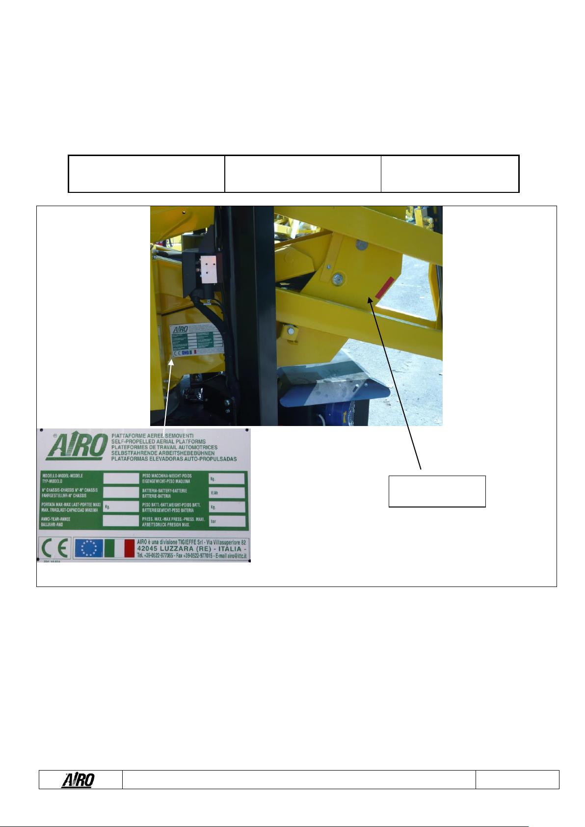
1.8. Identification
In order to identify the machine, when spare parts and service are required, always mention the information given in the serial
number plate. Should this plate (as well as the various stickers applied on the machine) be lost or illegible, it is to be replaced as
soon as possible. In order to identify the machine when no plate is available the serial number is also stamped on the chassis. To
locate the plate and the stamp of the serial number, see the following picture. It is recommended to copy such data in the following
boxes.
MODEL: _________________
CHASSIS: __________________
YEAR: __________________
Fig. 1
SC XXXXXX

Use and Maintenance Manual - R13 R17 Series
Page 11
1.9. Location of main components
The picture shows the machine and its own components.
1) Control panel
2) Electric control unit
3) Hydraulic control unit
4) Drive gear motors
5) Turret rotation hydraulic motor
6) (optional) 230V single-phase power plug
7) Spirit level for visual check of machine
levelling
8) First boom lifting cylinder
9) Second boom lifting cylinder
10) Jib lifting cylinder
11) Cage lifting cylinder
12) -
13) Heat motor fuel tank
14) Turntable
15) Cage
16) Tracks
17) Heat motor
18) Electric pump
19) Outriggers;
20) Outriggers articulated feet
21) Battery
22) Inclinometer
23) Battery key
24) Ground air inlet
25) Platform air inlet
26) Platform electric socket.
Fig. 2

Use and Maintenance Manual - R13 R17 Series
Page 12
2. TECHNICAL FEATURES OF STANDARD MACHINES
THE TECHNICAL FEATURES OF THE PRODUCTS IN THE FOLLOWING PAGES CAN BE MODIFIED
WITHOUT PRIOR NOTICE
2.1. Model R13 S
R13 S
Dimensions:
Maximum working height
13.3
m
43 ’7”
ft
Max. platform height
11.3
m
37’ 0”
ft
Max. outreach from turntable centre
6.7
m
21 ‘11”
ft
Turret rotation (not continuous)
320
°
320
°
Platform rotation
120
°
120
°
Maximum capacity (m)
120
Kg
265
lbs
Max. number of people on the platform (n) –indoors
1
1
Tool and material weight (me) ** –indoors
40
Kg
88
lbs
Max. number of people on the platform (n) –outdoors
1
1
Tool and material weight (me) ** –outdoors
40
Kg
88
lbs
Maximum drive height
0
0
Maximum dimensions of platform
0.69 x 0.64
m
2 ‘3”x 2’1”
ft
Max. hydraulic pressure
210
Bar
3045.7
psi
Max. pressure of lifting circuit
210
Bar
3045.7
psi
Tracks dimensions (****)
Ø 300 x 180
mm
Ø11.8” x 7.0”
in
Transport dimensions
4.48 x 0.82 x 2
m
14 ‘ 8”x 2 ‘8”
x 6 ‘6”
ft
Transport dimensions with retracted jib
N.A.
m
N.A.
ft
Machine weight (unloaded) (*)
N.A.
Kg
N.A.
lb
Stability limit:
Longitudinal inclination
0.5
°
0.5
°
Transversal inclination
0.5
°
0.5
°
Maximum wind speed (***)
12.5
m/s
28
mph
Maximum manual force:
200
N
45
lbf
Stabilization area (between the support centres)
2.95 x 2.95
m
9 ‘8” x 9 ‘8”
ft
Max. slope compensated by outriggers
6
°
6
°
Max. load per outrigger
N.A.
Kg
N.D.
lbs
Performance:
Max. drive speed
1.12
km/h
1
mph
Oil tank capacity
28
Lt.
7
gal
Gradeability
30
%
30
%
Gradeability for loading/unloading
22
%
22
%
Max. operating temperature
+50
°C
122
°F
Min. operating temperature
-20
°C
-4
°F
Gasoline motor
Motor type
Honda iGX440
Type
four-stroke
petrol
4-stroke, petrol
Max. motor power
9.5
kW
13
hp
Adjusted Power
9
kW
12
hp
Starter battery
12 / 55
V / Ah
12 / 55
V / Ah
Total electrolyte quantity
3
Lt.
1
gal
Fuel tank capacity
5.9
Lt.
1.5
gal
Max. drive speed
1.12
km/h
1
mph
Fuel type
Unleaded petrol,
octane >86
unleaded petrol;
octan >86
Fuel consumption at rated power
3.6
L/h @ 3600
rpm
1
gal/h @
3600
giri/min
Lubricant oil capacity
1.1
Lt.
0.29
gal
Lubricant oil capacity
SAE 10W-30
SAE 10W-30
Use and Maintenance Manual - R13 R17 Series
Page 13
Diesel Motor
Motor type
N.A.
N.A.
Type
N.A.
N.A.
Motor power
N.A.
kW
N.A.
hp
Starter battery
N.A.
V / Ah
N.A.
V / Ah
Fuel tank capacity
N.A.
Lt.
N.A.
gal
Max. drive speed
N.A.
km/h
N.A.
mph
Fuel type
N.A.
N.A.
Fuel consumption at rated power
N.A.
N.A.
Lubricant oil capacity
N.A.
Lt.
N.A.
gal
Lubricant oil capacity
N.A.
N.A.
230V single-phase electric pump
Motor type
Single-phase 230V
50Hz
single-
phase
230V
50Hz
Motor power
2.2
kW
3
hp
Max. absorbed current
14
A
14
A
Max. drive speed
0.72
km/h
0.4
mph
(*) In some cases different limits can be fixed. It is recommended to comply with the data shown on the machine plate.
( ** ) me = m –(n x 80)
(***) Wind speeds higher or equal to 12.5 m/s indicate that the machines can also be used outdoors; Wind speeds equal to 0 m/s indicate that the machines can
be used INDOORS ONLY.
( **** ) Standard black rubber tracks; Optional non-marking rubber tracks.

Use and Maintenance Manual - R13 R17 Series
Page 14
2.2. Model R13 DC
R13 DC
Dimensions:
Maximum working height
13.3
m
43 '7"
ft
Max. platform height
11.3
m
37 '
ft
Max. outreach from turntable centre
6.7
m
21 '7"
ft
Turret rotation (not continuous)
320
°
320
°
Platform rotation
120
°
120
°
Maximum capacity (m)
200
Kg
441
lbs
Max. number of people on the platform (n) –indoors
2
2
Tool and material weight (me) ** –indoors
40
Kg
88
lbs
Max. number of people on the platform (n) –outdoors
2
2
Tool and material weight (me) ** –outdoors
40
Kg
88
lbs
Maximum drive height
0
0
Maximum dimensions of platform
1.39 x 0.71
m
4 '6"x 2 '3"
ft
Max. hydraulic pressure
210
Bar
3045.9
psi
Max. pressure of lifting circuit
210
Bar
3045.9
psi
Tracks dimensions (****)
Ø 300 x 180
mm
Ø11.8"x 7.0"
in
Transport dimensions
4.55 x 1.39 x 2
m
15x5x7
ft
Transport dimensions (cage removed)
4.55 x 0.82 x 2
m
14 '11"x 2
'8"x6 '7"
ft
Transport dimensions with retracted jib
N.A.
m
N.A.
N.A.
Machine weight (unloaded) (*)
2150
Kg
4740
lbs
Stability limit:
Longitudinal inclination
0.5
°
0.5
°
Transversal inclination
0.5
°
0.5
°
Maximum wind speed (***)
12.5
m/s
28
mph
Maximum manual force:
400
N
90
lbf
Stabilization area (between the support centres)
2.95 x 2.95
m
10 x 10
lbs
Max. slope compensated by outriggers
6
°
6
°
Max. load per outrigger
900
Kg
1900
lb
Performance:
Max. drive speed
1.12
km/h
1
mph
Oil tank capacity
28
Lt.
7
gal
Gradeability
30
%
30
%
Gradeability for loading/unloading
22
%
22
%
Max. operating temperature
+50
°C
122
°F
Min. operating temperature
-20
°C
68
°F
Gasoline motor
Motor type
Honda iGX440
Honda
iGX440
Type
four-stroke petrol
4-stroke,
petrol
Max. motor power
9.5
kW
12.7
hp
Adjusted Power
9
kW
12
hp
Starter battery
12 / 55
V / Ah
12 / 55
V / Ah
Total electrolyte quantity
3
Lt.
0.9
gal
Fuel tank capacity
5.9
Lt.
1.55
gal
Max. drive speed
1.12
km/h
0.69
mph
Fuel type
Unleaded petrol,
octane >86
unleaded
petrol; octan
>86
Fuel consumption at rated power
3.6
L/h @
3600
rpm
1
gal/h @
3600
giri/min
Lubricant oil capacity
1.1
Lt.
0.29
gal
Lubricant oil type
SAE 10W-30
SAE 10W-
30

Use and Maintenance Manual - R13 R17 Series
Page 15
Diesel Motor
Motor type
N.A.
N.A.
Type
N.A.
N.A.
Motor power
N.A.
kW
N.A.
hp
Starter battery
N.A.
V / Ah
N.A.
V / Ah
Fuel tank capacity
N.A.
Lt.
N.A.
gal
Max. drive speed
N.A.
km/h
N.A.
mph
Fuel type
N.A.
N.A.
Fuel consumption at rated power
N.A.
N.A.
Lubricant oil capacity
N.A.
Lt.
N.A.
gal
Lubricant oil type
N.A.
N.A.
230V single-phase electric pump
Motor type
Single-phase 230V
50Hz
single-
phase
230V 50Hz
Motor power
2.2
kW
3
hp
Max. absorbed current
14
A
14
A
Max. drive speed
0.72
km/h
0.4
mph
(*) In some cases different limits can be fixed. It is recommended to comply with the data shown on the machine plate.
( ** ) me = m –(n x 80)
(***) Wind speeds higher or equal to 12.5 m/s indicate that the machines can also be used outdoors; Wind speeds equal to 0 m/s indicate that the machines can
be used INDOORS ONLY.
( **** ) Standard black rubber tracks; Optional non-marking rubber tracks.

Use and Maintenance Manual - R13 R17 Series
Page 16
Fig. 3

Use and Maintenance Manual - R13 R17 Series
Page 17
2.3. Model R17 S
R17 S
Dimensions:
Maximum working height
16.5
m
54 '1"
ft
Max. platform height
14.5
m
157 '5"
ft
Max. outreach from turntable centre
6.5
m
21 '3"
ft
Turret rotation (not continuous)
320
°
320
°
Platform rotation
120
°
120
°
Maximum capacity (m)
120
Kg
264
lbs
Max. number of people on the platform (n) –indoors
1
1
Tool and material weight (me) ** –indoors
40
Kg
88
lbs
Max. number of people on the platform (n) –outdoors
1
1
Tool and material weight (me) ** –outdoors
40
Kg
88
lbs
Maximum drive height
0
0
Maximum dimensions of platform
0.69 x 0.64
m
2 '3"x 2 '1"
ft
Max. hydraulic pressure
210
Bar
3045.7
psi
Max. pressure of lifting circuit
210
Bar
3045.7
psi
Tracks dimensions (****)
Ø 300 x 180
mm
Ø11.8" x
7.0"
in
Transport dimensions
4.45 x 0.82 x 2
m
14 '7"x2
'8"x6 '6"
ft
Transport dimensions with retracted jib
N.A.
m
N.A.
ft
Machine weight (unloaded) (*)
N.A.
Kg
N.D.
lbs
Stability limit:
Longitudinal inclination
0.5
°
0.5
°
Transversal inclination
0.5
°
0.5
°
Maximum wind speed (***)
12.5
m/s
28
mph
Maximum manual force:
200
N
45
lbf
Stabilization area (between the support centres)
2.95 x 2.95
m
9 '8"x 9 '8"
ft
Max. slope compensated by outriggers
6
°
6
°
Max. load per outrigger
N.A.
Kg
N.D.
lbs
Performance:
Max. drive speed
1.12
km/h
0.69
mph
Oil tank capacity
28
Lt.
7.39
gal
Gradeability
30
%
30
%
Gradeability for loading/unloading
22
%
22
%
Max. operating temperature
+50
°C
122
°F
Min. operating temperature
-20
°C
68
°F
Gasoline motor
Motor type
Honda iGX440
Type
four-stroke petrol
4-stroke
petrol
Max. motor power
9.5
kW
12.7
hp
Adjusted Power
9
kW
12
hp
Starter battery
12 / 55
V / Ah
12 / 55
V / Ah
Total electrolyte quantity
3
Lt.
0.9
gal
Fuel tank capacity
5.9
Lt.
1.5
gal
Max. drive speed
1.12
km/h
0.69
mph
Fuel type
Unleaded petrol,
octane >86
unleaded
petrol;
octan >86
Fuel consumption at rated power
3.6
L/h @
3600
rpm
1
gal/h @
3600
giri/min
Lubricant oil capacity
1.1
Lt.
0.29
gal
Lubricant oil type
SAE 10W-30
SAE 10W-
30

Use and Maintenance Manual - R13 R17 Series
Page 18
Diesel Motor
Motor type
N.A.
N.A.
Type
N.A.
N.A.
Motor power
N.A.
kW
N.A.
hp
Starter battery
N.A.
V / Ah
N.A.
V / Ah
Fuel tank capacity
N.A.
Lt.
N.A.
gal
Max. drive speed
N.A.
km/h
N.A.
mph
Fuel type
N.A.
N.A.
Fuel consumption at rated power
N.A.
N.A.
Lubricant oil capacity
N.A.
Lt.
N.A.
gal
Lubricant oil type
N.A.
N.A.
230V single-phase electric pump
Motor type
Single-phase 230V
50Hz
single-phase
230V 50Hz
Motor power
2.2
kW
2,9
hp
Max. absorbed current
14
A
14
A
Max. drive speed
0.72
km/h
0,44
mph
(*) In some cases different limits can be fixed. It is recommended to comply with the data shown on the machine plate.
( ** ) me = m –(n x 80)
(***) Wind speeds higher or equal to 12.5 m/s indicate that the machines can also be used outdoors; Wind speeds equal to 0 m/s indicate that the machines can
be used INDOORS ONLY.
( **** ) Standard black rubber tracks; Optional non-marking rubber tracks.

Use and Maintenance Manual - R13 R17 Series
Page 19
2.4. Model R17 DC
R17 DC
Dimensions:
Maximum working height
16.5
m
54 '1"
ft
Max. platform height
14.5
m
157 '5"
ft
Max. outreach from turntable centre
6.5
m
21
ft
Turret rotation (not continuous)
320
°
320
°
Platform rotation
120
°
120
°
Maximum capacity (m)
200
Kg
440.9
lbs
Max. number of people on the platform (n) –indoors
2
2
Tool and material weight (me) ** –indoors
40
Kg
88.1
lbs
Max. number of people on the platform (n) –outdoors
2
2
Tool and material weight (me) ** –outdoors
40
Kg
88.1
lbs
Maximum drive height
0
0
Maximum dimensions of platform
1.39 x 0.71
m
4 '6" x 2 '3"
ft
Max. hydraulic pressure
210
Bar
3045.7
psi
Max. pressure of lifting circuit
210
Bar
3045.7
psi
Tracks dimensions (****)
Ø 300 x 180
mm
Ø11.8" x 7.0"
in
Transport dimensions
4.52 x 1.39 x 2
m
14 '9"x4
'6"x6 '6"
ft
Transport dimensions (cage removed)
4.52 x 0.82 x 2
m
14 '9"x2
'8"x7
ft
Transport dimensions with retracted jib
N.A.
m
N.A.
ft
Machine weight (unloaded) (*)
2200
Kg
4850
lbs
Stability limit:
Longitudinal inclination
0.5
°
0,5
°
Transversal inclination
0.5
°
0,5
°
Maximum wind speed (***)
12.5
m/s
27.9
mph
Maximum manual force:
400
N
882
lbf
Stabilization area (between the support centres)
2.95 x 2.95
m
9 '8"x 9 '8"
ft
Max. slope compensated by outriggers
6
°
6
°
Max. load per outrigger
920
Kg
2000
lbs
Performance:
Max. drive speed
1.12
km/h
0.69
mph
Oil tank capacity
28
Lt.
7.39
gal
Gradeability
30
%
30
%
Gradeability for loading/unloading
22
%
22
%
Max. operating temperature
+50
°C
122
°F
Min. operating temperature
-20
°C
-68
°F
Gasoline motor
Motor type
Honda iGX440
Type
four-stroke petrol
4-stroke,
petrol
Max. motor power
9.5
kW
12.7
hp
Adjusted Power
9
kW
12
hp
Starter battery
12 / 55
V / Ah
12 / 55
V / Ah
Total electrolyte quantity
3
Lt.
0.79
gal
Fuel tank capacity
5.9
Lt.
1.5
gal
Max. drive speed
1.12
km/h
0.69
mph
Fuel type
Unleaded petrol,
octane >86
unleaded
petrol; octan
>86
Fuel consumption at rated power
3.6
L/h @
3600
rpm
1
gal/h @
3600
giri/min
Lubricant oil capacity
1.1
Lt.
0.29
gal
Lubricant oil type
SAE 10W-30
SAE 10W-30

Use and Maintenance Manual - R13 R17 Series
Page 20
Diesel Motor
Motor type
N.A.
N.A.
Type
N.A.
N.A.
Motor power
N.A.
kW
N.A.
hp
Starter battery
N.A.
V / Ah
N.A.
V / Ah
Fuel tank capacity
N.A.
Lt.
N.A.
gal
Max. drive speed
N.A.
km/h
N.A.
mph
Fuel type
N.A.
N.A.
Fuel consumption at rated power
N.A.
N.A.
Lubricant oil capacity
N.A.
Lt.
N.A.
gal
Lubricant oil capacity
N.A.
N.A.
230V single-phase electric pump
Motor type
Single-phase 230V
50Hz
single-phase
230V 50Hz
Motor power
2.2
kW
2,9
hp
Max. absorbed current
14
A
14
A
Max. drive speed
0.72
km/h
0,44
mph
(*) In some cases different limits can be fixed. It is recommended to comply with the data shown on the machine plate.
( ** ) me = m –(n x 80)
(***) Wind speeds higher or equal to 12.5 m/s indicate that the machines can also be used outdoors; Wind speeds equal to 0 m/s indicate that the machines can
be used INDOORS ONLY.
( **** ) Standard black rubber tracks; Optional non-marking rubber tracks.
This manual suits for next models
4
Table of contents
Other TIGIEFFE Lifting System manuals


Popular Lifting System manuals by other brands


PFlow Industries
PFlow Industries B Series Owner's, Installation and Maintenance Manual

SCANCLIMBER
SCANCLIMBER SC300K instruction manual

OMCN
OMCN 126/B INSTRUCTIONS FOR USE, MAINTENANCE AND SPARE PARTS

Greencut
Greencut ELA1000M instruction manual

The Handy
The Handy 16005G instructions

Guldmann
Guldmann Pontus 550371 manual


