SCANCLIMBER SC300K User manual

INSTRUCTION MANUAL
Serial number:________
SC400K
V71_12.08
Access Lift
OY SCANINTER NOKIA LTD
• Turkkirata 26 • 33960 PIRKKALA •
• Tel. +358 010 680 7000 • Fax +358 010 680 7033 • www.scanclimber.com
SC300K

2
C o v e r
V71_12.08
SC300K/SC400K Pos 0

3
C o v e r
V71_12.08 SC300K/SC400K Pos 0
1. GENERAL INFORMATION
1.1 Technical Data................................................................................3
1.1.1 General Technical Data ..........................................................3
1.1.2 Electrical System ......................................................................3
1.1.3 T
echnical Data for the Lift Car and the Lifting Mechanism
..........4
1.2 Lift Description .................................................................................5
1.2.1 Mechanical Structures.............................................................6
1.2.1.1 Lift Ground Station and Lift Shaft ................................6
1.2.1.2 Mast................................................................................7
1.2.1.3 Landings.........................................................................8
1.2.1.4 Lift Car............................................................................9
1.2.1.5 Safety Brake ................................................................10
1.2.1.6 Drive .............................................................................10
1.2.1.7 Door Opening/Locking System.................................10
1.2.1.8 Door Locking System ..................................................11
1.2.1.9 Load Control ...............................................................12
1.2.2 Electric System........................................................................13
1.2.2.1 General Description ...................................................13
1.2.2.2 Main Circuit .................................................................13
1.2.2.3 Control Circuit .............................................................13
1.2.2.4 Lift Car and Ground Station ......................................14
1.2.3 Safety Device..........................................................................16
1.2.4 Electric Safety Device............................................................17
1.2.5 Anchoring Forces...................................................................17
1.2.6 Bolt and Nut Tightening Torques ...........................................18
TABLE OF CONTENTS Page 1/4

4
C o v e r
SC300K/SC400K Pos 0 V71_12.08
2. SAFETY INSTRUCTIONS
2.1 General Information.................................................. 3
2.2 Before the Operation ................................................ 4
2.3 Operation .................................................................. 4
2.4 Service and Maintenance ....................................... 5
2.5 Instruction and Warning Decals .............................. 6
3. OPERATING INSTRUCTIONS
3.1 Prior to the Use .......................................................... 3
3.2 Operation of the Lift .................................................. 4
3.3 Closing the Operation .............................................. 5
3.4 Maintenance and Inspection Operations .............. 5
3.5 Operation during Breakdown .................................. 6
3.5.1 Operation during Power Cut ........................................6
3.5.2 Safety Brake ...................................................................7
3.5.3 Function of the Top Safety Limit Switch .......................8
3.5.4 Function of the Bottom Safety Limit Switch .................8
3.5.5 Car Stops between the Landings .................................9
TABLE OF CONTENTS Page 2/4

5
C o v e r
V71_12.08 SC300K/SC400K Pos 0
4. TROUBLE SHOOTING - When the Lift Does
not Move
4.1 General Information.....................................................3
4.2 Supply Voltage ..........................................................4
4.3 Safety Circuit ..............................................................5
4.4 Other Possible Reasons .............................................5
4.5 Errors – Trouble Shooting ...........................................6
4.5.1 “Visible Error”..................................................................6
4.5.2 “Invisible Error” ..............................................................6
4.5.3 Most Common Reasons for the Lift not Moving ..........7
TABLE OF CONTENTS Page 3/4
5. SERVICE AND MAINTENANCE
5.1 General Information ...........................................................3
5.2 Service......................................................................................3
5.3 Lubrication...................................................................6
5.3.1 Lift Lubrication Program ................................................6
5.3.2 Automatic Lubrication of the Gear Rack ....................7
5.3.3 Rack Lubrication Pump .................................................8
5.3.3.1 Lubrication interval Adjustment .......................8
5.4 Load Control 11
5.4.1 Control Card Layout ....................................................10
5.4.2 Load Control Calibration ............................................11
5.4.3 Load Control Automatic Calibration .........................12

6
C o v e r
SC300K/SC400K Pos 0 V71_12.08
5. SERVICE AND MAINTENANCE
5.5 Adjustments...............................................................13
5.5.1 Adjusting the Lifting Mechanism Pinion ....................13
5.5.2 Guide Roller Clearance ..............................................14
5.5.3 Replacing the Guide Rollers .......................................14
5.5.4 Safety Brake .................................................................15
5.5.4.1 Operation of the Safety Brake .......................15
5.5.4.2
Radial Clearance of the Safety Brake Bearings . . 16
5.5.4.3 Adjusting the Safety Brake Pinions .................16
5.5.4.4
Limit Values for the Lift Wearing Parts and Wear
....16
5.6 Safety Brake .............................................................18
5.6.1 When the Safety Brake has Switched on ..................18
5.6.2 Testing the Safety Brake .............................................20
5.6.2.1 1Correct Function of the Safety Brake ..........21
5.6.2.2 Incorrect Function of the Safety Brake .........22
5.6.3 Adjusting the Safety Brake .........................................22
6. ERECTION OF THE Lift
6. Erection of the Lift ................................................................3
TABLE OF CONTENTS Page 4/4

7
C o v e r
V71_12.08 SC300K/SC400K Pos 0
0. PREFACE
SCANCLIMBER® SC300K/SC400K
The purpose of this instruction manual is to give information on the lift’s characteristics
and its proper use.
The manual contains useful instructions on the safe, proper and economical operation
of the lift. These instructions help avoid risks, cut down operating costs and increase the
lift’s service life.
The instruction manual should always be available for those working with the lift and it
must not be removed from the lift car.
In addition to the requirements of this manual as well as those of the law and statutes, at-
tention must be paid also to the national and the site’s regulations on the safe and care-
ful use of the lift.

1
G e n e r a l i n f o r m a t i o n
V71_12.08 SC300K/SC400K Pos 1
1. GENERAL INFORMATION
1.1 Technical Data................................................................................3
1.1.1 General Technical Data ..........................................................3
1.1.2 Electrical System ......................................................................3
1.1.3 T
echnical Data for the Lift Car and the Lifting Mechanism
..........4
1.2 Lift Description .................................................................................5
1.2.1 Mechanical Structures.............................................................6
1.2.1.1 Lift Ground Station and Lift Shaft................................6
1.2.1.2 Mast................................................................................7
1.2.1.3 Landings.........................................................................8
1.2.1.4 Lift Car............................................................................9
1.2.1.5 Safety Brake ................................................................10
1.2.1.6 Drive .............................................................................10
1.2.1.7 Door Opening/Locking System.................................10
1.2.1.8 Door Locking System..................................................11
1.2.1.9 Load Control...............................................................12
1.2.2 Electric System........................................................................13
1.2.2.1 General Description...................................................13
1.2.2.2 Main Circuit.................................................................13
1.2.2.3 Control Circuit.............................................................13
1.2.2.4 Lift Car and Ground Station......................................14
1.2.3 Safety Device..........................................................................16
1.2.4 Electric Safety Device............................................................17
1.2.5 Anchoring Forces...................................................................17
1.2.6 Bolt and Nut Tightening Torques ...........................................18

2
G e n e r a l i n f o r m a t i o n
V71_12.08
SC300K/SC400K Pos 1

3
G e n e r a l i n f o r m a t i o n
V71_12.08 SC300K/SC400K Pos 1
1. General Information
1.1 Technical Data
SC300K SC400K
Payload 300 kg or 3 persons 400 kg or 4 persons
Speed 0,6 m/s 0,6 m/s
Lifting height
Max. free mast after topmost anchoring 1 m 1 m
Max. distance between anchors 3 m 3 m
Weight of the mast section 75 kg 75 kg
Weight of the lift car 830 kg 890 kg
Operation temperature -25°C…+40°C -25°C…+40°C
Noise level to the surroundings [dB (A)] Max. 80 dB Max. 80 dB
SC300K SC400K
Number of lifting motors 1 1
Motor rating 7,5 kW 9,2 kW
Starting current 100 A 120 A
Nominal power 8,0 kW 10 kW
Supply voltage 400V/50Hz 400V/50Hz
Lift control voltage 48V AC 48V AC
Socket voltage 230V AC 50Hz 230V AC 50Hz
Signal circuit voltage 24V DC 24V DC
Permissible voltage variation ± 5% ± 5%
Fault mode current protection
residual current device residual current device
1.1.2 Electrical System
1.1.1 General Technical Data

4
G e n e r a l i n f o r m a t i o n
V71_12.08
SC300K/SC400K Pos 1
Item Parameter Value SC300K Value SC400K
Car
(internal) Width 1043 mm 1270 mm
Length 775 mm 780 mm
Height 2100 mm
Weight 480 kg
Mast section Length 1508 mm
Mast pipe distance 650 mm
Mast bolts M20 x 230-10.9 - 4 pc./section
Electric motor Type 132M/4 - NORD
Nominal power 7,5 kW 9,2 kW
Rotation speed 1194 [1/min] 1450 [1/min]
Nominal voltage 400/690 V - 50 Hz
Nominal current 15,5 A 18 A
Weight 48 kg 66,0 kg
Brake Operating principle
Disk type, electro magnetically switched
Type BRE 100 SR HL BRE 150C SR HL
Moment 100Nm 75-150 Nm
Weight 16 kg 24.0 kg
Transmission Type SK 9042.1 VF
Transmission ratio 1:15,84 1:15,66
Weight 110 kg 135.0 kg
Liftingmechanism
pinion Module 6 mm
Number of teeth 20
Rotation speed 60 [1/min] 93 [1/min]
Safety brake Operating principle Sliding, centrifugal action
Type UC – 3.0 A
Releasing speed 0.9 m/s
Weight 32.5 kg
1.1.3 Technical Data for the Lift Car and the Lifting Mechanism

5
G e n e r a l i n f o r m a t i o n
V71_12.08 SC300K/SC400K Pos 1
Car
Mast
Wall anchor
Ground station
(Landing 0)
Landing 3
Landing 1
Landing 2
SC300K/SC400Kliftismeantfortrans-
portation of persons and materi-
als, among other things for mainte-
nance purposes, when working at
such industrial constructions as, for
instance, chimney stacks and vari-
ous towers. The lift is suitable for out-
door and indoor use. Also the lift’s
structure and material are resistant
toweathervariationsandretard the
inuence of corrosive materials. The
lift is a functional complex and con-
sists of the following main compo-
nents: ground station, lift car, lifting
mechanism,mastand landings. The
lift must be inspected as prescribed
by the law and regulations. Also the
periodicalmaintenance operations
recommendedbythemanufacturer
must be carried out.
1.2 Lift Description Safety buffer

6
G e n e r a l i n f o r m a t i o n
V71_12.08
SC300K/SC400K Pos 1
1.2.1.1
Lift Ground Station and Lift Shaft
The lift ground station and the frame built
under the mast are installed on a steel/
construction foundation. The shaft / well
undertheliftisabout1500 mm deep. At the
ground station (1), on the frame under the
mast there are 2 safety buffers (2), which
limit the lift car’s downward movement.
The safety buffers prevent in all cases the
descent of the lift car onto the well bottom
andleaveanecessaryspaceunderthecar.
The ground station forms a closed car like
structure with a door on its one side for the
access into the lift car. The ground station
frame and wall structures are galvanizing
steel.Thesizeofthegroundstationdoor’s(3)
freeopeningisabout
720x2000mmSC300K
/
780 x 2000 mm SC400K. The door structure
is a two-leafed door opening in the middle
towards the landing. The door is equipped
with a locking device (4), which allows the
door opening only when the car is at the
ground station. The door is opened manu-
ally. The door and the locking device are
controlled with limit switches. At the ground
station there also is a push button box for
calling the lift car.
1.2.1 Mechanical Structures
3
4
1
2

7
G e n e r a l i n f o r m a t i o n
V71_12.08 SC300K/SC400K Pos 1
1.2.1.2 Mast
The mast consists of mast sections with a
length of 1508 mm. The cross prole of the
mast sections forms a rectangle, hot galva-
nized, welded structure with square guide
pipesinthecorners.Theintervaloftheguide
pipesis650mm.Themast sections arejoined
to each other with four M20 – 10.9 bolts and
Nyloc nuts. The mast is fastened from the
bottom to the ground station frame struc-
ture and to the steel/construction founda-
tion under the lift. In addition the mast is
fastened to the wall structures. The anchor
interval of the mast is about 3 m. The mast
anchors are of hot galvanized steel. Two
safety buffers are xed to the top part of
the mast to its top section in order to limit
the lift’s upward movement.
wall anchor
mast section

8
G e n e r a l i n f o r m a t i o n
V71_12.08
SC300K/SC400K Pos 1
1.2.1.3 Landings
The landing doors (1) are two-leafed doors
opening in the middle towards the land-
ing. The landing door free opening is about
720x2000mmSC300K/780x2000mmSC400K.
The door is equipped with a locking device
(2), which allows the door opening only
when the lift car is by the landing doors.
The landing door is opened manually. The
landing doors and the locking device are
controlledwithlimitswitches. By the landing
doorstherealsoisapushbuttonboxforcall-
ing the car to the landing. Below the land-
ing door threshold there is a door opening
wide and 750 mm high kick plate (3).
1
2
3

9
G e n e r a l i n f o r m a t i o n
V71_12.08 SC300K/SC400K Pos 1
The size of the lift car is 775 x 1043 x 2100
SC300K / 780 x 1270 x 2100 SC400K (length x
widthxheight).Themax.permissiblepayload
is400kg or max. four (4)persons(SC400K)or
300 kg or max. three (3) persons (SC300K).
The lift speed is about 0.6 m/s (36 m/min).
The lift car forms a closed car like structure
withadooronitsonesideforthe access into
the lift car. The lift car frame structures are
hot galvanized steel and the wall structures
painted steel panel. The car door (1) struc-
tureisatwo-leafeddoor opening inwards in
themiddle. The size ofthedoor’s free open-
ing is about 720 x 2000 SC300K / 780 x 2000
SC400K.Thedoor is equipped withalocking
device (2), which allows the door opening
only when the car is at the ground station
or by the landing door. The door is opened
manually. The door and the locking device
are controlled with limit switches. Below the
landingdoorthresholdthereisadooropen-
ingwideand750 mm high kick plate (3).On
thecarroofthereisasized 400 x600mmroof
gate (4), through which there is access to
the car roof. On the roof there are 1100 mm
high safety railings (5) with an intermediate
bar and a 150 mm high kick plate (6).
1.2.1.4 Lift Car
1
3
4
6
5
2

10
G e n e r a l i n f o r m a t i o n
V71_12.08
SC300K/SC400K Pos 1
The lift’s lifting mechanism consists of one
bevel gear and a electric motor, and an
electromagnetic brake. The motor brake
hasa hand lever, whichin case of anemer-
gency can be used for opening the motor
brake to lower the lift car to the ground
station or the next landing for safe exit from
the car. The lifting mechanism is placed on
the car roof.
1.2.1.6 Drive
Thesafetybrake(1)isplaced
onthecarroof.Duringemer-
gency situations the safety
brake stops the lift’s down-
ward movement if the lift’s
speed becomes faster than
the release speed of the
safety brake which is 0.9
m/s.
1.2.1.5 Safety Brake
1.2.1.7 Door Opening/Locking System
1

11
G e n e r a l i n f o r m a t i o n
V71_12.08 SC300K/SC400K Pos 1
1.2.1.8 Door Locking System
Landing 0
Landing 3
Landing 1
Landing 2
Landing door
Car
5 mm
Safety locking device ZB-88
Car stopper or li-
mit stopper

12
G e n e r a l i n f o r m a t i o n
V71_12.08
SC300K/SC400K Pos 1
Sensor TP1000
The lift is equipped with a load control
device, which prevents the lift start if the lift
isoverloaded.Theload control device con-
sists of two sensors connected to an elec-
tronic control card.
1.2.1.9 Load Control

13
G e n e r a l i n f o r m a t i o n
V71_12.08 SC300K/SC400K Pos 1
• Normal mode (control from the car
and the landings)
• Service and control mode (control
from the car roof)
Thelift’ssupply voltage is 400V AC, 50Hz.Theliftissupplied from a system withthreephases,
zero and protective earth. The outlet in the switchboard supplying the lift should have a
32 A D-fuse (SC300K) / 40 A D-fuse (SC400K).
1.2.2.1 General Description
Main circuit
• Control circuits and safety circuit• Lift car lighting• Lift phone•
1.2.2.2 Main Circuit
• Input disconnecting switch
• Main circuit over current and short-cir-
cuit protectors
• Fault mode current protector
• Lift car main switch
1.2.2.3 Control Circuit
The control circuits are used to control, e.g. the lift movements, landing calls and the door
status. The control circuits use 230 VAC, 48 VAC and 24VDC voltage.
The safety circuit is an important part of the lift’s control circuit and is meant to ensure
that the lift is safe to use in all operation situations and does not cause any dangers for
the users. The following limit switches and contactor information are connected to the
lift’s safety circuit:
Emergency lowering system
• 1 phase socket for measuring device• and hand tools
• Main contactors, 2 pieces series
connection
• Lifting motor circuit breaker
• Lifting motor brake contactors
• Testing the safety brake (control from
the ground station with a special
control device)
The lift has three different control modes which can be selected depending on the situa-
tion:
1.2.2 Electric System
This manual suits for next models
1
Table of contents
Other SCANCLIMBER Lifting System manuals
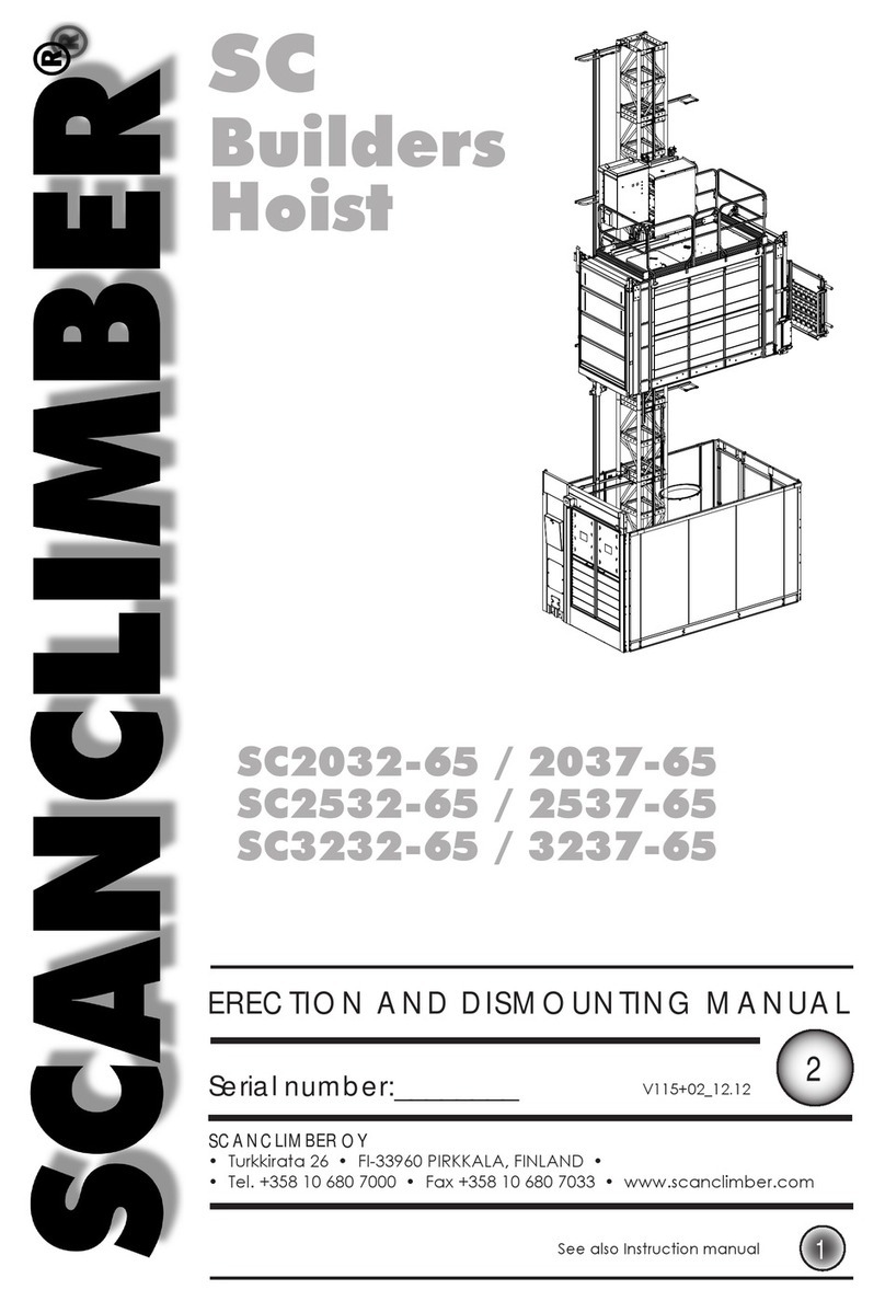
SCANCLIMBER
SCANCLIMBER SC2032-65 User manual

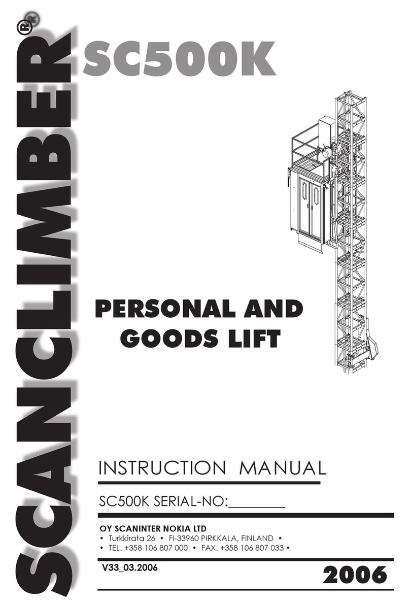
SCANCLIMBER
SCANCLIMBER SC500K User manual

SCANCLIMBER
SCANCLIMBER SC1300 User manual

SCANCLIMBER
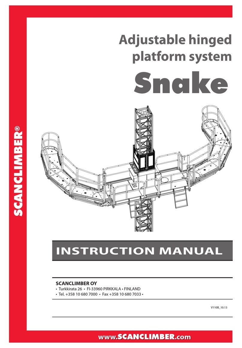
SCANCLIMBER Snake User manual
SCANCLIMBER
SCANCLIMBER LT500 User manual
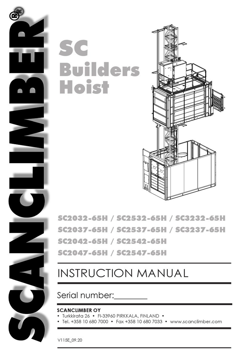
SCANCLIMBER
SCANCLIMBER 65H Series User manual
SCANCLIMBER
SCANCLIMBER SC4000 User manual

SCANCLIMBER
SCANCLIMBER SC2000K User manual