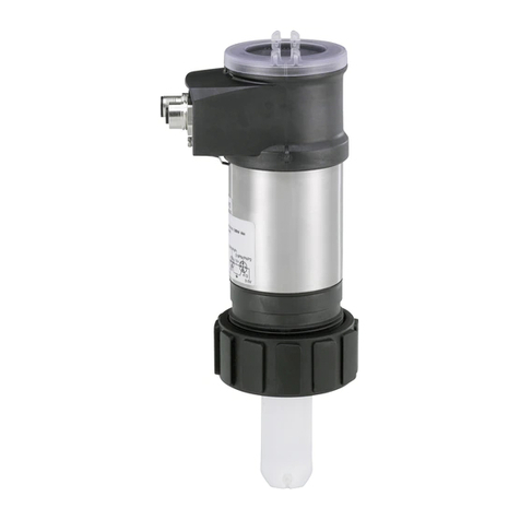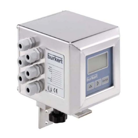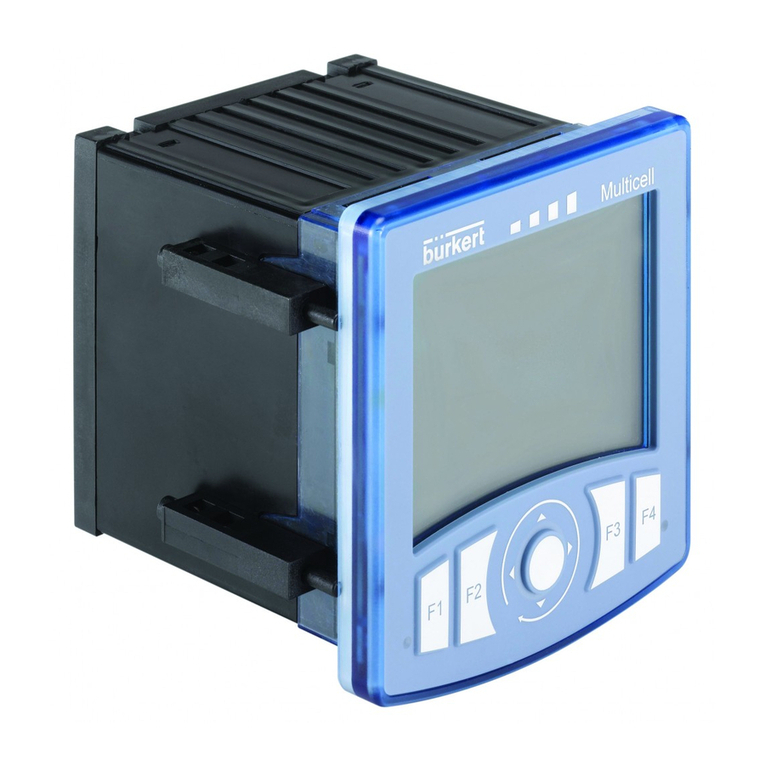
CONDUCTIVITY 8225
8225 E-1-
TABLE OF CONTENTS
1 INTRODUCTION ....................................................................................................................E-2
1.1 Unpacking and Control.............................................................................................................................................. E-2
1.2 About this Manual...................................................................................................................................................... E-2
1.3 User's Responsibility for Safety ................................................................................................................................ E-2
1.4 Electromagnetic compatibility .................................................................................................................................. E-2
2 SPECIFICATION ....................................................................................................................E-3
2.1 Type specifications short distance ........................................................................................................................... E-3
2.1.1 Conductivity transmitter type 8225 short distance .......................................................................................... E-3
2.1.2 Sensor designation type 8220 short distance ................................................................................................. E-3
2.2 Type specifications long distance ............................................................................................................................. E-4
2.2.1 Conductivity transmitter type 8225 long distance ........................................................................................... E-4
2.2.2 Sensor designation type 8220 long distance .................................................................................................. E-4
2.3 8220 Sensor measuring range ................................................................................................................................. E-5
2.4 Design and Measuring Principle ............................................................................................................................... E-6
2.5 Technical Data .......................................................................................................................................................... E-7
3 INSTALLATION ......................................................................................................................E-8
3.1 Installation Guidelines ............................................................................................................................................... E-8
3.2 8220 Sensor installation............................................................................................................................................ E-8
3.3 Transmitter installation .............................................................................................................................................. E-9
3.3.1 Panel version .................................................................................................................................................. E-9
3.3.2 Wall-mounted version installation ................................................................................................................. E-10
3.4 Electrical connection ............................................................................................................................................... E-10
3.4.1 General electrical requirements .................................................................................................................... E-10
3.4.2 Connection of 4-20 mA output to a PLC ....................................................................................................... E-11
3.5 Electrical wiring 8225 Transmitter Short distance ................................................................................................ E-11
3.5.1 Connection of the 8220 Sensor to the 8225 Transmitter ............................................................................. E-11
3.5.2 8225 Transmitter panel version without relay ............................................................................................... E-12
3.5.3 8225 Transmitter panel version with relays .................................................................................................. E-13
3.5.4 8225 Transmitter wall-mounted version 12-30 VDC .................................................................................... E-14
3.5.5 8225 Transmitter wall-mounted version 115-230 VAC ................................................................................. E-15
3.6 Electrical wiring 8225 Transmitter long distance .................................................................................................. E-15
3.6.1 Connection of the 8220 Sensor to the 8225 Transmitter ............................................................................. E-16
3.6.1 8225 Transmitter panel version without relay ............................................................................................... E-16
3.6.2 8225 Transmitter panel version with relays .................................................................................................. E-16
3.6.3 8225 Transmitter wall-mounted version 12-30 VDC .................................................................................... E-17
3.6.4 8225 Transmitter wall-mounted version 115-230 VAC ................................................................................. E-18
4 OPERATION ........................................................................................................................ E-19
4.1 Transmitter Operating and Control Elements ........................................................................................................ E-19
4.2 Operation Mode Display ......................................................................................................................................... E-20
4.3 Calibration Mode ..................................................................................................................................................... E-21
4.3.1 Language ....................................................................................................................................................... E-21
4.3.2 Engineering Units ........................................................................................................................................... E-22
4.3.3 Cell Constant .................................................................................................................................................. E-22
4.3.4 Temperature-Compensation Coefficient ....................................................................................................... E-24
4.3.5 Output Current ............................................................................................................................................... E-24
4.3.6 Relay .............................................................................................................................................................. E-24
4.3.7 Filter Function ................................................................................................................................................ E-24
4.4 Test Menu ................................................................................................................................................................ E-26
4.4.1 Offset-Compensation ..................................................................................................................................... E-26
4.4.2 Span-Compensation ...................................................................................................................................... E-27
4.4.3 Display of non-compensated Conductivity .................................................................................................... E-27
4.4.4 Conductivity-Simulation ................................................................................................................................. E-27
5 MAINTENANCE ................................................................................................................... E-28
5.1 Storing and Cleaning of the Electrode ................................................................................................................... E-28
5.2 Trouble-shooting ..................................................................................................................................................... E-28
5.3 Factory-settings of 8225 Transmitter at delivery .................................................................................................... E-28
5.4 Spare parts .............................................................................................................................................................. E-29
APPENDIX ................................................................................................................................... G-1
Dimensions ................................................................................................................................................................G-1
Examples of connection conductivity transmitter type 8225 ...................................................................................G-4

