Icom VHF IC-F50 User manual

INSTRUCTION MANUAL
This device complies with Part 15 of
the FCC rules. Operation is subject
to the condition that this device does
not cause harmful interference.
UHF TRANSCEIVER
iF60
VHF TRANSCEIVER
iF50

i
SAFETY TRAINING INFORMATION
Your Icom radio generates RF electromagnetic energy
during transmit mode. This radio is designed for and clas-
sified as “Occupational Use Only”, meaning it must be
used only during the course of employment by individu-
als aware of the hazards, and the ways to minimize such
hazards. This radio is NOT intended for use by the “Gen-
eral Population” in an uncontrolled environment.
This radio has been tested and complies with the FCC RF exposure lim-
its for “Occupational Use Only”. In addition, your Icom radio complies with
the following Standards and Guidelines with regard to RF energy and
electromagnetic energy levels and evaluation of such levels for exposure
to humans:
•FCCOETBulletin65Edition97-01SupplementC,EvaluatingCom-
pliance with FCC Guidelines for Human Exposure to Radio Fre-
quency Electromagnetic Fields.
•AmericanNationalStandardsInstitute(C95.1-1992),IEEEStandard
for Safety Levels with Respect to Human Exposure to Radio Fre-
quencyElectromagneticFields,3kHzto300GHz.
•AmericanNationalStandardsInstitute(C95.3-1992),IEEERecom-
mended Practice for the Measurement of Potentially Hazardous Elec-
tromagnetic Fields– RF and Microwave.
•The following accessories are authorized for use with this product.
Use of accessories other than those specified may result in RF ex-
posure levels exceeding the FCC requirements for wireless RF expo-
sure.;BeltClip(MB-98),RechargeableLi-ionBatteryPack(BP-227),
AlkalineBatteryCase(BP-226)andSpeaker-microphone(HM-138).
To ensure that your expose to RF electromagnetic
energy is within the FCC allowable limits for occu-
pational use, always adhere to the following guide-
lines:
CAUTION
WARNING

ii
SAFETY TRAINING INFORMATION
•DO NOT operate the radio without a proper antenna attached, as this
may damaged the radio and may also cause you to exceed FCC RF
exposure limits. A proper antenna is the antenna supplied with this
radio by the manufacturer or antenna specifically authorized by the
manufacturer for use with this radio.
•DO NOTtransmitformorethan50%oftotalradiousetime(“50%
dutycycle”).Transmittingmorethan50%ofthetimecancauseFCC
RF exposure compliance requirements to be exceeded. The radio is
transmitting when the TX indicator lights red.You can cause the radio
to transmit by pressing the “PTT” switch.
•ALWAYS keeptheantennaatleast2.5cm(1inch)awayfromthe
body when transmitting and only use the Icom belt-clip which is listed
on page i when attaching the radio to your belt, etc., to ensure FCC
RF exposure compliance requirements are not exceeded. To provide
the recipients of your transmission the best sound quality, hold the
antennaatleast5cm(2inches)fromyourmouth,andslightlyoffto
one side.
The information listed above provides the user with the information
needed to make him or her aware of RF exposure, and what to do to
assure that this radio operates with the FCC RF exposure limits of this
radio.
Electromagnetic Interference/Compatibility
During transmissions, your Icom radio generates RF energy that can pos-
sibly cause interference with other devices or systems. To avoid such in-
terference, turn off the radio in areas where signs are posted to do so. DO
NOT operate the transmitter in areas that are sensitive to electromagnetic
radiation such as hospitals, aircraft, and blasting sites.
Occupational/Controlled Use
The radio transmitter is used in situations in which persons are exposed
as consequence of their employment provided those persons are fully
aware of the potential for exposure and can exercise control over their
exposure.

iii
FOREWORD
READ ALL INSTRUCTIONS carefully and completely before
using the transceiver.
SAVE THIS INSTRUCTION MANUAL— This instruction
manualcontainsimportantoperatinginstructionsfortheIC-F50
v h f t r a n s c e i v e r andIC-F60u h f t r a n s c e i v e r .
EXPLICIT DEFINITIONS
WORD DEFINITION
RDANGER! Personal death, serious injury or an explo-
sion may occur.
RWARNING! Personal injury, fire hazard or electric shock
may occur.
CAUTION Equipment damage may occur.
NOTE
If disregarded, inconvenience only. No risk
of personal injury, fire or electric shock.
OPERATING NOTES
•Whentransmittingwitha portableradio,holdtheradioinavertical
positionwithitsmicrophone5to10centimeters(2to4inches)away
fromyourmouth.Keeptheantennaatleast2.5cm(1inch)fromyour
head and body.
•Ifyouwearaportabletwo-wayradioonyourbody,ensurethatthe
antennaisatleast2.5cm(1inch)fromyourbodywhentransmitting.
Icom, Icom Inc. and the Icom logo are registered trademarks of Icom Incorpo-
rated(Japan)inJapan,theUnitedStates,theUnitedKingdom,Germany,France,
Spain, Russia and/or other countries.

iv
PRECAUTIONS
RDANGER! NEVER short the terminals of the battery pack.
RDANGER! Use and charge only specified Icom battery packs with
Icom radios or Icom chargers. Only Icom battery packs are tested and
approved for use with Icom radios or charged with Icom chargers. Using
third-party or counterfeit battery packs or chargers may cause smoke,
fire, or cause the battery to burst.
RWARNING! NEVER hold the transceiver so that the antenna is very
close to, or touching exposed parts of the body, especially the face or eyes,
while transmitting. The transceiver will perform best if the microphone is 5
to10cm(2to4inches)awayfromthelipsandthetransceiverisvertical.
RWARNING!
NEVER operate the transceiver with a headset or
other audio accessories at high volume levels.
CAUTION: NEVER connect the transceiver to a power source other
than the specified battery pack or case. Such a connection will ruin the
transceiver.
DO NOT push the PTT when not actually desiring to transmit.
DO NOT use or place the transceiver in direct sunlight or in areas with
temperaturesbelow–30°C(–22°F)orabove+60°C(+140°F).
DO NOT modify the transceiver for any reason. The transceiver war-
ranty does not cover any problems caused by unauthorized modification.
MAKE SURE the flexible antenna and battery pack are securely at-
tached to the transceiver, and that the antenna and battery pack are dry
before attachment. Exposing the inside of the transceiver to water will
result in serious damage to the transceiver.
BE CAREFUL! ThetransceivermeetsIP67*requirementsfordust-
tight and waterproof protection. However, once the transceiver has been
dropped, dust-tight and waterproof protection cannot be guaranteed be-
cause of possible damage to the transceiver’s case or the waterproof seal.
*Onlywhenthebatterypackandjackcoverareattached.
FCC CAUTION: Changes or modifications to this device, not ex-
pressly approved by Icom Inc., could void your authority to operate this
transceiver under FCC regulations.

TABLEOFCONTENTS
v
SAFETY TRAINING INFORMATION............................................................i
FOREWORD .............................................................................................. iii
EXPLICIT DEFINITIONS............................................................................ iii
OPERATING NOTES.................................................................................. iii
PRECAUTIONS..........................................................................................iv
TABLEOFCONTENTS...............................................................................v
SUPPLIED ACCESSORIES....................................................................... vi
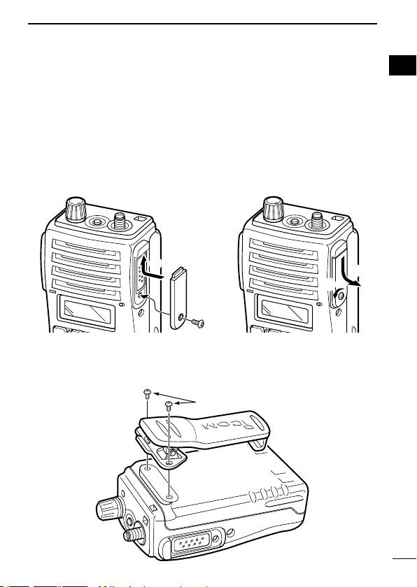
1 ACCESSORIES ................................................................................ 1−2
■ Accessory attachments ......................................................................1
2 PANEL DESCRIPTION................................................................... 3−11
■ Front, top and side panels..................................................................3
■ Function display .................................................................................5
■ Programmable function keys..............................................................6
3 CONVENTIONAL OPERATION ................................................... 12−18
■ Turning power ON.............................................................................12
■ Channel selection.............................................................................12
■ Call procedure ..................................................................................13
■ Receiving and transmitting ...............................................................14
■ Scrambler function ...........................................................................17
■ User Set mode .................................................................................18
4 BIIS OPERATION ......................................................................... 19−33
■ Default setting ..................................................................................19
■ Receiving a call ................................................................................20
■ Transmitting a call.............................................................................23
■ Receiving a message .......................................................................26
■ Transmitting a status.........................................................................29
■ Transmitting an SDM ........................................................................30
■ Position data transmission................................................................31
■ Printer connection ............................................................................31
■ PC connection ..................................................................................32
■BIISANI............................................................................................32
■ Auto emergency transmission ..........................................................32
■ Stun function ....................................................................................33
■BIISindication ..................................................................................33
■ Priority A channel selection ..............................................................33
5 MDC 1200 OPERATION............................................................... 34−42
■MDC1200systemoperation............................................................34
■ Transmitting a call.............................................................................35
■ Receiving a call ................................................................................41

vi
TABLEOFCONTENTS
SUPPLIED ACCESSORIES
The following accessories are supplied: Qty.
•Flexibleantenna .........................................1
•Batterypack ............................................1
•Jackcover .............................................1
•Beltclip................................................1
•Functionnamestickers*(KEY-STICKER) .....................1
*
There are no names on the programmable function keys since the func-
tionscanbefreelyassignedto[P0]to[P3],[Red],[ ]and[ ]keys.
Attach the supplied function name stickers above the appropriate keys for
easy recognition of that key’s assigned function.
VersionsoftheIC-F50/F60whichdisplaythe“FMAP-
PROVED” symbol as at left on the serial number seal, con-
formtointrinsically saferatingsoftheFMRC(Factory
MutualResearchCorporation).
Intrinsically safe : Class I, II, III, Division 1, Groups C, D, E, F, G
Nonincendive :ClassI,Division2,GroupsA,B,C,D
Connectedbatterypack :BP-227FM
The repair and maintenance of an FM approved transceiver can only be per-
formed in an Factory Mutual approved repair facility. The FM approval will be
canceled if FM intrinsically safe radios are repaired anywhere else except in an
approved facility.
6 BATTERY CHARGING ................................................................. 43−52
■Batterycharging ...............................................................................43
■ Caution.............................................................................................44
■ Optional battery chargers .................................................................45
■ Optional battery case .......................................................................51
7 SPEAKER-MICROPHONE........................................................... 53−54
■OptionalHM-138description............................................................53
■ Attachment .......................................................................................54
8 OPTIONS...................................................................................... 55−56

1
1ACCESSORIES
■Accessory attachments
DFlexible antenna
Connect the supplied flexible antenna
to the antenna connector.
CAUTION:
•NEVER carry the transceiver by
holding only the antenna.
•DO NOT connect the anntena
otherthanlistedonpage56.
•Transmitting without an antenna
may damage the transceiver.
DBattery pack
To attach the battery pack:
Slide the battery pack on the back of the transceiver in the direction
ofthearrow(q),thenlockitwiththebatteryreleasebutton.
•Slidethebatterypackuntilthebatteryreleasebuttonmakesaclick’
sound.
To remove the battery pack:
Push the battery release button
inthedirectionofthearrow(w)
as shown to the right. The bat-
tery pack is then removed.
NOTE: Keep the battery ter-
minals clean. It’s a good idea
to occasionally clean them.
NEVER remove or attach the battery pack when the transceiver
is wet or soiled. This may result water or dust getting into the
transceiver/battery pack and may result in the transceiver being
damaged.
q
w
Battery pack
Battery release button

1
ACCESSORIES
1
DJack cover
Attach the jack cover when the optional speaker-microphone is not
used.
To attach the jack cover:
qInsert the jack cover into the
[SPMIC]connector.
wTighten the screw.
To detach the jack cover:
eRemove the screw with a
phillips screwdriver.
rDetach the jack cover for the
speaker-microphone con-
nection.
q
w
e
r
DBelt clip
Attach the belt clip to the back of the transceiver with the supplied
screws.
Supplied screws
2

3
2PANEL DESCRIPTION
■Front, top and side panels
Microphone
Function display
(p. 6)
Speaker
(See the following
NOTE.)
q
i
u
w
e
r
t
y
NOTE: Ifthespeakernetting(fordustproong)becomeswet,
dryitwithahairdrier(coolmode)etc.beforeoperatingthe
transceiver. Otherwise the audio may be difficult to hear for loss
of the sound pressure.
qVOLUME CONTROL [VOL]
Turns power ON and adjusts the audio level.
wRED BUTTON
The desired function can be assigned by your dealer.
eANTENNA CONNECTOR
Connects the supplied antenna.

4
2
PANEL DESCRIPTION
2
rSPEAKER-MICROPHONE CONNECTOR [SP MIC]
Connectstheoptionalspeaker-microphone.(p.54)
[SP MIC] jack cover
NOTE: KEEP the [SP MIC]
jack cover attached to the
transceiver when the speaker-
microphone is not used.
(See page 2 for details)
tDEALER-PROGRAMMABLE KEYS [P0] to [P3]
The desired functions can be assigned independently by your
dealer.
yCH UP AND DOWN KEYS [ ]/[ ]
➥
During standby condition, push to select an operating channel.
➥Afterpushing[TXCodeCHSelect],pushtoselectaTXcode
channel.
➥
Afterpushing[DTMFAutodial],pushtoselectaDTMFchannel.
➥Afterpushingandholding[ScanAStart/Stop]/[ScanBStart/
Stop],pushtoselectascangroup.
➥Afterpushing[Digital],pushtoselectaBIIScode,status
number or SDM.
*Desiredfunctionscanbeassignedindependentlybyyourdealer.
uTRANSMIT/BUSY INDICATOR
Lights red while transmitting; lights green while receiving a sig-
nal, or when the squelch is open.
iPTT SWITCH [PTT]
Push and hold to transmit; release to receive.

5
2PANEL DESCRIPTION
■Function display
ru
y
i
t
e
w
q
qOUTPUT POWER INDICATOR
AppearswhenLow2orLow1isselected.
wAUDIBLE INDICATOR
➥Appearswhenthechannelisinthe‘audible’(unmute)condi-
tion.
➥Appearswhenthespecied2/5-tone/BIIScodeisreceived.
eCOMPANDER INDICATOR
Appears when the compander function is activated.
rKEY LOCK INDICATOR
Appears during the key lock function ON.
tSCRAMBLER INDICATOR
Appears when the voice scrambler function is activated.
yBELL INDICATOR
Appears/blinkswhenthespecic2/5-tone/BIIScodeisreceived,
according to the programming.
uBATTERY INDICATOR
Appears or blinks when the battery power decreases to a speci-
fied level.
iALPHANUMERIC DISPLAY
Displays the operating channel number, channel names, Set
mode contents, DTMF numbers, etc.

6
2
PANEL DESCRIPTION
2
■Programmable function keys
The following functions can be assigned to [P0], [P1], [P2], [P3],
[Red], []and [ ] programmable function keys.
Consult your Icom dealer or system operator for details concerning
your transceivers programming.
If the programmable function names are bracketed in the follow-
ing explanations, the specific switch used to activate the function
depends on programming.
CH UP AND DOWN KEYS
•Selectanoperatingchannel.
•Selectatransmitcodechannelafterpushingthe[TXCodeCH
Select]keys.
•SelectaDTMFchannelafterpushingthe[DTMFAutodial]key.
•Selectascangroupafterpushingandholdingthe[ScanAStart/
Stop]/[ScanBStart/Stop]keys.
•Select a BIIScode,statusnumberor SDMafterpushingthe
[Digital]key.
•PushtoselecttheMDCmenuafterpushing[MDCCALL].
•Pushtoselectthedesiredtransceiveraliasormessagechan-
nel while in the transceiver alias or message channel selection
mode.
BANK SELECT KEY
Pushthiskey,thenpush[CHUp]or[CHDown]toselectthede-
sired bank.
SCAN START/STOP KEYS
➥Push this key to start scanning; and push again to stop.
➥Push and hold this key to indicate the scan group, then select
thedesiredscangroupusing[CHUp]/[CHDown].
SCAN TAG KEY
Adds or deletes the selected channel to the scan group.

7
2PANEL DESCRIPTION
PRIORITY CHANNEL KEYS
➥PushtoselectPriorityAorPriorityBchannel.
➥Pushandhold[PrioA(Rewrite)]torewritethePrioAchannel.
MR-CH 1/2/3/4 KEYS
Select an operating channel directly.
MONITOR KEY
➥MuteandreleasetheCTCSS(DTCS)or2-tonesquelchmute.
Open any squelch/deactivate any mute while pushing this key.
(LMRoperationonly)
➥Activatesoneof(ortwoof)thefollowingfunctionsoneachchan-
nel independently: (PMRorBIISPMRoperationonly)
•Pushandholdtoun-mutethechannel(audioisemitted;‘Audible’
condition).
•Pushtomutethechannel(setsto‘Inaudible’only).
•Pushtoun-mutethechannel(setsto‘Audible’only).
•Pushafterthecommunicationisnishedtosenda‘resetcode’.
NOTE:Theun-mutecondition(‘Audible’condition)mayauto-
maticallyreturntothemutecondition(‘Inaudible‘condition)
after a specified period.
LOCK KEY
Push and hold to electronically lock all programmable keys except
the following:
[Call](incl.CallAandCallB),[Moni(Audi)]and[Emergency]keys.
OUTPUT POWER SELECTION KEY
Select the transmit output power temporarily or permanently, de-
pending on the pre-setting.
•Askyourdealerfortheoutputpowerlevelforeachselection.

8
2
PANEL DESCRIPTION
2
C.TONE CHANNEL ENTER KEY
Selectthecontinuoustonechannelusing[CHUp]/[CHDown]keys
to change the tone frequency/code setting after pushing this key for
permanent operation.
TALK AROUND KEY
Turn the talk around function ON and OFF.
•Thetalkaroundfunctionequalizesthetransmitfrequencytothere-
ceive frequency for transceiver-to-transceiver communication.
WIDE/NARROW KEY
Push to toggle the IF bandwidth between wide and narrow.
•Thewidepassbandwidthcanbeselectedfrom25.0or20.0kHzusing
theCS-F50cloning software.(PMRorBIISPMRoperationonly)
Ask your dealer for details.
DTMF AUTODIAL KEY
➥Push to enter the DTMF channel selection mode. Then select
thedesiredDTMFchannelusing[CHUp]/[CHDown]keys.
➥After selecting the desired DTMF channel, push this key to trans-
mit the DTMF code.
DTMF RE-DIAL KEY
Push to transmit the last-transmitted DTMF code.
CALL KEYS
Pushtotransmita2/5-tone/BIISIDcode.
•Calltransmissionisnecessarybeforeyoucallanotherstationdepend-
ing on your signalling system.
•The[CallA]and/or[CallB]keysmaybeavailablewhenyoursystem
employs selective ‘Individual/Group’ calls. Ask your dealer which call
is assigned to each key.

9
2PANEL DESCRIPTION
EMERGENCY KEYS
➥Push and hold to transmit an emergency call.
➥When[EmergencySingle(Silent)]or[EmergencyRepeat(Si-
lent)]ispushed,anemergencycallistransmittedwithoutabeep
emission and LCD indication change.
•Ifyouwanttocanceltheemergencycall,push(orpushandhold)
the key again before transmitting the call.
•Theemergencycallistransmittedonetimeonlyorrepeatedlyuntil
receiving a control code depending on the pre-setting.
TX CODE ENTER KEY (PMRorBIISPMRoperationonly)
Push to enter the direct ID code edit mode, for both 5-tone and
MSK. Then set the desired digit using [CH Up]/[CH Down]/
[TXCodeCHUp]/[TXCodeCHDown].(p.16)
TX CODE CHANNEL SELECT KEY
➥Push to enter the direct ID code channel selection mode. Then
setthedesiredchannelusing[CHUp]/[CHDown]/[TXCodeCH
Up]/[TXCodeCHDown].(p.15)
➥While in ID code channel selection mode, push for 1 sec. to enter
the ID code edit mode for 5-tone and MSK. Then set the desired
digitusing[CHUp]/[CHDown]/[TXCodeCHUp]/[TXCodeCH
Down].(p.16)
TX CODE CHANNEL UP/DOWN KEYS
Push to select a TX code channel directly.
ID MEMORY READ KEY (PMRorBIISPMRoperationonly)
➥Recalls detected ID codes.
•Pushthiskey,thenpush[CHUp]/[CHDown]forselection.
•Upto5ID’sarememorized.
➥Push and hold to erase the selected memorized ID’s.

10
2
PANEL DESCRIPTION
2
VOICE SCRAMBLER FUNCTION
Push to toggle the voice scrambler function ON and OFF.
COMPANDER KEY
Push to toggle the compander function ON and OFF.
The compander function reduces noise components from the trans-
mitting audio to provide clear communication.
USER SET MODE KEY
➥Push and hold to enter the User Set mode.
•DuringtheUserSetmode,pushthiskeytoselectanitem,and
push[CHUp]/[CHDown]tochangethevalueorcondition.
➥Push and hold this key again to exit the User Set mode.
DIGITAL KEY (BIISoperationonly)
➥Push to select the call ID list, transmit message and standby
condition. Toggles between queue channel and received mes-
sage record indication after queue channel is selected.
➥Push and hold to select queue channel indication.
STATUS UP/DOWN KEYS (BIISoperationonly)
➥While in the standby condition, push to display the transmit sta-
tus indication and select a status number.
➥When a received SDM is displayed, push to cancel the automatic
scroll and scroll the message manually.
➥WhenanSDMthatcontainsmorethan8charactersisdisplayed,
push to scroll the message manually.

11
2PANEL DESCRIPTION
MDC CALL KEY (MDCoperationonly)
➥Push to enter the MDC menu selection mode. Then select
the desired MDC menu from “SELCALL,” “MSG,” “STATUS,”
“RADIOCHK”and“CALALERT”using[CHUp]/[CHDown]/
[MDCUp]/[MDCDown].
After selection, push this key again to enter the transceiver
alias or message channel selection mode.
➥While in the transceiver alias or message channel selection
mode, push to return to the MDC menu selection mode.
MDC UP AND DOWN KEYS (MDCoperationonly)
➥PushtoselecttheMDCmenuafterpushing[MDCCALL].
➥Push to select the desired transceiver alias or message chan-
nel while in the transceiver alias or message channel selec-
tion mode.
MDC SELCALL KEY (MDCoperationonly)
Push to enter the transceiver alias selection mode.
•Afterthedesiredaliasselection,push[PTT]totransmitaselectivecall.
MDC CALLALERT KEY (MDCoperationonly)
Push to enter the transceiver alias selection mode.
•Afterthedesiredaliasselection,push[PTT]totransmitacallalert.

12
3
CONVENTIONAL OPERATION
2
3
■Turning power ON
qRotate[VOL]toturnpowerON.
wIf the transceiver is programmed for a start up passcode, input
digit codes as directed by your dealer.
•Thekeysinthetablebelowcanbeusedforpasswordinput:
•Thetransceiverdetectsnumbersinthesameblockasidentical.
Therefore“01234”and“56789”arethesame.
KEY
NUMBER 0
5
4
9
3
8
2
7
1
6
eWhen the “PASSWORD” indication does not clear after inputting
4digits,theinputcodenumbermaybeincorrect.Turnthepower
off and start over in this case.
■Channel selection
Several types of channel selections are available. Methods may dif-
fer according to your system set up.
NON-BANK TYPE:
Push [ ]/[ ]toselectthedesiredoperatingchannel,inse-
quence;or,pushoneofthe[MR-CH1]to[MR-CH4]keystoselect
a channel directly.
BANK-TYPE:
Push[Bank],thenpush[ ]or[ ]toselectthedesiredbank.
AUTOMATIC SCAN TYPE:
Channel setting is not necessary for this type. When turning the
power ON, the transceiver automatically starts scanning. Scanning
stops when receiving a call.

13
3CONVENTIONAL OPERATION
■Call procedure
Whenyoursystememploystonesignalling(excludingCTCSSand
DTCS),thecallproceduremaybenecessarypriortovoicetrans-
mission. The tone signalling employed may be a selective calling
systemwhichallowsyoutocallspecicstation(s)onlyandprevent
unwanted stations from contacting you.
qSelectthedesiredTXcodechannelor2/5-tonecodeaccording
to your System Operator’s instructions.
•Thismaynotbenecessarydependingonprogramming.
•Refertopages15and16forselection.
wPush[Call](assignedtooneofthedealerprogrammablekeys).
eAftertransmittinga2/5-tonecode,theremainderofyourcom-
munication can be carried out in the normal fashion.
Selective calling Non-selective calling
Other manuals for VHF IC-F50
4
This manual suits for next models
1
Table of contents
Other Icom Transceiver manuals