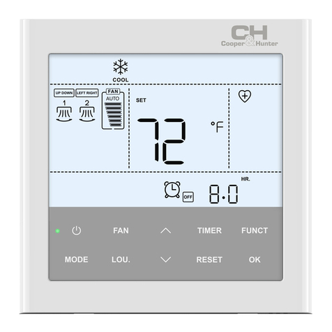
Timberk TMS 08.CH User manual

Instruction manual
Outlook of devices, aslo colour scores can be revised without any special advance notices.
Remote control block
ÀÂ71

Dear Customer!
Thank you for your good choice and purchase of a remote control unit for a Timberk infrared
heater. It will serve you long
TMS 08.CH model remote control unit is designed to control TCH A1N, TCH A2 infrared
heater.
1. IMPORTANT INFORMATION
Please, read this operation manual carefully prior to using and connecting the remote con-
trol unit to an infrared heater.
This operation manual contains important information regarding your safety, as well as rec-
ommendations on the proper operation of the unit and its maintenance.
Keep this operation manual for further use. The purchased remote control can slightly dier
from the one, described in the manual, but that doesn't aect methods of its use and opera-
tion.
Important precautions and instructions, contained in this manual, do not account for all pos-
sible modes and situations to be encountered. It is vital to understand that common sense,
caution and thoroughness are the factors that are impossible to be built-in in any product.
These factors must be taken into consideration by a person, interested in proper operation
of the unit. The manufacturer does not bear any responsibility in case when the unit or its
parts are damaged during transportation, as a result of improper installation, voltage uctua-
tions, as well as if some part of the unit was altered or modied.
2www.timberk.com remote control block

2. PRECAUTIONS
A number of precautions is to be observed upon operation of an infrared heater and a remote control
unit. Improper operation as a result of ignoring precautions may harm health of the user and other
people, as well as damage their property.Detailed description of precautions is given in the infrared
heater's operation manual.
3. PURPOSE
The remote control unit allows to switch an infrared heater on/o, select power (except TCH A2) and set a
switch o timer for a heater from a remote control.
4. TECHNICAL CHARACTERISTICS
Technical characteristics of the remote control unit are given in Table 1 below.
Voltage
Frequency
Power consumption
Maximum load power
Remote control operating range
Electrical protection class
Moisture protection class
Overall dimensions
Weight
V
Hz
W
W
m
-
-
mm
kg
220/380
50
0,6
3000
5
II
IP20
3813590
0,26
Table 1
Description Units Product identification number
TMS 08.CH
3www.timberk.com remote control block
The manufacturer reserves the right to change the set-list of the device (including liquid and powder components) for different supplies
without prior notice. The changes either in no way influence the basic technical parameters of the device or may improve them, and also
not violate the legislation or quality standards of the countries of manufacture, transit and selling.
The changes in the set-list may result in changing of the weight and dimensions of the device, but not more than by +\- 5-20% (depending
on the product category)

For a more detailed description of technical parameters and characteristics go to
www.timberk.ru or ask TIMBERK ocial dealers.
5. DIMENSIONAL FEATURES
Overall dimensions of the remote control unit in mm are given in Fig.1.
Fig. 1
4www.timberk.com remote control block
135
38

ENGLISH
6. Description of the remote control unit
The remote control unit consists of a control unit and a remote controller.
Control unit (Fig. 2)
1
2
3
4
1. POWER indicator
2. IR-signal receiver
3. Heat indicators
4. Timer indicators
Fig. 2
5www.timberk.com remote control block

Remote controller (g. 3)
The remote controller should be directed to the signal receiver, located on the control unit.
The control unit conrms receipt of a control command by a sound signal.
Mounting of batteries
The remote controller is power supplied from two AAA batteries (not included in the scope
of delivery), installed in a special compartment whose cover is located on the back panel of
the remote controller. To mount batteries:
1. Remove the cover of the battery compartment by sliding it along the direction of the
arrow.
2. Mount batteries, observing specied polarity.
3. Place the cover back.
IMPORTANT!
1. Prevent contact of the remote controller with water and other liquids. Prevent
contact of the remote controller with direct sunlight and do not leave it nearby
heaters and electric appliances.
2. Prevent contact of direct sunlight with the infrared signal receiver.
8
6www.timberk.com remote control block

ENGLISH
1. LCD-display
Timer's time value and symbols of unit operation and
functions are shown on the display.
2. « » Button
It is used to increase the selected value.
3. « » Button
It is used to activate timer.
4. « » Button
It is used to decrease the selected value.
5. ON/OFF button
It is used to switch an infrared heater on and o.
6. MODE button
It is used to program modes in accordance with the infrared
heater model.
7. HEAT button
It is used to select heating power modes (except TCH A2).
Fig. 3
7www.timberk.com remote control block
1
5
2
7
6
4
3

7. SCOPE OF DELIVERY
1. Control unit 1 pc.
2. Remote controller 1 pc.
3. Operation manual and guarantee card 1 pc.
4. Packing 1 pc.
NOTE:
To improve the product quality, design and technical characteristics of the remote control
unit as well as its complete set may be changed by the manufacturer without any prior
notice.
8. CONNECTION
1. Prior to connecting the control unit to the electric mains, make sure that parameters of
the electric mains in the place of connection comply with parameters, specied on the
marking plate with unit's technical data.
2. Work to connect the unit to the electric mains must be performed only by qualied
specialists in accordance with the set Electric Installation Code and Safety Rules for
Operation of Electrical Installations Operating at Voltage Up to 1000V.
IMPORTANT!
All work to connect the control unit to an infrared heater must be performed only
after it is completely de-energized.
8www.timberk.com remote control block

ENGLISH
Connecting to TCH A1N infrared heater
1. Infrared heater and control unit are designed to connect to the AC mains with 220V single-
phase voltage (allowable voltage uctuations from 198V to 242V).
2. To connect the control unit to the electric mains and a heater, unscrew 2 screws behind the
unit and remove the top cover.
3. The control unit is connected in compliance with the diagram, specied in Fig. 4, on the
case of an infrared heater and terminal block of the control unit.
4. The unit must be connected to the electric mains by the cable with strand cross section
not less than 1.5 mm2 and along with installation in the electric mains of a circuit breaker
with rated current not less than 16A.
5. After the unit is connected, switch 2 on the control unit must be switched ON (see Fig. 4),
place the top cover of the control unit back and secure the unit on an infrared heater.
9www.timberk.com remote control block

Connecting to TCH A2 infrared heater
1. Infrared heater and control unit are designed to connect to the AC mains with 220V
single-phase voltage (allowable voltage uctuations from 198V to 242V).
2. To connect the control unit to the electric mains and a heater, unscrew 2 screws behind
the unit and remove the top cover.
3. The control unit is connected in compliance with the diagram, specied in Fig. 5, on the
case of an infrared heater and terminal block of the control unit.
4. The unit must be connected to the electric mains by the cable with strand cross section
not less than 1.5 mm2 and along with installation in the electric mains of a circuit breaker
with rated current not less than 16A.
Fig. 4
10 www.timberk.com remote control block
700W/1000W/
1500W/2000W
Heating element
Heating element
N
L2
PE
L
L1
N
R1
OUT
IN
R2
R3
L3
L2
L1
N
Relay
K
Relay
K
N
220V~
NO
1 2

ENGLISH
5. After the unit is connected, switch 1 on the control unit must be switched ON (see Fig. 5),
place the top cover of the control unit back and secure the unit on an infrared heater.
Fig. 5
11www.timberk.com remote control block
800W/1000W
Heating element
N
PE
L
N
N
R1
OUT
IN
R2
R3
L3
L2
L1
N
Relay
K
N
220V~
NO
1 2

9. OPERATING AN INFRARED HEATER BY THE REMOTE CONTROL UNIT (g. 2, g.3)
1. Programming
Prior to the rst use of an infrared heater by the remote control unit or replacement of
batteries in the remote controller, it should be programmed in accordance with the heater
model, to do this:
- connect the infrared heater to a power supply unit,
- press ON/OFF button, mode 1 symbol and « » symbol will start blinking on the remote
controller's display, and POWER indicator will ash on the control unit.
- press « » or « » button within 10 seconds to select mode 1 (for TCH A2) or mode 2
(for TCH A1N) according to the heater model.
- to nish the selection, press MODE and hold it for 5 seconds, the MODE number symbol
stop blinking and the symbol LOCK will display on the LCD. Only nished this process, the
setting of HEAT and TIMER could be carried out.
NOTE:
If the mode is selected incorrectly, the control unit will make a triple sound signal. In this
case the mode must be reselected according to the heater model, to do this press MODE
button and hold it for 5 seconds, then repeat the above actions.
12 www.timberk.com remote control block

ENGLISH
2. Switching on
Press ON/OFF button, symbols will be shown on the remote controller's display and POWER
indicator will ash on the control unit.
3. Setting a heating power mode
3.1. For TCH A2 infrared heater
3.1.1. Press HEAT button
3.1.2. To conrm the selection, press HEAT button again in 5 seconds after press HEAT
button, then a sound signal will be made, heating will be switched on, and heating
indicators will ash on the control unit.
3.2. For TCH A1N infrared heater
3.2.1. Press HEAT button, at that « » symbol will ash on the remote controller and start
blinking.
3.2.2. Press « » or « » button to select the high power mode ( « »symbol) or low
power mode ( « »symbol).
3.2.3. To conrm the selection, press HEAT button again in 5 seconds after press HEAT
button, then a sound signal will be made, heating will be switched on, and heating
indicators will ash on the control unit.
4. Setting timer functions to switch o the heater
4.1. When the heater operates in the heating mode, press « » button, then [00] value will
be shown on the display and start blinking.
4.2. Press « » or « » button to set the heater switch o time, with 1 hour increment, 0 to
13 hours. The display will show the countdown of time, remaining till the heater is switched
o.
13www.timberk.com remote control block

4.3. To conrm the selection, press « » button in 5 seconds after adjust time, then a sound
signal will be made and timer will be activated, and the respective timer indicators will ash
on the control unit.
4.4. To deactivate timer, press « » button and hold it for 5 seconds.
5. Switching o
Press ON/OFF button, and indicators on the remote controller's display and indicators on
the control unit will go down.
10. DISPOSAL
The water heater should be disposed upon the end of life in compliance with codes, rules
and methods in use at the disposal site. You can obtain detailed information on the remote
control unit disposal from a representative of local authorities.
14 www.timberk.com remote control block

TMS 08.CH
TCH A1N, TCH A2
!
Timberk. .
1.
-
.
,
,
.
.
, -
.
, ,
, .
, ,
, «» .
,
15www.timberk.com

. -
,
, , ,
- .
2.
-
, .
, .-
.
3.
/
, ( TCH A2)
().
4.
1.
16 www.timberk.com

-
-
220/380
50
0,6
3000
5
II
IP20
3813590
0,26
1.
E. . TMS 08.CH
www.timberk.com TIMBERK
5.
. 1
17www.timberk.com
( \
),
, \
\ .
, +\- 5-20%
( ).

Рис. 1
18 www.timberk.com
38
135

6. .
( ).
(. 2)
1
2
3
. 2
1. «POWER» - /
2. -
3.
4.
4
19www.timberk.com

()(. 3)
,
.
.
!
1. .
.
2.
.
(
), , -
. :
1. ,
.
2. , .
3. .
20 www.timberk.com
Table of contents
Popular Remote Control manuals by other brands
wattstopper
wattstopper Legrand Miro Key Fob installation instructions
One Forall
One Forall URC-9900 Frequently asked questions
Contro l4
Contro l4 SR-250 Setup guide
CO/Tech
CO/Tech 50051 quick start guide
GiBiDi
GiBiDi MAKO AU03200 quick start guide

Shuangri Electron
Shuangri Electron SR258 Operation manual
