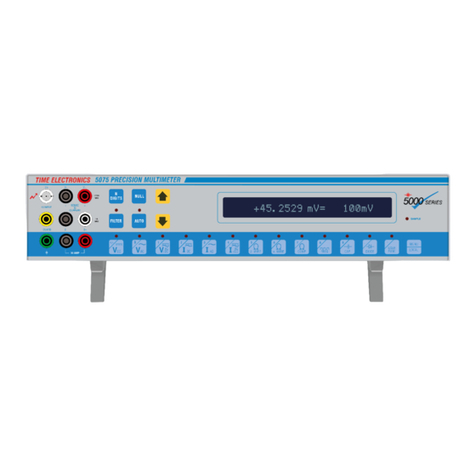
Time Electronics 5075 Use and care manual

Time Electronics Ltd
BOTANY INDUSTRIAL ESTATE
TONBRIDGE, KENT, TN9 1RH, UK
Tel: 01732 355993 Fax: 01732 770312
Email: mail@TimeElectronics.co.uk
Website: www.TimeElectronics.co.uk
5075
Precision
Digital Multimeter
Calibration Manual
V17 16/11/06

5075 Calibration Manual Page 2
Contents
Page
1. General Calibration Information 4
1.1 List of required equipment for calibration 4
1.2 Before and after calibration 4
1.3 Calibration factors 5
1.4 Calibration Precautions 5
Calibration leads and connections 5 - 6
Othererrors 6
Safety 7
2. Calibration Procedure 7
2.1 Calibration key 7
2.2 GPIB(IEEE) Address 7
2.3INTCAL 7
2.3 Menu options 8 - 9
2.4 5075 push buttons 9
2.5 Calibration Initialize 10
2.6 Calibration of DC Volt Ranges 11
Set Zero - Low DC Volt ranges 11
Set Full-Scale - Low DC Volt ranges 11 - 13
Set Zero - High DC Volt ranges 13
Set Full-Scale - High DC Volt ranges 13 - 14
Set Zero - Extra high DC Volt ranges 14
Set Full-Scale - Extra high DC Volt ranges 14 - 15
2.7 Calibration of DC Current Ranges 16
Set Zero - DC Current ranges 16 - 17
Set Full-Scale - DC Current ranges to 1 amp 17 - 19
Set Full-Scale - DC high Current ranges 20
2.8 Calibration of AC Voltage Ranges 21
Set Full Scale - AC Volt range 21 - 22
Set Full Scale - Extra high AC Volt range 22
2.9 Calibration of AC Current Ranges 23
Set Full-Scale - Low AC Current ranges 60Hz 23
Set Full-Scale - High AC Current ranges 60Hz 24
3.0 Calibration of Capacitance 25
Set ‘Zero’ Capacitance 25
Set Full Scale Capacitance 25 - 26
3.1 Calibration of Resistance 27
Set Zero calibration factors 27 - 29
Set Full Scale Resistance 30 - 33

5075 Calibration Manual Page 3
Contents continued
Page
3.2 Calibration Data Entry 34
Certification Number entry 34
Calibration Date entry 34
Calibration Temperature entry 35
Calibration Due Date entry 35
Calibration Period entry 35
Sample Certificate of Calibration 36 - 40

5075 Calibration Manual Page 4
1. General Calibration Information
1.1 Calibration equipment required :
• Precision multifunction calibrator e.g. Time 5025
• Precision multimeter e.g. HP 3458A
• Precision multi-resistor standard box e.g. Time 7003 (1to 10M)
• 10m4 wire standard
• 100m4wire standard
• 100M2wire standard
• 1000M2 wire standard
• 30nF capacitance standard
• 300nF capacitance standard
• 3µF capacitance standard
• 30µF capacitance standard
• 300µF capacitance standard
• Precision low noise DC current source 3µA, 30µA, 100µA e.g. Time 1024
• Screened low thermal e.m.f. 4 wire test leads
• Screened low thermal e.m.f. 2 wire test leads
• High current (32amp) test leads
• BNC high voltage, 10kV test leads
• Supplied calibration key
• Technical manual
Switch on the 5075, the multifunction calibrator and the low noise DC current source
and leave them on to warm up for at least 2 hours prior to calibration, ambient room
temperature for calibration should be 22oC ± 2oC
1.2 Before and After calibration
It is advisable that a complete set of calibration results are taken before the re-
calibration is started in ordinary mode i.e. IEEE address not 0,16 or 32. This process
is know as the ‘BEFORE’. It is important because it verifies that the 5075 is
operating correctly on all ranges and indicates which ranges will need adjustment. If
any of the ranges are a long way out it indicates that the 5075 might be faulty.
Please refer to the Time Electronics example calibration certificate at the end of this
document, for details of the allowed errors of the calibration adjustment points.
Please note that some of the allowed errors shown may be slightly more precise
than the published specification.

5075 Calibration Manual Page 5
1.3 Calibration Factors
The calibration factors are numerical values stored in internal non-volatile memory.
When calibration is complete, it is good practice to keep a written record of all the
calibration factors for future reference. Should the 5075 lose its internal memory or the
calibration factors become corrupted for any reason, it will be possible to re-enter them
without having to go to length of a full re-calibration. It should be noted that the zero
calibration factors are not available for inspection and therefore can not be recorded.
However, it is not difficult to re-calibrate each range zero with a shorting link (or open
circuit for current and capacitance ranges).
1.4 Calibration Precautions
Before calibrating the 5075 instrument, please read though this manual and ensure that
you learn all of the following points :
Range specific information
Normally the 5075 is not adjusted for calibration within the following functions,
Volts (AC+DC) mixed signal
Current (AC+DC) mixed signal
PRT option
Frequency
Ohms compensated
Hence on these ranges during calibration procedure of the 5075 they should be tested
and recorded on the calibration certificate, however there is no adjustment. If a 5075
unit seems to be out of specification on these ranges then contact Time Electronics for
advice.
Additionally it is acceptable for the 3kV and 10kV ranges to be calibrated only with a
precision 1kV voltage source.
All AC voltage ranges are to be calibrated at 200Hz
All AC current ranges are to be calibrated at 60Hz
Calibration leads and connections
Thermal EMF’s can affect calibration. The terminals of the 5075 are made from linear
crystal oxygen free copper to minimize this effect. If however nickel plated brass plugs
are used, thermally generated emfs will be generated and errors will occur. Leads and
connectors that exhibit low self thermal emf effect should be used especially on voltage
ranges below 10V.
To further reduce noise and AC capacitive/inductive coupling, the leads should be kept
as short as practically possible. The use of short screened leads is recommended for all
low AC voltage and current calibrations.

5075 Calibration Manual Page 6
Calibration leads and connections (continued)
For calibration of the 3kV and 10kV ranges, use the BNC input connector. The
shield of the BNC cable is earth, as with the supplied HV cable a short flying lead
connects the shield to the negative sense input socket.
Resistance calibration up to the 300krange must be calibrated using a 4-wire type
source, ranges above this should be calibrated using a 2-wire type resistance.
When calibrating resistance ranges of 1Mand above, screened (shielded) leads
must be used to reduce noise. The shield should be connected to the yellow guard
terminal. If difficalties are being experianced and readings are unstable or not
repeatable, please read the ‘Measurement Techniques’ chapter in the 5075
technical manual carefully.
Other errors
When switching from a range greater than 10V down to mV ranges, additional time
must be allowed for zero settling, around 90 seconds.
Whilst calibrating the 10 Amp and 30 Amp ranges, do not leave the current on for
longer then required to take a reading as self heating via the internal current shunts
will cause thermal drift.
Avoid open circuiting the input terminals on the 3 Ohm or the 30 Ohm resistance
ranges since the zero settling effect will cause errors.
Safety
EXTREME CAUTION must be exercised when calibrating very high voltages or high
currents. When working with high voltage do not work alone and do not depend
upon the insulation of the cables for protection. When in doubt please refer to the
5075 technical manual for information on connection.

5075 Calibration Manual Page 7
2. Calibration Procedure
IMPORTANT NOTE: If the 5075 has corrupted Cal Factors (Cal Factor Error 002) it is
necessary to clear the Cal factors before re-calibration as follows.
1) Switch off 5075
2) Select address 32 on GPIB address dip switch (all switches ON - down)
3) Insert Cal Key
4) Switch on 5075
5) You will see the 5075 run through a self test and when finished show ‘PASS’
6) Switch off the 5075
The 5075 is now ready to be re-calibrated as described below.
2.1 Calibration key
The 5075 has a separate calibration key (referred to as Cal Key). It is plugged in a
rear panel socket (near the GPIB switch). The calibration factors in the 5075 can not
be modified or deleted without this key inserted. When the cal key is inserted a small
‘c’ appears on the display next to the units - the cal factors can now be changed.
2.2 GPIB(IEEE) Address
The GPIB address is changed via the dip switches at the back.
The following address are used for special purposes,
2.3 INTCAL
If INTCAL appears on the screen while calibrating the 5075, wait for it to finish, and
then repeat only the calibration of the range currently selected.
INTCAL is an internally generated self-calibration function which automatically occurs
approximately every 15 minutes. It does not affect the external calibration.
0 and 16 Set 5075 in to calibration mode, enhanced menu access
32 Initialize a full reset and internal test for all functions of the 5075. If
cal key is in, this function will also clear all cal factors stored in the
5075’s memory and it will have to be re-calibrated.

5075 Calibration Manual Page 8
2.3 Menu options
The 5075 menu is entered by using the ‘MENU’ key, it can be navigated through the
options by using the ’UP’ and ‘DOWN’ arrow keys, and selection is then confirmed
using the ‘USER FUNC’ key, also referred to as the ‘E’ key.
When the 5075’s IEEE address is set to ether 0 or 16, the menu has expanded
selections to include the calibrate mode options. Even though the menu will display
options to adjust the calibration factors, they cannot be selected unless the cal key
is in place on the rear of the machine. Step through the options and check they are
correct before commencing calibration.

5075 Calibration Manual Page 9
2.3 Menu options (continued)
Please note that the Cal key does not have to be inserted to view all
options, but it MUST be inserted to edit or execute functions marked
with ‘*’
2.4 5075 push buttons
In this manual the 5075 push buttons will be referred to as the legends as printed on
them, e.g ‘MENU’. However throughout this document we will use the shorthand for
the ‘User Func’ key which is written as ‘E’ this is used to select items from the menu.
A. Self Test & Reset Run this to internally test all of the 5075 functions
B. IEEE Address Indicates the setting of the rear panel switches
C. Serial Number* Display and change the 7075 serial number
D. Certificate Number* Previous cert. Number. To be updated after calibration
E. Calibration Date* Previous cal date. To be updated after calibration
F. Calibration Due* Previous cal due date. If run out, set before cal run
G. Calibration Temperature* Ambient room temperature at time of calibration
H. Calibration Period* Normally 52 weeks, can be set from 1 to 999 weeks
I. Key press beep on/off Select as required
J. Continuity beep on/off Select as required
K. Sample beep on/off Select as required. Turn OFF for calibration run
L. Analogue filter on/off Select as required. Turn ON for calibration
M. Countdown on/off Select as required. Used with the dynamic I/O filter
N. Scanner display on/off Select if scanner fitted. OFF for calibration
O. Auto Dynamic filter on/off Select as required. Turn ON for calibration
P. PRT Temperature Select as required. Turn OFF for calibration
Q. Calibration due warning Select as required. Indicates when overdue for calibration
R. Store options* Stores options/front panel settings as power up defaults
S. Date Shows current date
T. Time Shows current time
U. Internal Temperature Shows 5075 internal temperature for reference only
V. Self Calibrate Initiates a ‘INTCAL’. Always do this before a calibration run
W. Clear Cal Factors on/off* Clears the cal factors for the selected range. LEAVE OFF
X. Display Cal Factors on/off Shows the cal factors for the current range. Replaces range info.
Y. Adjust to Value* Used to set the cal factor for non full scale inputs
Z. Calibrate to full scale* Used to set the cal factor with full scale input

5075 Calibration Manual Page 10
2.5 Calibration Initialize
• Make a note of original IEEE switch setting.
• Change IEEE address of the 5075 to 16 ( refer to page 39 of 5075 tech
manual) to enter calibration mode.
• Power-up the 5075 and go into the menu by pressing ‘Menu’ then select the
option “Self Test & Reset” to check if the 5075 functions are operating
correctly.
• Power-up all calibration equipment and allow 2 hours for all equipment
including the 5075 to warm up and stabilize.
• Press the ‘Filter’ button repeatedly until a filter time of 1 second is selected.
• Press the ‘N Digits’ button repeatedly until a 6 digit display is selected.
• Press the ‘Auto’ button to turn OFF auto range.
• Enter the options menu by pressing ‘Menu’ and change the following options :
Sample beep on/off Set to OFF
Analogue filter on/off Set to ON
Scanner display on/off` Set to OFF
Auto dynamic filter on/off Set to ON
PRT Temperature on/off Set to OFF
• Enter the options menu by pressing ‘Menu’ and using the ‘Ï’ and ‘Ð’ arrow
keys, select “Self Calibration” and confirm by pressing the ‘E’ key. This calls a
INTCAL and sets the internal A-to-D converter before calibration.

5075 Calibration Manual Page 11
2.6 Calibration of DC Volt Ranges
• Press ‘Vdc’ to enter DC volts function.
• Set the address switch, see section 2.2.
• Insert the Cal key, a small ‘c’ will appear on the display.
• It is important that the filter is set as described in section 2.5.
Set Zero - Low DC Volt ranges
• Short-circuit the voltage input terminals using a solid link or the low thermal
test leads to ensure that terminals are at zero volts.
• When adjusting the low voltage zero’s leave about 30seconds for DVM to
settle before pressing ’CAL NULL’ button.
• Change range using the ‘Ï’ and ‘Ð’ arrow keys, select 10V range.
• Press the ‘Null’ key to zero the reading. The ‘Null’ key may need pressing
several times.
• Change range using the ‘Ï’ and ‘Ð’ arrow keys, select 3V range.
• Press the ‘Null’ key to zero the reading. The ‘Null’ key may need pressing
several times.
• Change range using the ‘Ï’ and ‘Ð’ arrow keys, select 1V range.
• Press the ‘Null’ key to zero the reading. The ‘Null’ key may need pressing
several times.
• Change range using the ‘Ï’ and ‘Ð’ arrow keys, select 300mV range.
• Press the ‘Null’ key to zero the reading. The ‘Null’ key may need pressing
several times.
• Change range using the ‘Ï’ and ‘Ð’ arrow keys, select 100mV range.
• Press the ‘Null’ key to zero the reading. The ‘Null’ key may need pressing
several times.
• Change range using the ‘Ï’ and ‘Ð’ arrow keys, select 30mV range.
• Press the ‘Null’ key to zero the reading. The ‘Null’ key may need pressing
several times.
• Change range using the ‘Ï’ and ‘Ð’ arrow keys, select 10mV range.
• Press the ‘Null’ key to zero the reading. The ‘Null’ key may need pressing
several times.
• Change range using the ‘Ï’ and ‘Ð’ arrow keys, select 3mV range.
• Press the ‘Null’ key to zero the reading. The ‘Null’ key may need pressing
several times.
Set Full-Scale - Low DC Volt ranges.
• Change range using the ‘Ï’ and ‘Ð’ arrow keys, select 10V range.
• Apply +10V full scale voltage to the input sense terminals.
• Enter the ‘Menu’ and navigate to find “Cal to full scale” press ‘E’ to set the
positive full scale calibration factor.
• Apply -10V full scale voltage to the input sense terminals.
• Enter the ‘Menu’ and navigate to find “Cal to full scale” press ‘E’ to set the
negative full scale calibration factor.

5075 Calibration Manual Page 12
Set Full-Scale - Low DC Volt ranges (continued)
• Change range using the ‘Ï’ and ‘Ð’ arrow keys, select 3V range.
• Apply +3V full scale voltage to the input sense terminals.
• Enter the ‘Menu’ and navigate to find “Cal to full scale” press ‘E’ to set the
positive full scale calibration factor.
• Apply -3V full scale voltage to the input sense terminals.
• Enter the ‘Menu’ and navigate to find “Cal to full scale” press ‘E’ to set the
negative full scale calibration factor.
• Change range using the ‘Ï’ and ‘Ð’ arrow keys, select 1V range.
• Apply +1V full scale voltage to the input sense terminals.
• Enter the ‘Menu’ and navigate to find “Cal to full scale” press ‘E’ to set the
positive full scale calibration factor.
• Apply -1V full scale voltage to the input sense terminals.
• Enter the ‘Menu’ and navigate to find “Cal to full scale” press ‘E’ to set the
negative full scale calibration factor.
• Change range using the ‘Ï’ and ‘Ð’ arrow keys, select 300mV range.
• Apply +300mV full scale voltage to the input sense terminals.
• Enter the ‘Menu’ and navigate to find “Cal to full scale” press ‘E’ to set the
positive full scale calibration factor.
• Apply -300mV full scale voltage to the input sense terminals.
• Enter the ‘Menu’ and navigate to find “Cal to full scale” press ‘E’ to set the
negative full scale calibration factor.
• Change range using the ‘Ï’ and ‘Ð’ arrow keys, select 100mV range.
• Apply +100mV full scale voltage to the input sense terminals.
• Enter the ‘Menu’ and navigate to find “Cal to full scale” press ‘E’ to set the
positive full scale calibration factor.
• Apply -100mV full scale voltage to the input sense terminals.
• Enter the ‘Menu’ and navigate to find “Cal to full scale” press ‘E’ to set the
negative full scale calibration factor.
• Change range using the ‘Ï’ and ‘Ð’ arrow keys, select 30mV range.
• Apply +30mV full scale voltage to the input sense terminals.
• Enter the ‘Menu’ and navigate to find “Cal to full scale” press ‘E’ to set the
positive full scale calibration factor.
• Apply -30mV full scale voltage to the input sense terminals.
• Enter the ‘Menu’ and navigate to find “Cal to full scale” press ‘E’ to set the
negative full scale calibration factor.
• Change range using the ‘Ï’ and ‘Ð’ arrow keys, select 10mV range.
• Apply +10mV full scale voltage to the input sense terminals.
• Enter the ‘Menu’ and navigate to find “Cal to full scale” press ‘E’ to set the
positive full scale calibration factor.
• Apply -10mV full scale voltage to the input sense terminals.
• Enter the ‘Menu’ and navigate to find “Cal to full scale” press ‘E’ to set the
negative full scale calibration factor.
• Change range using the ‘Ï’ and ‘Ð’ arrow keys, select 3mV range.
• Apply +3mV full scale voltage to the input sense terminals.
• Enter the ‘Menu’ and navigate to find “Cal to full scale” press ‘E’ to set the
positive full scale calibration factor.

5075 Calibration Manual Page 13
Set Full-Scale - Low DC Volt ranges (continued)
• Apply -3mV full scale voltage to the input sense terminals.
• Enter the ‘Menu’ and navigate to find “Cal to full scale” press ‘E’ to set the
negative full scale calibration factor.
Set Zero - High DC Volt ranges
• Short-circuit the voltage sense input terminals using a solid link to ensure that
terminals are at zero volts.
• Change range using the ‘Ï’ and ‘Ð’ arrow keys, select 1kV range.
• Press the ‘Null’ key to zero the reading. The ‘Null’ key may need pressing
several times.
• Change range using the ‘Ï’ and ‘Ð’ arrow keys, select 300V range.
• Press the ‘Null’ key to zero the reading. The ‘Null’ key may need pressing
several times.
• Change range using the ‘Ï’ and ‘Ð’ arrow keys, select 100V range.
• Press the ‘Null’ key to zero the reading. The ‘Null’ key may need pressing
several times.
• Change range using the ‘Ï’ and ‘Ð’ arrow keys, select 30V range.
• Press the ‘Null’ key to zero the reading. The ‘Null’ key may need pressing
several times.
Set Full-Scale - High DC Volt ranges
• Change range using the ‘Ï’ and ‘Ð’ arrow keys, select 1kV range.
• Apply +1kV full scale voltage to the input sense terminals.
• Enter the ‘Menu’ and navigate to find “Cal to full scale” press ‘E’ to set the
positive full scale calibration factor.
• Apply -1kV full scale voltage to the input sense terminals.
• Enter the ‘Menu’ and navigate to find “Cal to full scale” press ‘E’ to set the
negative full scale calibration factor.
• Change range using the ‘Ï’ and ‘Ð’ arrow keys, select 300V range.
• Apply +300V full scale voltage to the input sense terminals.
• Enter the ‘Menu’ and navigate to find “Cal to full scale” press ‘E’ to set the
positive full scale calibration factor.
• Apply -300V full scale voltage to the input sense terminals.
• Enter the ‘Menu’ and navigate to find “Cal to full scale” press ‘E’ to set the
negative full scale calibration factor.
• Change range using the ‘Ï’ and ‘Ð’ arrow keys, select 100V range.
• Apply +100V full scale voltage to the input sense terminals.
• Enter the ‘Menu’ and navigate to find “Cal to full scale” press ‘E’ to set the
positive full scale calibration factor.
• Apply -100V full scale voltage to the input sense terminals.
• Enter the ‘Menu’ and navigate to find “Cal to full scale” press ‘E’ to set the
negative full scale calibration factor.

5075 Calibration Manual Page 14
Set Full-Scale - High DC Volt ranges (continued)
• Change range using the ‘Ï’ and ‘Ð’ arrow keys, select 30V range.
• Apply +30V full scale voltage to the input sense terminals.
• Enter the ‘Menu’ and navigate to find “Cal to full scale” press ‘E’ to set the
positive full scale calibration factor.
• Apply -30V full scale voltage to the input sense terminals.
• Enter the ‘Menu’ and navigate to find “Cal to full scale” press ‘E’ to set the
negative full scale calibration factor.
Set Zero - Extra high DC Volt ranges
• Short-circuit the EHT sense using a low resistance link. This link will connect
from the center of the BNC connector to the -ve voltage sense terminal.
• Change range using the ‘Ï’ and ‘Ð’ arrow keys, select 10kV range.
• Press the ‘Null’ key to zero the reading. The ‘Null’ key may need pressing
several times.
• Change range using the ‘Ï’ and ‘Ð’ arrow keys, select 3kV range.
• Press the ‘Null’ key to zero the reading. The ‘Null’ key may need pressing
several times.
Set Full-Scale - Extra high DC Volt ranges
For calibration of the 3kV and 10kV ranges, use the BNC input connector. The
shield of the BNC cable is earth, as with the supplied HV cable a short flying lead
connects the shield to the negative sense input socket.
Refer to 5075 technical manual for connection advice on using the BNC input.
• Change range using the ‘Ï’ and ‘Ð’ arrow keys, select 3kV range.
• Apply +3kV full scale voltage to the input sense terminals.
• Enter the ‘Menu’ and navigate to find “Cal to full scale” press ‘E’ to set the
positive full scale calibration factor.
• Apply -3kV full scale voltage to the input sense terminals.
• Enter the ‘Menu’ and navigate to find “Cal to full scale” press ‘E’ to set the
negative full scale calibration factor.
• Change range using the ‘Ï’ and ‘Ð’ arrow keys, select 10kV range.
• Apply +10kV full scale voltage to the input sense terminals.
• Enter the ‘Menu’ and navigate to find “Cal to full scale” press ‘E’ to set the
positive full scale calibration factor.
• Apply –10kV full scale voltage to the input sense terminals.
• Enter the ‘Menu’ and navigate to find “Cal to full scale” press ‘E’ to set the
negative full scale calibration factor.

5075 Calibration Manual Page 15
DC Volt ranges complete
• Remove calibration key.
• Set address switch back to your normal address when calibration is complete.
‘Ï’ Increase displayed value by 1ppm
‘Null’ Increase displayed value by 10ppm
‘N Digits’ Increase displayed value by 100ppm
‘Ð’ Decrease displayed value by 1ppm
‘Auto’ Decrease displayed value by 10ppm
‘Filter’ Decrease displayed value by 100ppm
Set Full-Scale - Extra high DC Volt ranges (continued)
If a multifunction calibrator is not available which is capable of producing a 10kV and
3kV signal to calibrate the full scale of the 5075. A calibrator that can produce a
accurate 1kV signal can be used. Hence a different process in this situation would
need to be used to calibrate the 10kV and 3kV ranges.
The following procedure must be used in this situation:
• Change range using the ‘Ï’ and ‘Ð’ arrow keys, select 3kV range.
• Apply +1kV full scale voltage to the BNC input. Refer to 5075 technical manual
for connection advice on using the BNC input. Enter the ‘Menu’ and using the
‘Ï’and ‘Ð’ arrow keys navigate to find ‘Adjust to value’, Press the ’E’ key
again.
• The small ‘c’ on the display will now change to a large ‘C’.
• Using the keys in table 1 Page 14, adjust the display to read that of the input
voltage. Press the ’E’ key again to store the calibration factor.
• Change range using the ‘Ï’ and ‘Ð’ arrow keys, select 10kV range.
• Apply +1kV full scale voltage to the BNC input. Refer to 5075 technical manual
for connection advice on using the BNC input. Enter the ‘Menu’ and using the
‘Ï’ and ‘Ð’ arrow keys navigate to find ‘Adjust to value’, Press the ’E’ key
again.
• The small ‘c’ on the display will now change to a large ‘C’.
• Using the keys in table 1 Page 14, adjust the display to read that of the input
voltage. Press the ’E’ key again to store the calibration factor.
Table 1.

5075 Calibration Manual Page 16
2.7 Calibration of DC Current Ranges
• Press ‘Idc’ to enter DC current function.
• Press ‘Auto’ until the auto range facility is turned off.
• Set the address switch, see section 2.2.
• Insert the Cal key, see section 2.1.
Set Zero - DC Current ranges
• To zero current ranges the terminals MUST be left open circuit with out any
leads attached to guarantee a zero current flow.
• Change range using the ‘Ï’ and ‘Ð’ arrow keys, select 30A range.
• Press the ‘Null’ key to zero the reading. The ‘Null’ key may need pressing
several times.
• Change range using the ‘Ï’ and ‘Ð’ arrow keys, select 10A range.
• Press the ‘Null’ key to zero the reading. The ‘Null’ key may need pressing
several times.
• Change range using the ‘Ï’ and ‘Ð’ arrow keys, select 3A range.
• Press the ‘Null’ key to zero the reading. The ‘Null’ key may need pressing
several times.
• Change range using the ‘Ï’ and ‘Ð’ arrow keys, select 1A range.
• Press the ‘Null’ key to zero the reading. The ‘Null’ key may need pressing
several times.
• Change range using the ‘Ï’ and ‘Ð’ arrow keys, select 300mA range.
• Press the ‘Null’ key to zero the reading. The ‘Null’ key may need pressing
several times.
• Change range using the ‘Ï’ and ‘Ð’ arrow keys, select 100mA range.
• Press the ‘Null’ key to zero the reading. The ‘Null’ key may need pressing
several times.
• Change range using the ‘Ï’ and ‘Ð’ arrow keys, select 30mA range.
• Press the ‘Null’ key to zero the reading. The ‘Null’ key may need pressing
several times.
• Change range using the ‘Ï’ and ‘Ð’ arrow keys, select 10mA range.
• Press the ‘Null’ key to zero the reading. The ‘Null’ key may need pressing
several times.
• Change range using the ‘Ï’ and ‘Ð’ arrow keys, select 3mA range.
• Press the ‘Null’ key to zero the reading. The ‘Null’ key may need pressing
several times.
• Change range using the ‘Ï’ and ‘Ð’ arrow keys, select 1mA range.
• Press the ‘Null’ key to zero the reading. The ‘Null’ key may need pressing
several times.
• Change range using the ‘Ï’ and ‘Ð’ arrow keys, select 300uA range.
• Press the ‘Null’ key to zero the reading. The ‘Null’ key may need pressing
several times .
• Change range using the ‘Ï’ and ‘Ð’ arrow keys, select 100uA range.

5075 Calibration Manual Page 17
Set Zero - DC Current ranges (continued)
• Press the ‘Null’ key to zero the reading. The ‘Null’ key may need pressing
several times.
• Change range using the ‘Ï’ and ‘Ð’ arrow keys, select 30uA range.
• Press the ‘Null’ key to zero the reading. The ‘Null’ key may need pressing
several times .
• Change range using the ‘Ï’ and ‘Ð’ arrow keys, select 10uA range.
• Press the ‘Null’ key to zero the reading. The ‘Null’ key may need pressing
several times.
• Change range using the ‘Ï’ and ‘Ð’ arrow keys, select 3uA range.
• Press the ‘Null’ key to zero the reading. The ‘Null’ key may need pressing
several times.
Set Full-Scale - DC Current ranges to 1 amp (use 1 amp terminals)
• Change range using the ‘Ï’ and ‘Ð’ arrow keys, select 1A range.
• Apply +1A full scale current to the current input terminals.
• Enter the ‘Menu’ and navigate to find “Cal to full scale” press ‘E’ to set the
positive full scale calibration factor.
• Apply –1A full scale current to the current input terminals.
• Enter the ‘Menu’ and navigate to find “Cal to full scale” press ‘E’ to set the
negative full scale calibration factor.
• Change range using the ‘Ï’ and ‘Ð’ arrow keys, select 300mA range.
• Apply +300mA full scale current to the current input terminals.
• Enter the ‘Menu’ and navigate to find “Cal to full scale” press ‘E’ to set the
positive full scale calibration factor.
• Apply –300mA full scale current to the current input terminals.
• Enter the ‘Menu’ and navigate to find “Cal to full scale” press ‘E’ to set the
negative full scale calibration factor.
• Change range using the ‘Ï’ and ‘Ð’ arrow keys, select 100mA range.
• Apply +100mA full scale current to the current input terminals.
• Enter the ‘Menu’ and navigate to find “Cal to full scale” press ‘E’ to set the
positive full scale calibration factor.
• Apply –100mA full scale current to the current input terminals.
• Enter the ‘Menu’ and navigate to find “Cal to full scale” press ‘E’ to set the
negative full scale calibration factor.
• Change range using the ‘Ï’ and ‘Ð’ arrow keys, select 30mA range.
• Apply +30mA full scale current to the current input terminals.
• Enter the ‘Menu’ and navigate to find “Cal to full scale” press ‘E’ to set the
positive full scale calibration factor.
• Apply –30mA full scale current to the current input terminals.
• Enter the ‘Menu’ and navigate to find “Cal to full scale” press ‘E’ to set the
negative full scale calibration factor.

5075 Calibration Manual Page 18
Set Full-Scale - DC Current ranges to 1 amp (continued)
• Change range using the ‘Ï’ and ‘Ð’ arrow keys, select 10mA range.
• Apply +10mA full scale current to the current input terminals.
• Enter the ‘Menu’ and navigate to find “Cal to full scale” press ‘E’ to set the
positive full scale calibration factor.
• Apply –10mA full scale current to the current input terminals.
• Enter the ‘Menu’ and navigate to find “Cal to full scale” press ‘E’ to set the
negative full scale calibration factor.
• Change range using the ‘Ï’ and ‘Ð’ arrow keys, select 3mA range.
• Apply +3mA full scale current to the current input terminals.
• Enter the ‘Menu’ and navigate to find “Cal to full scale” press ‘E’ to set the
positive full scale calibration factor.
• Apply –3mA full scale current to the current input terminals.
• Enter the ‘Menu’ and navigate to find “Cal to full scale” press ‘E’ to set the
negative full scale calibration factor.
• Change range using the ‘Ï’ and ‘Ð’ arrow keys, select 1mA range.
• Apply +1mA full scale current to the current input terminals.
• Enter the ‘Menu’ and navigate to find “Cal to full scale” press ‘E’ to set the
positive full scale calibration factor.
• Apply –1mA full scale current to the current input terminals.
• Enter the ‘Menu’ and navigate to find “Cal to full scale” press ‘E’ to set the
negative full scale calibration factor.
• Change range using the ‘Ï’ and ‘Ð’ arrow keys, select 300µA range.
• Apply +300µA full scale current to the current input terminals.
• Enter the ‘Menu’ and navigate to find “Cal to full scale” press ‘E’ to set the
positive full scale calibration factor.
• Apply –300µA full scale current to the current input terminals.
• Enter the ‘Menu’ and navigate to find “Cal to full scale” press ‘E’ to set the
negative full scale calibration factor.
• Change range using the ‘Ï’ and ‘Ð’ arrow keys, select 100µA range.
• Apply +100µA full scale current to the current input terminals.
• Enter the ‘Menu’ and navigate to find “Cal to full scale” press ‘E’ to set the
positive full scale calibration factor.
• Apply –100µA full scale current to the current input terminals.
• Enter the ‘Menu’ and navigate to find “Cal to full scale” press ‘E’ to set the
negative full scale calibration factor.
• Change range using the ‘Ï’ and ‘Ð’ arrow keys, select 30µA range.
• Apply +30µA full scale current to the current input terminals.
• Enter the ‘Menu’ and navigate to find “Cal to full scale” press ‘E’ to set the
positive full scale calibration factor.
• Apply –30µA full scale current to the current input terminals.
• Enter the ‘Menu’ and navigate to find “Cal to full scale” press ‘E’ to set the
negative full scale calibration factor.

5075 Calibration Manual Page 19
Set Full-Scale - DC Current ranges to 1 amp (continued)
• Change range using the ‘Ï’ and ‘Ð’ arrow keys, select 10µA range.
• Apply +10µA full scale current to the current input terminals.
• Enter the ‘Menu’ and navigate to find “Cal to full scale” press ‘E’ to set the
positive full scale calibration factor.
• Apply –10µA full scale current to the current input terminals.
• Enter the ‘Menu’ and navigate to find “Cal to full scale” press ‘E’ to set the
negative full scale calibration factor.
• Change range using the ‘Ï’ and ‘Ð’ arrow keys, select 3µA range.
• Apply +3µA full scale current to the current input terminals.
• Enter the ‘Menu’ and navigate to find “Cal to full scale” press ‘E’ to set the
positive full scale calibration factor.
• Apply –3µA full scale current to the current input terminals.
• Enter the ‘Menu’ and navigate to find “Cal to full scale” press ‘E’ to set the
negative full scale calibration factor.
Set Full-Scale - DC high Current ranges (use 30 amp terminals)
• Use 30 Amp Test Leads.
Whilst calibrating the 10 Amp and 30 Amp ranges, do not leave the current on for
longer then required to take a reading as self heating via the internal current shunts
will cause thermal drift.
• Change range using the ‘Ï’ and ‘Ð’ arrow keys, select 30A range.
• Apply +30 Amps to 30 Amp input terminals. Enter the ‘Menu’ and navigate to
find “Cal to full scale” press ‘E’ to set the negative full scale calibration factor.
• Apply -30 Amps to 30 Amp input terminals. Enter the ‘Menu’ and navigate to
find “Cal to full scale” press ‘E’ to set the negative full scale calibration factor.
• Change range using the ‘Ï’ and ‘Ð’ arrow keys, select 10A range.
• Apply +10A full scale current to the high current input terminals. Enter the
‘Menu’ and navigate to find “Cal to full scale” press ‘E’ to set the positive full
scale calibration factor.
• Apply -10A full scale current to the high current input terminals. Enter the
‘Menu’ and navigate to find “Cal to full scale” press ‘E’ to set the negative full
scale calibration factor.
• Change range using the ‘Ï’ and ‘Ð’ arrow keys, select 3A range.
• Apply +3A full scale current to the high current input terminals. Enter the ‘Menu’
and navigate to find “Cal to full scale” press ‘E’ to set the positive full scale
calibration factor.
• Apply –3A full scale current to the high current input terminals. Enter the ‘Menu’
and navigate to find “Cal to full scale” press ‘E’ to set the negative full scale
calibration factor.

5075 Calibration Manual Page 20
If a multifunction calibrator is not available which is capable of producing a 30A
signal to calibrate the full scale of the 5075. Then a signal of 10A can be used.
Hence a different process in this situation would need to be used.
The following procedure must be used in this situation:
• Apply +10 Amps to 30 Amp input terminals. Enter the ‘Menu’ and using the
‘Ï’ and ‘Ð’ arrow keys navigate to find ‘Adjust to value’, Press the ’E’ key
again.
• The small ‘c’ on the display will now change to a large ‘C’.
• Using the keys in table 1 Page 14, adjust the display to read that of the
known applied current. Press the ’E’ key again to store the calibration
factor.
• Apply -10 Amps to 30 Amp input terminals. Enter the ‘Menu’ and using the
‘Ï’ and ‘Ð’ arrow keys navigate to find ‘Adjust to value’, Press the ’E’ key
again.
• The small ‘c’ on the display will now change to a large ‘C’.
• Using the keys in table 1 Page 14, adjust the display to read that of the
known applied current. Press the ’E’ key again to store the calibration
factor.
• DC current calibration complete.
• Remove calibration key.
Set address switch back to your normal address when calibration is complete.
Other manuals for 5075
2
Table of contents
Other Time Electronics Multimeter manuals