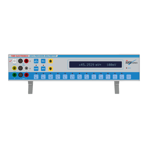
Time Electronics 5075 Installation instructions

5075
Precision
Digital Multimeter
GPIB Command Guide
Time Electronics Ltd
Unit 11 Botany Industrial Estate
Tonbridge, Kent, TN9 1RH
Tel: 01732 355993 Fax: 01732 770312
E-Mail: mail@TimeElectronics.co.uk
Web Site: www.TimeElectronics.co.uk
V1 07/12/06

1
IEEE Operation
1.1. Introduction
The IEEE - 488 interface, sometimes called GPIB (General Purpose Interface Bus) or the HPIB
(Hewlett Packard Interface Bus) allows remote control of the instrument by a suitable computer
or controller.
Repetitive calibration work can be speedily and accurately carried out, giving printed results if
required.
The 5075 is compatible with the IEEE - 488 (1978) interface bus.
The IEEE - 488 standard defines a complete interface system for the interconnection of
instruments and computers using a bit parallel, byte serial bi-directional bus. Protocols,
connections and cables are also defined, enabling computer controlled systems to be quickly
realised.
The main limitations of the IEEE are :-
1) A maximum of 15 devices on the bus.
2) The maximum bus length should not be greater than 20m or number of devices x 2,
which ever is the shorter.
1.2. Data Transfer and Device Addressing
Before a controller can send data it has to identify the recipient. Each device on the IEEE is
given an address to which it will respond when called by the controller, in this way data can be
transferred between selected devices in an orderly manner.
The rate at which data is transferred is controlled by handshake signals, the speed being
governed by the slowest device active on the bus.
Set baud rates are therefore unnecessary with this system.
1.3. IEEE Cables
The IEEE - 488 cable contains 24 wires terminated at both ends with identical plug/sockets
which allow for daisy - chaining of additional cables to extend the bus.
Cables used on IEEE systems are available in various lengths to suit different layouts.
1.4. IEC Bus Connections
Users requiring to connect the DMM to a European standard bus (IEC - 625), must be aware of
the differences in connector pin assignments from the IEEE bus and provide a suitable
interface.
Table 6.1 compares the pin designations for each standard.

2
1.5. IEEE Connector
The pin connections and dimensions of the IEEE connector are illustrated in Figure 6.1 and in
Table 6.1.
Figure 6.2 illustrates the connections.
IEEE - 488
STANDARD
IEC - 625
PIN NUMBER
FUNCTION FUNCTION
1
2
3
4
5
6
7
8
9
10
11
12
13
14
15
16
17
18
19
20
21
22
23
24
DIO 1
DIO 2
DIO 3
DIO 4
EOI
DAV
NRFD
NDAC
IFC
SRQ
ATN
SHIELD
DIO 5
DIO 6
DIO 7
DIO 8
REN
GND 6
GND 7
GND 8
GND 9
GND 10
GND 11
LOGIC GND
DIO 1
DIO 2
DIO 3
DIO 4
REN
EOI
DAV
NRFD
NDAC
IFC
SRQ
ATN
SHIELD
DIO 5
DIO 6
DIO 7
DIO 8
GND 5
GND 6
GND 7
GND 8
GND 9
GND 10
GND 11
Table 6.1

3
1.6. IEEE Address Selection
Before operating the DMM over the IEEE bus, set the address on the rear of the unit to the
required address and operating mode.
Addresses 0 and 16 are reserved for recalibration and should not be used unless recalibrating
the instrument. Address 31 is used to select self test mode.
The first five switches set the IEEE address and the last three switches are used to select the
instruments operation mode. The last three switches are normally set to off but may be used as
follows:
Switch 6 - Disable IEEE talk (transmit) mode.
Switch 7 - Disable IEEE listen (receive) mode.
Switch 8 - Dual Primary Addressing mode. In this mode, the unit will respond to two primary
addresses differing only in the least significant bit. For example, if the unit address selection
switches are set for an address of 8, the unit will also respond to address 9.
NOTE: The instrument only reads the address switch upon power up. Therefore if the IEEE
address is changed it will be necessary to switch the unit off and on again.
1.7. Local/Remote Operation
The 5075 is switched into remote operation when a valid command is received on the IEEE bus.
The unit will remain in remote control until the MENU/LOCAL key is pressed on the DMM or
until the unit is switched off.
1.8. Interface Clear Command - IFC
This command initiates a complete reset of the unit, which is then unable to respond to any
further IEEE commands for 1 second.
1.9. IEEE Command Format
IEEE commands are comprised of characters from the ASCII set. A series of commands can
be used to simulate the manual operation of the unit.
The commands must be in one of the following formats:
1) A single upper case character (A to Z).
2) An upper case character followed by a number.
Commands may be sent individually or build into a string separated with a slash character (/).
A command string may take the form of -
Terminator Character
IOCTL #2, "FO / R8/ X4" + CHR$ (13)
Controller specific command. 5075 command string.

4
The controller specific command is an instruction to the IEEE controller to read or write the
following string to the device on the bus. This command may vary considerably between
controllers and the example shown is a typical QuickBasic language by Microsoft command.
Refer to your IEEE controller for specific commands.
The 5075 command string consists of commands from the 5075 Instruction set. These
commands will instruct the 5075 to perform measurement functions or other operations.
1.10. Terminating Character
All command strings must end with a terminator character for the string to execute. This may
be either a line feed or carriage return character as set by the T1 or T2 command.
1.11. IEEE Command Execution
Before an IEEE command can be executed the following conditions must be met.
1) The IEEE address and the talk/listen switches set correctly on the rear panel switch.
2) The command must be a valid command (invalid commands are ignored).
3) The command must be followed by a valid terminator character.
1.12. IEEE Command List
RANGE DC VOLTAGE AC VOLTAGE DC CURRENT AC CURRENT OHMS CAPACITANCE FREQUENCY
A0
A1
AUTORANGE OFF
AUTORANGE ON
R1
R2
R3
R4
R5
R6
R7
R8
R9
R10
R11
R12
R13
R14
R15
R16
R17
R18
R19
R20
R21
R22
R23
3mV
10mV
30mV
100mV
300mV
1V
3V
10V
30V
100V
300V
1kV
3kV
10kV
30kV
3mV
30mV
300mV
3V
30V
300V
3kV
3uA
10uA
30uA
100uA
300uA
1mA
3mA
10mA
30mA
100mA
300mA
1A
3A
10A
30A
3uA
30uA
300uA
3mA
30mA
300mA
3A
30A
30mW
100mW
300mW
1W
3W
10W
30W
100W
300W
1kW
3kW
10kW
30kW
100kW
300kW
1MW
3MW
10MW
30MW
100MW
300MW
1GW
30nF
300nF
3uF
30uF
300uF
100kHz

5
1.13. Transmitted Value Format
When the ‘D’ command has been sent to the instrument via the IEEE bus, the present value will
be sent back.
This may take the format of an 8 digit reading either with the function or without depending upon
the output mode (E0 or E1).
i.e. ± 1. 2345678± 03 Or with the function - ± 1. 2345678± 03DCV
MEASUREMENT FUNCTION
F0
F1
F2
F3
F4
F5
F6
F7
F8
F9
F10
DC VOLTAGE
AC VOLTAGE
AC/DC COUPLED VOLTAGE
DC CURRENT
AC CURRENT
AC/DC COUPLED CURRENT
2 WIRE RESISTANCE
4 WIRE RESISTANCE
FREQUENCY
CAPACITANCE
DIODE CHECK
SINGLE CHARACTER COMMANDS
Z
T
D
*
NULL
TAKE READING
TRANSMIT VALUE TO IEEE
RESET
OUTPUT MODES
E0
E1
OUTPUT VALUE
OUTPUT VALUE AND
FUNCTION
RESOLUTION
N4
N5
N6
N7
4 DIGITS
5 DIGITS
6 DIGITS
7 DIGITS
TERMINATOR CHARACTERS
V1
V2
CARRIAGE RETURN -
(DEFAULT)
LINE FEED
FILTERS
X0
X1
X2
X3
X4
X5
X6
X7
X8
X9
Y0
Y1
W0
W1
FILTER OFF
150ms
250ms
500ms
1s
2s
4s
8s
16s
32s
ADF OFF
ADF ON
ANALOGUE FILTER OFF
ANALOGUE FILTER ON
PRT MODE
U0
U1
PRT MEASUREMENT OFF
PRT MEASUREMENT ON
SRQ STATUS
B0
B1
DISABLE SRQ
ENABLE SRQ
SCANNER CHANNEL
S0
S1
S2
S3
S4
S5
S6
S7
S8
S9
S10
S11
S12
S13
S14
S15
S16
S17
S18
S19
S20
OFF
1
2
3
4
5
6
7
8
9
10
11
12
13
14
15
16
17
18
19
20
MENU FUNCTIONS
J1
J2
J3
J4
J5
J6
J7
J8
J9
J10
SERIAL No.
CERTIFICATE No.
CALIBRATION DATE
CALIBRATION DUE DATE
CALIBRATION TEMPERATURE
CALIBRATION PERIOD
DATE
TIME
INTERNAL TEMPERATURE
IEEE ADDRESS
OHMS COMPENSATION MODE
O0
O1
COMPENSATION OFF
COMPENSATION ON

6
1.14. Programming Example
The following simple demonstration program written in Basic takes one reading from the DMM.
The IEEE interface card in your computer may be different from the one used in this example
program.
The following program will allow the operator to send a valid IEEE command to the DMM, to set
a range or filter and then display the result.
100 REM *** IEEE CONTROL DEMO PROGRAM
101 OPEN "IEEECTRL" FOR RANDOM AS #1 `Open Control File
102 OPEN "IEEEDATA" FOR RANDOM AS #2 `Open Data File
220 T$ = CHR$ (13) + CHR$ (10) `Set the terminator character
230 CLS
231 INPUT "Enter IEEE Address of DMM" ; IE$ `Select IEEE address
232 IOCTL #1, IE$ `Send IEEE address
233 INPUT "ENTER COMMAND (X TO EXIT, Q TO TAKE READING" ; C$
234 IF C$ = "X" THEN END
235 IF C$ = "Q" THEN GOSUB 400 : GOTO 300
236 IOCTL #2, C$ + T$ `Send command to IEEE
237 GOTO 300
238 REM *** TAKE READING FROM DMM
239 IOCTL #2, "T" + T$ `Instruct DMM to take reading
240 FOR I = 1 TO 1000 : NEXT I
241 IOCTL #2, "D" + T$ `Transmit reading from DMM
242 R$ = IOCTL$ (2) `Readback from IEEE Bus
243 PRINT R$ `Print reading
460 RETURN

7
Guarantee Period
The 5075 is guaranteed against defects in materials and workmanship for a period of one year
from its delivery to the customer.
We maintain comprehensive after sales Facilities and the unit can, if necessary be returned to
us for servicing.
During this period, we will at our discretion repair or replace the defective item.
For servicing under guarantee, the instrument type and serial number must always be quoted,
together with details of any fault and the service required. The purchaser of the instrument
must pay all shipping charges to manufacturer. We will pay return shipping charges.
This guarantee is void if servicing has been attempted by an unauthorised person or agent.
If during the guarantee period, failure is due to misuse or abuse of the unit, the repair will be put
in hand without delay and charged unless other instructions are received.
We guarantee that the software and firmware for this instrument will execute its programmed
function. We do not guarantee that the operation will be uninterrupted or error free.
Please note that if you require a new UKAS Certificate during the warranty period, this will be
charged at the current rate on our price list.
Service After Guarantee Period
Even after the guarantee period has expired, we can still recalibrate and service your
instrument.
As the manufacturer, we have the specialised knowledge needed to keep your instrument in
peak condition and we also maintain a comprehensive spare parts service.
Please enclose details of the service required and your full company details including a contact
name.
Returning Instruments
When returning instruments, please ensure that they have been adequately packed, preferably
in the original packing supplied. We will not accept responsibility for units returned
damaged.
Please ensure that all units have details of the service required and all relevant paperwork
including contact name, address and telephone number.
Time Electronics Ltd
Unit 11 Botany Industrial Estate
Tonbridge, Kent, TN9 1RH
Tel: 01732 355993 Fax: 01732 770312
Web Site: www.TimeElectronics.co.uk
Other manuals for 5075
2
Table of contents
Other Time Electronics Multimeter manuals