TimeTec FingerTec Face ID 4 FMM User manual

Face ID 4/4D FMM
User Guide

Copyright Notice
All rights reserved. No part of this book may
be reproduced or transmitted in any form
or by any means, electronic or mechani-
cal, including photocopying, recording, or
by any information storage and retrieval
system, without written permission from
Timetec Computing Sdn Bhd. Every pre-
caution has been made to supply complete
and accurate information. Information in
this document is subject to change without
prior notice.
Disclaimer
No person should rely on the contents of this
publication without first obtaining advice
from a qualified professional person. The com-
pany expressly disclaims all and any liability
and responsibility to any terminal or user of
this book, in respect of anything, and of the
consequences of anything, done by any such
person in reliance, whether wholly or partially,
upon the whole or any part of the contents of
this book.
TimeTec compuTing Sdn Bhd

Contents
5-6 Chapter 1
GETTING STARTED
Viewing the User Guide in the Internet
Accessories
Printed Materials
Activating Terminal
Registering Terminal
7-9 Chapter 2
BASICS
Introduction to Terminal
Terminal Overview
Main Menu
Battery
• External power supply
Cleaning Terminal
• Cleaning The Body
Restarting and Resetting Terminal
• Restarting the terminal
• Resetting the Terminal
10-14 Chapter 3
USERS
Introduction
• Voice Message
Methods of Enrollment
• Face Enrollment
• Fingerprint Enrollment
• Card Enrollment
• Password Enrollment
Menu Options
• Edit User
• Delete User
• Display Options
• User Role
• Defined Role
• Assign Role
15-23 Chapter 4
INSTALLATIONS & CONNECTION
Installations
• Mount On Wall
Communications
• USB Port
• TCP/IP Port
• Power Supply Port
• Access Control Port
• External Alarm Port
• COM Key
Configure TCP/IP connection
Configure USB Flash Disk
• Download
• Upload
• Download Option
Configure WiFi
Configure Cloud Server
Connecting The Terminals to TCMS V3/Ingress
Installation and Setup of TCMS V3/Ingress
Connecting The Terminals to TCMS V3/Ingress
• Determining Terminal Number
• Using TCP/IP
• Setting Up Netmask and Gateway
Communication Key

24-28 Chapter 5
SYSTEM
Setup Date and Time
• To use Daylight Savings Time (DLST)
Attendance Record Storage Option
• Duplicate Punch Period
• Camera Mod 8
• Display User Photo
• Attendance Log Alert
• Cyclic Delete ATT Data
• Cyclic Delete ATT Photo
• Conrm Screen Delay(s)
• Face Comagrison Interual
• Expiration Rule
Face Options
Reset Options
29-32 Chapter 6
PERSONALIZATION
User Interface
Voice
Bell
• Edit and Delete a Preset Schedule
• Output to External Bell Siren
Clocking State Options
• Clocking State Mode
• Clocking State Required
Shortcut Key Mappings
33-36 Chapter 7
DATA MANAGER
Delete Data
Backup Data
Restore Data
Access Control (Face ID 4D)
• Access Control Option Settings
TimeZone
Holidays
Access Group Settings
37 Chapter 8
ATTENDANCE SEARCH
38-39 Chapter 9
SHORT MESSAGE DISPLAY
Add a Short Message
• Select Message Type
Public, Personal and Draft List
Message Option
40 Chapter 10
WORK CODE
Adding a Work Code
All Work Codes
Work Code Options
41 Chapter 11
DIAGNOSTIC
42 Chapter 12
SYSTEM INFO
Device Capacity
Device Info
Firmware Info
43-44 TROUBLESHOOTING
“Unable to Connect”
“Admin Arm”
The LED is Blinking All The Time
RFID Card No Respond
No Sound
5
Metal Back Plate
Chapter 1
Getting Started
Viewing the User Guide in the Internet
The User Guide is available in the package when you purchased the terminal. The User
Guide is also available online at http://www.fingertec.com and http://user.fingertec.com.
Choose the language that you prefer for your User Guide.
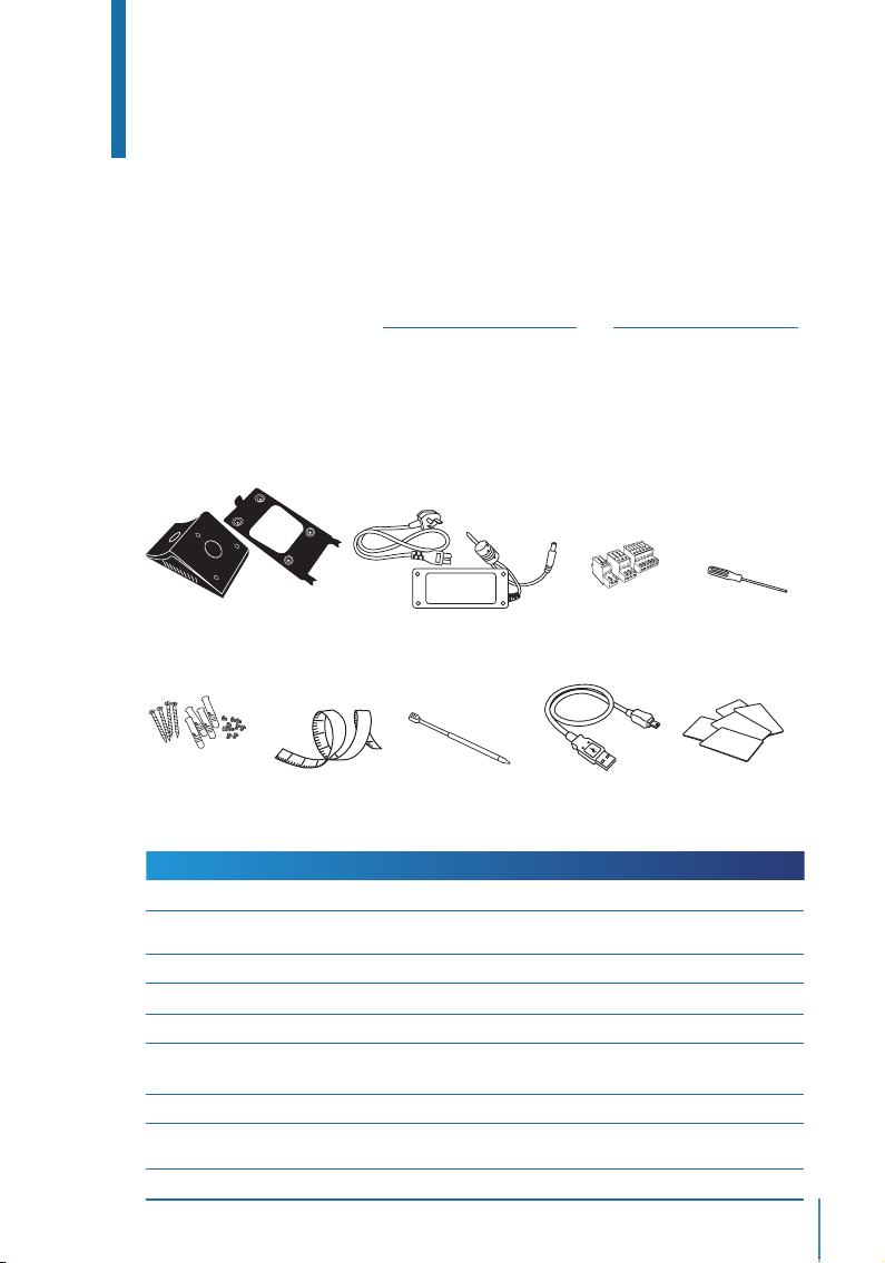
Terminal Included Accessories
1
2
3
12
11
10
25
ITEM
Metal Back Plate
DC 12V Power Adaptor
Connection Wires
Screwdriver
A Packet of Screws and Bolts
Measurement Tape
Stylus
USB Extension
RFID Cards (5 pieces)
FUNCTION
Secure this plate on top of the rubber cushion and place the terminal onto it.
Connect the power adapter to the terminal and plug it into a standard
power outlet to charge the terminal.
To connect the wires to a door lock or a doorbell if required.
T10 screwdriver to open the back plate of the terminal for installation
Use the bolts to mount the back plate of the terminal on the wall.
To measure the installation height to achieve optimum performance for
terminal.
For easy navigation on the touch screen LCD panel.
To connect to the USB port of a computer for uploading and downloading
of data.
FingerTec provides extra cards for RFID (5pcs) and Mifare Card, (1pc).
A Packet of
Screws and Bolts
Screwdriver
DC 12V Power Adapter
Connection Wires
*Face ID 4d only
RFID Cards (5 pieces)
Measurement Tape Stylus USB Extension

6
Activating Terminal
Every FingerTec Time Attendance and Access Control model comes bundled with a unique
license key. To start using the terminal with TCMS V3 (for Face ID 4) or Ingress (for Face ID
4d), you must connect the terminal to the software and perform online activation. The
software reads the serial number of your terminal and sends it for verification at the Fin-
gerTec server via Internet.
In case you do not have an Internet connection, you would need to do an offline activation.
Please send the serial number and models of your terminals to
support@fingertecaustralia.com.au to request for a product key.
Registering Terminal
Make sure that you register your Face ID 4d warranty with us at
https://www.fingertec.com/ver2/english/e_warranty.htm
7
Chapter 2
Basics
Introduction to Terminal
Introducing Face ID 4, the new facial recognition technology product combined with
card technology. Face ID 4 can identify an identity in split seconds without any con-
tact or hassle. It only requires a user to look at the machine to get verified. Face ID 4 is
loaded with powerful microprocessor that can process facial authentication method for
accurate personal identification and for collection of precise data for time attendance
and door access* (Face ID 4d only). In addition, the Face ID 4 terminal accepts card veri-
fication as an added security measure. If you are looking for a contactless, hassle free
biometrics product, choose Face ID 4. With one look you are good to go!
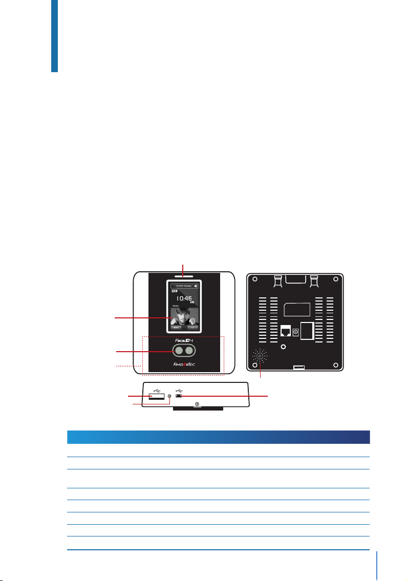
Terminal Overview
ITEM
Card Induction Area
Touch Screen LCD
LED Light Indicator
Speaker
Twin Face Camera
Reset Button
USB Port
Micro USB Port
FUNCTION
Read the card information based on the card system of Face ID 4.
Touch to access into Face ID 4 system to do conguration.
Indicate the status of reader. Green indicates standby mode or verication is suc-
cessful. Red indicates problem or verication has failed.
Emit instructions from Face ID 4.
Capture face images in a few directions.
To restart the machine.
Connect the USB ash disk to download/upload data from/to Face ID 4.
Connect Face ID 4 directly to pc/laptop to download/upload data with software.
Restart Button
Card Induction
Area
Touch Screen
LCD
Twin Face Camera
Speaker
LED Light Indicator
USB Port
w
Restart
Micro USB port
8
Battery
Terminals operate using power supply from a standard power outlet. Inside the termi-
nal, there is an RTC battery for the running of the clock. Charge the terminal for at least
3 hours straight before you start using it. When there is a serious delay in time or the
clock keeps on restarting, the RTC needs to be replaced.
External power supply
Mini UPS (uninterrupted power supply) 5V and mini UPS 12V provide mobile power
supply to the terminals. Charge the mini UPS sufficiently for optimum performance.
Refer to http://accessory.fingertec.com for more information about accessories.
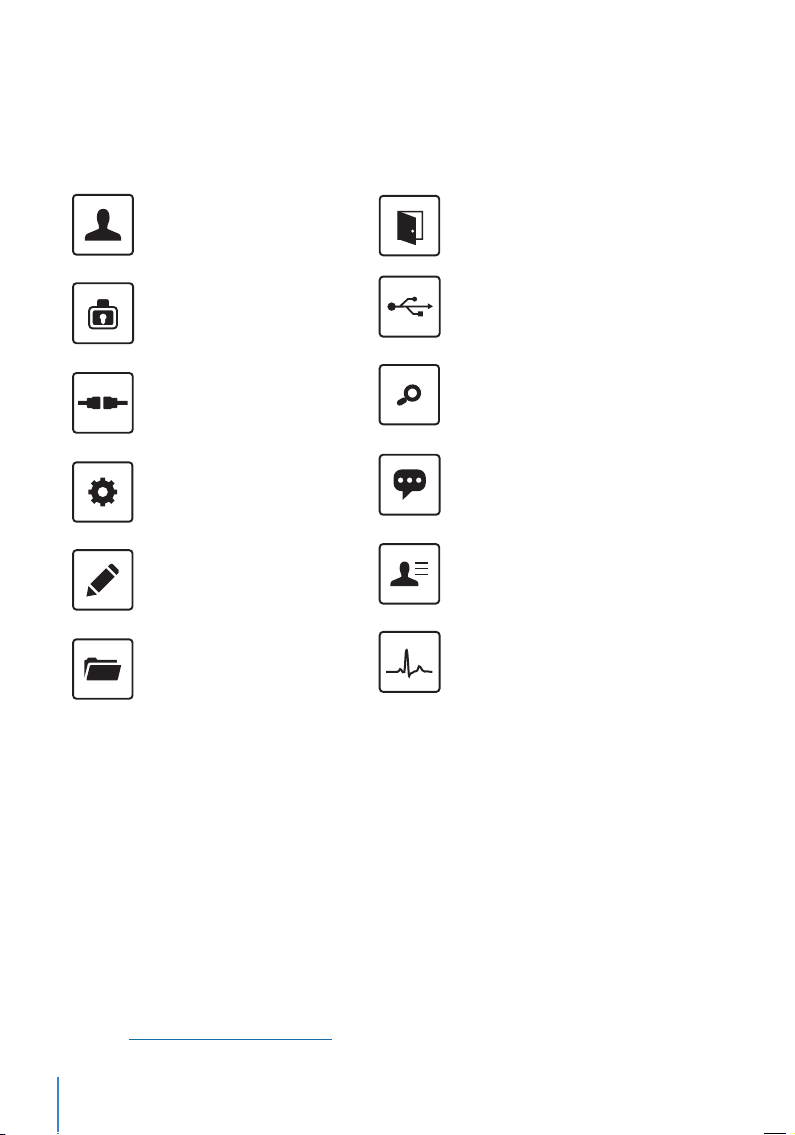
User Mgt
Enroll users/ manage user data.
User Role
Assign privilege to users for data secu-
rity.
COMM.
Setup FingerTec terminal communica-
tion with computer through LAN, RS232
and RS485. Set security password of the
device for a secure data transfer.
System
Congure the settings of the FingerTec
terminals from general to display set-
ting to ngerprint, and reset the termi-
nal to default settings.
Personalize
Adjust the date/time, Voice, bell sched-
ules settings of the terminal.
Data Mgt
To delete/backup or restore data.
Main Menu
Access Control
Congure door access settings in ter-
minal.
USB Manager
Upload and download data and infor-
mation to and from FingerTec terminal
using a USB ash disk.
Attendance Search
Check attendance and transaction logs
that are available in FingerTec termi-
nals and perform housekeeping in the
machine.
Short Message
Create & manage Short Message dis-
play.
Work Code
Create & manage workcode function-
ality.
Autotest
Tests that can be done on the FingerTec
terminal on various aspects.
Sys Info
Show basic information of the device,
capacity and rmware informatio

9
Cleaning Terminal
Cleaning The Body
Use a dry cloth to clean the terminal’s body. Do not use any liquids, household cleaners,
aerosol spray, solvents, alcohol, ammonia and abrasive solutions to clean the body of the
terminal because it could damage it.
Restarting and Resetting Terminal
If something isn’t working right, try restarting or resetting the Face ID 4.
Restarting the Terminal
At the bottom of Face ID4, look for the Restart button use a pin, press the button
once to restart the terminal.
Resetting the Terminal
Go to Menu >Data and click on Restore to Factory Settings.
Press Yes to confirm. Resetting of Face ID 4 will cause all your settings to return to
the original factory settings

10
Chapter 3
Users
Introduction
FingerTec devices recognize users by face recognition, card access or a set of pin num-
bers. The Date, Time Data and User ID will be stored in its internal storage upon verifica-
tion and will be used to generate reports in accordance with the user’s attendance.
Privileges can be assigned accordingly based on individual permissions. Likewise, a Sys-
tem Administrator can have his rights restricted or be given full control. Access controls
such as the ability to modify settings within the menu will be barred when a System Ad-
ministrator has been assigned to a device. The role of an administrator plays a crucial role
in the vitality of the data in these devices.
For example, Network Administrator(s) can be allowed to configure communication set-
tings but not to enroll new users.
Three levels of authority govern each device:
• Super Administrator
The top of the hierarchy, Super Administrators have, full access to all functions.
• Administrator
The rights of an Administrator are limited by the permissions granted by the Super Ad-
ministrator. For example, a Network Administrator can be allowed to configure commu-
nication settings but are not allowed to enroll users.
• User
Normal users have no access to any functions within the device.
By default, every user enrolled is a normal user. Super Admin and Administrator roles are
allocated from the list of normal users, either directly from the terminal or assigned via
our software.

11
VOICE / MESSAGE
“Verified”
“Admin Affirm”
“Invalid ID”
WHAT DOES IT MEAN?
Identity verication is successful, the terminal stores the transaction logs and
opens the door (if connected to door access)
You are not an administrator of the system and you cannot access Menu page.
For 1:1 verication, User ID entered does not match with Face.
Voice Message
Methods of Enrollment
Face Enrollment
During enrolment on Face ID 4, please stand straight and do not move your face or
body, and make sure that your face is calm with no extreme expression. For height be-
tween 150cm to 180cm, recommended distance between Face ID and user is 0.5m.
Follow the steps below to enroll a Face:
Step 1: Press Menu >User Mgt >New User
Step 2: User ID >Key in User ID This is the unique ID number that represents the user
in the devices and software. Make sure you do not use duplicated ID. The maximum
length is 9-digits
Step 3: Select Face >Follow the voice and interface prompts to move back and forth
to place your eyes within the green box >Register Face success
Step 4: Press User Role >Select Role >Select Normal User >Press OK to save
Cannot enroll duplicate face, otherwise device will show message ‘Duplicated
Face’
Card Enrollment
Please check the technical specifications of the device to ensure that this function is
supported before continuing. The default card type is 64-bit, 125kHz RFID card. MIFARE
and HID card systems are available upon request.
Follow the steps below to enroll a card:
Step 1: Press Menu >User Mgt >New User
Step 2: User ID >Key in User ID
This is the unique ID number that represents the user in the devices and software.
Make sure you do not use duplicated ID. The maximum length is 9 digits

12
Step 3: Select Card >Wave card at the induction area >Screen displays the card ID >
Press OK to save
Step 4: Press User Role >Select Role >Select Normal User >Press OK to save
Select Super Admin or other defined role(s) you wish to assign to this user.
Refer to page 13 for more details regarding User Role
Password Enrollment
Password verifications have a lessened security presence in Attendance Reporting and
Access control systems. Despite this, passwords are generally the primary preference for
enrollment. FingerTec devices can accept up to 8-digit passwords in numeric format.
Follow the steps below to enroll password:
Step 1: Press Menu >User Mgt >New User
Step 2: User ID >Key in User ID
This is the unique ID number that represent the user in the devices and software.
Make sure you do not use an existing ID. The maximum length is 9 digits
Step 3: Select Password
Step 4: Insert password for the 1st time >Press OK >Re-enter the password to con-
firm
Step 5: Press User Role >Select Role >Select Normal User >Press OK to save
Select Super Admin or other defined role(s) you wish to assign to this user.
Refer to page 13 for more details regarding User Role
Edit User
Name Change, user role, deletion or re-enrollment of fingerprints, card and/or pass-
words can be modified after the enrollment process. However the user ID is permanent
and cannot be changed.
To edit user information:
Step 1: Press Menu >User Mgt >All User >User ID
Step 2: Key in User ID >Press OK Button > Select Edit
Step 3: Select the credentials to be edited >Save and Exit.
13
Delete User
Only an administrator can perform user deletion at the terminal.
To delete user(s):
Step 1: Press Menu > User Mgt > All User > User ID
Step 2: Key in User ID > Press OK Button > Select Delete
Step 3: Select Delete User, User Role, Fingerprint or Password
Step 4: Press OK Button to delete > Select OK to confirm deletion > ESC to exit.
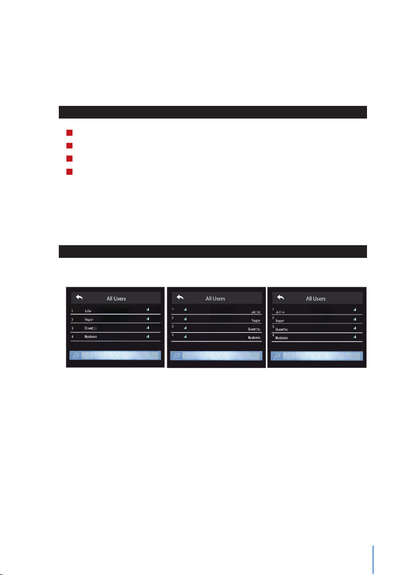
Display Option
Users can choose the display style of their credentials either to be in. Single Line, Mul-
tiple Line & Mixed Line.
The different types of display are shown below:
Press Menu > User Mgt > Display Style > Select the type of Display > ESC to Exit
SINGLE LINE MULTIPLE LINE MIXED LINE
User Role
Employees with Super Admin rights are granted limitless access to all settings and sys-
tems within the terminal in addition to the ability to enroll new users. Super Admin can
also perform system Reset.
Employees with Normal User rights are only able to log in their attendance at a terminal.
They are unable to access the menu to modify settings within the menu.
In addition to the three defined roles, you are given the option to configure 3 different
subsets.

14
Dene Role
You can define what the administrator is allowed to do at the device. A maximum of
three different role sets can be configured. For example, you create a role called Network
Admin, and limit his access to the Network option only. Therefore, he is unable to enroll
new users or configure device settings.
To set the define user role:
Step 1: Press Menu >User Role
Step 2: Select User Defined Role >Press OK >Press OK again to enable the selected
Role
Step 3: Rename the Role >Define User Role >Save and Exit.
Once these roles have been defined, they will appear in the Users tab where you
can assign employees accordingly.
Assign Role
To define roles for new employees:
Step 1: Menu >User Mgt >New User >User Role
Step 2: Select the role to assign to the employee >Save and Exit.
To define roles for existing employees:
Step 1: Menu >User Mgt >All Users >Press OK >Select the User ID >Press OK >Edit
Step 2: User Role >Select the role to assign to the employee >Save and Exit

15
Back Plate
4 feet / 1.2 meter
(recommended)
support@finger t ec.com
Chapter 4
Installations & Communication
Installations
FingerTec terminals offer several connections for power and communications. Installa-
tions of FingerTec time attendance terminals are simple.
Mount On Wall
• After measuring the height accordingly and make relevant marking on the wall, drill
the screws into the wall to secure the back plate.
• Attach the terminal to the back plate and tighten the screws.
Communications
Connection points for power and communica-
tion are available on top of the terminals. Refer
to the following diagrams for the terminals you
require.
TCP/IP Port
TCP/IP Power Port

16
This is only available
for Face ID 4d
DC12V 3A
Power Supply
TCP/IP Port
TCP/IP
POWER SUPPLY (A)
DC12V 3A
Power Supply
GND
+12V
Alarm output
Door Lock
System
CONNECTOR PINS
For NC (normally close) door lock system
For NO (normally open) door lock system
2
3
A
C
EM Lock
(NC)
Emergency
Break Glass
(NC)
Override
Key Switch
(NC)
Release
Button
GND 12V NC1 COM1 NO1
SEN GND BUT NO2 COM2 NC2
DC12V 3A
+
+
Alarm Device
(NC)
Alarm Device
(NO)
Door
Sensor
Please refer to the AdapTec Plus Installer Manual if you are using AdapTec Plus.
2
3
A
C
EM Lock
(NO)
Emergency
Break Glass
(NO)
Override
Key Switch
(NO)
Release
Button
GND 12V NC1 COM1 NO1
SEN GND BUT NO2 COM2 NC2
DC12V 3A
+
+
Alarm Device
(NC)
Alarm Device
(NO)
Door
Sensor
For access control, Face ID 4d

17
1 8
TOP
FRONT
1 8
CONNECTOR PIN CABLE COLOR CONNECTOR
TX+ 1•White/Orange •1 TX+
TX- 2•Orange •2 TX-
RX+ 3•White/Green •3 RX+
4•Blue •4
5•White/Blue •5
RX- 6•Green •6 RX-
7•White/Brown •7
8•Brown •8
JOINT 1 PIN JOINT 2 PIN
TX+ 1 ••3 RX+
TX- 2 ••6 RX-
RX+ 3 ••1 TX+
RX- 6 ••2 TX-
USB Port
Linking with USB flash disk for remote data
transfer.
TCP/IP Port
Connect with CAT 5 cable for LAN connection,
one end to this port and another end to the
computer’s TCP/IP Port.
TCP/IP for Single Connection – Linking the ter-
minal to a single computer using TCP/IP re-
quires Ethernet 10/100Base-T Crossover Cable.
The cable can be used to cascade hubs or to
connect Ethernet stations back-to-back with-
out a hub. It works with both 10Base-T and
100Base-TX.
TCP/IP for Network Connection – Linking the terminals to multiple computers using TCP/IP
requires Ethernet 10/100Base-T Straight Thru Cable or “whips”. The cable works with
both 10Base-T and 100Base-TX, connecting a network interface card to a hub or net-
work outlet.
Power Supply Port
Insert the Power Adapter point to this port for power.
Access Control Port *for Face ID 4d only
Linking Face ID terminal to door lock system.
External Alarm Port *for Face ID 4d only
Connect to External Siren for Door security
FingerTec devices offer several types of communication mediums for data transfer that
allows you to share employee credentials across all devices within the network without
re-enrolling users. Employee attendances are downloaded into our software for easy
viewing, analysis and reporting.

18
We recommend that you delete the attendance records upon completion of the down-
load process. The deletion process can be done manually at the device or commands via
the software’s interface.
This chapter will provide instructions to guide you in setting up the correct parameters to
establish connection between your devices and the software. The available communica-
tion methods are listed below:
• TCP/IP
• WiFi (Wireless)*
• Cloud Server
• USB drive
*This communication method is only available upon request
Configuring your Device ID should be your first step before continuing with the above
communication methods. It is crucial that each terminal’s unique ID is identified and set
apart. By default, all our Device IDs are set to “1”, therefore you must change the Device ID
manually if multiple devices are installed.
To change the Terminal ID:
Step 1: Menu >Comm. > PC Connection >Device ID >OK
Step 2: Insert new ID by pressing the keypad >OK to Save >ESC to Exit
COM KEY
Create password for a specific terminal here. The security password known as COM Key
is intended for extra security. To conect the terminal with the sofgtware, the COM Key
inserted in the Software must be the same as the one inserted in the terminal or else the
connection will not be established even though the activation key and product key are
correctly inserted.
To set the Comm. Key
Step 1: Menu >Comm. > PC Connection >Comm. Key
Step 2: Insert the password by pressing the keypad >OK to Save >ESC to Exit

19
Conf.igure TCP/IP connection
Internet Protocol (IP) is a unique numeric designation of each device within a network.
Without an assigned IP Address, it would make identifying a specific terminal difficult.
The default IP address of each terminal is 192.168.1.201. Connect your terminal via a
RJ45 (LAN cable) to connect to your local area network.
To change the IP address:
Step 1: Menu > Comm. >Ethernet > IP Address > OK
Step 2: Insert the IP Address > Press Down arrow to go to the next column
See below to understand every column.
• IP Address: Known as Internet Protocol Address, the default configuration is
192.168.1.201.
• Subnet Mask: Set to 255.255.255.0 by default, this is used to manage a specified net-
work range. You may change the subnet mask if you have multiple networks in your
company.
• Gateway: By default, it is configured as 0.0.0.0. Only configure the gateway if the
device and PC are on different IP ranges.
• DNS: Domain Name System. By default, the DNS has been configured as 0.0.0.0. If you
are using your own internal DNS servers, please change your DNS to ensure that it is
reflected accordingly.
• TCP COMM Port: The default port is 4370. Only change the number if your network is
unable to utilize this port.
• DHCP: Dynamic Host Configuration Protocol. It’s used to allocate dynamic IP address-
es to clients on a network.
Congure USB Flash Disc
USB drives can be utilized to transfer data between FingerTec devices and software if a
cable is unavailable. You can export employees’ attendance records (transaction logs)
from the device to the USB drive, and import the data from the drive directly to your
management software and vice versa.
Download
To copy data from a device into a USB drive. Attach the USB drive to the device.e

20
To download the data:
Go to Menu >USB Manager >Download
You can select the following data type to copy into the USB drive:
• Download Attendance Data: Download attendance data.
• Download User Data: Download employees’ data (face/fingerprint templates, pass-
word, card ID, names).
• Download User Portrait: Download employees’ photos.
• Download Attendance Photo: Download photos captured while an employee is suc-
cessfully verified. The photos are in JPEG format.
• Download Blacklist Photo: Download the photo (captured while employee fails to
verify at the device) into USB device. The photos are in JPEG format.
• Download Work Code: Download the work code ID.
• Download Short Message: Download the short message.
Upload
Uploading is the process of copying data from a USB drive into a device. The data has to
be copied from the software to the USB Drive. To begin uploading your data, connect
the USB to your device
To uploading the data:
Go to Menu >USB Manager > Upload
• Upload Screen Saver: Upload photos (used as a slide show) in JPEG format into the
device. The name of file must start with “ad_”.
• Upload Wallpaper: Upload a photo (used as wallpaper at the main screen) in JPEG
format into your device. An example of the file’s naming convention - “1-10.jpg”
• Upload User Data: Upload all user information.
• Upload User Portrait: Upload employees’ photos.
• Upload Work Code: Upload the work code ID.
• Upload Short Message: Upload the short message.
Download Options
You can configure your device to encrypt data and transaction logs when downloading
onto a USB drive to avert alterations made by staff members. Logs can be chosen for
deletion after being downloaded into your USB drive to free up disk space.
Go to Menu >USB Manager >Download Options >Press OK to Enter >Select either
Encrypt Attendance Data or Delete ATT data >Press OK to either turn the function on
or off.
This manual suits for next models
1
Table of contents
Other TimeTec Touch Terminal manuals


