Tin Lee Electronics CR7-3AE User manual

Model CR7-3AE is a high attenuation bandstop. It is installed
inline with cable TV signal, and is designed to delete TV channel
3 from the CATV spectrum, to allow insertion of a local channel
3 signal (e.g. modulator ch.3 from DVD, Sat.Rec., Camera).
Model CR7-3AE will pass all other channels, with low impact on
upper and lower adjacent channels 2 and 4. This model is also
available for channels 2 thru 6, 95(A5)-99(A1). Specify channel
(CR7-#AE), e.g., CR7-6AE.
• Stopband: >50 dB minimum
• Low impact on adjacent channels
• Bandwidth: DC-1000 MHz
• Passband thru loss: 1.5 dB ± .5 dB
• Good temperature stability 0° to +35° C
• Easy installation - no power or adjustments
• Supplied with final production graph
Economical Single Channel Deletion Filters - Low Band Series
CR7-3AE channel 3“Brickwall” Bandstop
CR7-3AE Specifications
Example graph - CR7-3AE
Channels
available Passband
(MHz) Passband
Loss (dB) * Adjacent Carrier Loss
Lower Upper
2, 3, 4 DC-1000 1.5 ± .5 < 6.0 < 4.5
5, 6 DC-1000 1.5 ± .5 < 6.0 < 5.0
95 to 99 DC-1000 1.5 ± .5 < 6.5 < 5.5
General Specifications
Stopband (dB): >55 carriers, >50 in-band
Connectors: F-type female
Impedance: 75 ohms
Operating
Temperature 0 to +35 ° C (32 to100 ° F)
Mounting Wall
Weight 2.0 (lbs)
Dim (in): 7.5L x 4.0 W x 2.0 H
File: CR7-3AEE-info.pub 1/7/08
Tin Lee Electronic Ltd. Canada Tel.: (416) 690-3196 Fax(416) 690-0932 Email: [email protected] Website: www.tinlee.com

• Referring to hookup diagram below, deletion filter ,CR7-3AE, is connected inline with Cable TV signal
to remove designated channel only (ch.3).
• Optional bandpass, CF7-3AE, is installed at modulated Satellite Receiver ch.3 output to prevent adja-
cent channel interference.
• The Cable TV signal and Ch.3 source can be combined with 2-Way Signal splitter.
• Figure below shows example of balanced signal levels
File: Hook-up-CR7-3AE.pub v.2
CR7-3AE , Modulator ch.3, and CF7-3A hookup with 2-Way Splitter
For best results. Cable TV signal and Modulator output signal levels should be balanced for best performance.
Example: If input Cable TV signal level is +10 dBmV,then, set modulator output level at +12 dBmV to com-
pensate for bandpass loss (2.5 dB) and splitter loss is - 3.5 dB. Thus, in this example, after the combiner a
“balanced” level is approximately 6 dB.
Sat. Rec Modulator
Output ch.3
Cable TV Signal to
channel deletion filter
Cable TV system amplifier
2-way Splitter/Combiner
3.5 dB loss each port
INOUT
OUT
signal level
+10dBmV
CF7-3A optional)
ch.3 Bandpass filter
Note
signal level
+ 6.0 dBmV (approx)
Tin Lee Electronic Ltd. Canada Tel.: (416) 690-3196 Fax(416) 690-0932 Email: [email protected] Website: www.tinlee.com
CR7-3AE
Deletion Filter
5-1000 MHz
signal level
+ 12 dBmV (approx)
Hookup for Deletion Filter, Modulator and Bandpass, and 2-Way Splitter
General Description
Referring to the hookup diagram below ….
Deletion Filter model CR7-ch.3AE: Install filter inline with Cable TV signal to attenuate ch. 3. The filter will attenuate ch.3 only,
with low impact on adjacent chs 2 and 4, and, pass all other signals with less than 2 dB loss.
Modulator model 300VMF-ch. 3: The modulator provides TV signal ch.3 output from composite video and audio source (e.g., security
camera). The modulator is “adjacent friendly” and will not interfere with adjacent chs 2 and 4, provided +55 dBmV signal levels.
Combiner DC-182R-30dB: To combine modulator with Cable TV signal use directional coupler DC-182R-30dB. Model DC-182-30dB
tap attenuates the modulator output * and is in used “reverse” for higher isolation between cable and modulator.
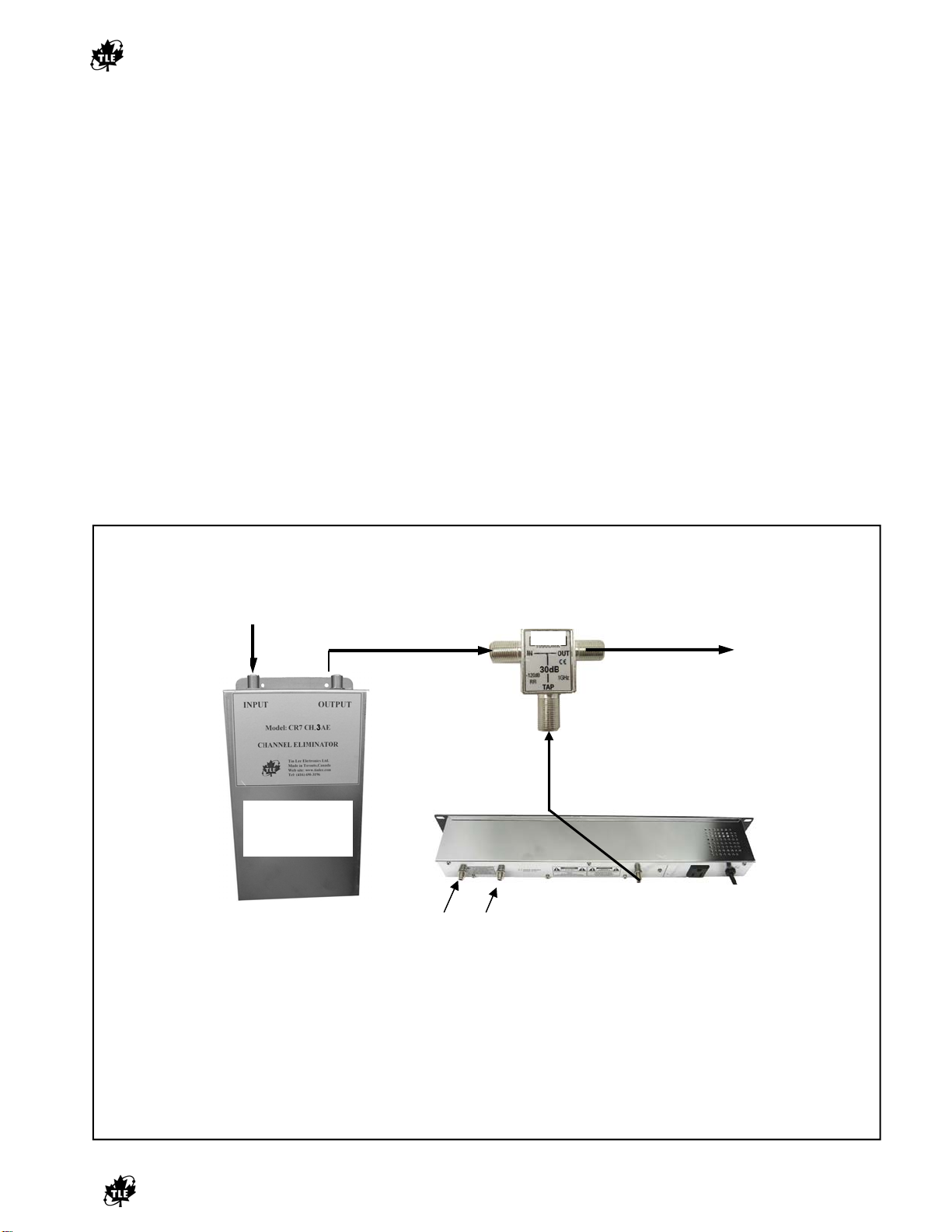
Hookup of CR7-3AE, 300VMF and DC-182-30dB (Please refer to diagram below):
1. Connect 300VMF-ch.3 RF output to TAP of DC-182R-30dB;
2. Connect Cable Signal, with CR7-3AE inline, to OUTPUT of DC-182R-30dB;
3. Combined Cable TV/ Modulator output to TV distribution system is taken from the INPUT of DC-182R-30dB;
4. Check for modulator interference on adjacent chs 2 and 4. If interference occurs, reduce the modulator output at level control -15dB.
Adjust modulator to similar level as the cable signal.
* Use Combiner with lower Tap value for modulators with lower output levels, e.g., use 10 dB tap for +20 dB modulator, or, use two-way
CR7-3AE and 300 VMF hookup with 30 dB coupler
For best results. Cable TV signal and Modulator output signal levels should be balanced. Example: If input Cable TV signal
level is +10 dBmV, set modulator output level between +40 to 45 dBmV , after combiner loss (30 dB tap) a “balanced” level
is approximately 9 dB dB.
300-VMF Modulator Ch. 3 Output
Output Level +55 dBmV
Adjust output level to 40 dBmV to “balance”
with cable TV signal
Cable TV Signal to
channel deletion filter
Cable TV system
CR7-3AE
Deletion Filter
5-1000 MHz
DC-182R-30 dB
Directional Coupler
“Reverse Coupled”
INOUT
30 dB TAP
signal level
+10dBmV
Note:
signal level
+ 9 dBmV (approx)
Tin Lee Electronic Ltd. Canada Tel.: (416) 690-3196 Fax(416) 690-0932 Email: [email protected] Website: www.tinlee.com
Video Audio
Hookup for Deletion Filter and Modulator (300VMF)
DC-182
This manual suits for next models
2
Popular Security System manuals by other brands

Easywave
Easywave RTRP02 series Operating instruction

Cooper Security
Cooper Security i-On 40 Programming reference

Viking
Viking PROXCARD Technical practice

Risco
Risco Agility 3 Quick installation guide

Milanity
Milanity Milan Vortex SLEN01 user manual

Federal Signal Corporation
Federal Signal Corporation Vision SLR Series Installation maintenance and service manual


