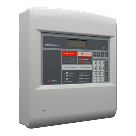
Tiras PRIME A User manual

FIRE ALARM SYSTEMS
ADDRESSABLE FIRE CONTROL PANEL
Tiras PRIME A
Operation manual
AAZCh.425521.009 OM
DSTU ISO 9001:2015
Serial number:
Firmware version:

2
Thank you for choosing
the equipment produced by Tiras-12 Ltd.
Before using the product,
please refer to this document
and save it to receive
necessary information in the future.
For complete information
and to download the documents,
use the following links:
tiras.technology
KNOWLEDGE BASE:
Operation manual
Passport
APPLICATIONS FOR PC:
aLoader
(Windows)
aLoader
(MacOS)

3
Contents
1 List of abbreviations ...................................................................................................................... 5
2 Terms and definitions ................................................................................................................... 5
3 AFAS components and their purposes........................................................................................ 6
4 General features of AFAS .............................................................................................................. 8
4.1 Restrictions in AFAS structure ............................................................................................... 8
4.2 General recommendations for the AFAS structure............................................................. 8
5 Technical features of FCP............................................................................................................ 14
6 Safety requirements.................................................................................................................... 16
7 FCP structure................................................................................................................................ 16
7.1 Description of structure ....................................................................................................... 16
7.2 Connectors............................................................................................................................. 19
7.3 Indication means of FCP....................................................................................................... 20
7.4 Controls of FCP ...................................................................................................................... 22
8 FCP operation............................................................................................................................... 25
8.1 Basic algorithm of AFAS functioning .................................................................................. 25
8.2 General features of FCP operating modes......................................................................... 25
8.3 Standby mode ....................................................................................................................... 27
8.4 Fire alarm mode.................................................................................................................... 27
8.5 Disable mode......................................................................................................................... 31
8.6 Fault warning mode.............................................................................................................. 32
8.7 Service mode ......................................................................................................................... 33
8.8 Access levels .......................................................................................................................... 33
9 Second access level ..................................................................................................................... 34
9.1 Entering the second access level menu ............................................................................. 34
9.2 [LOG] button.......................................................................................................................... 35
9.3 [USERS] button ...................................................................................................................... 36
9.4 [SYSTEM SETTINGS] button.................................................................................................. 37
9.5. [Indication test] button ....................................................................................................... 38
9.6 [DISABLING] button.............................................................................................................. 38
9.7 [POWER STATUS] button ...................................................................................................... 40
9.8 Deactivation and activation of alarm with [Alert] button................................................. 40
9.9 [Delay] button........................................................................................................................ 41
9.10 [Reset] Button ..................................................................................................................... 42
10 Third access level ....................................................................................................................... 42
10.1 Entering the third level access menu ............................................................................... 42
10.3 [ZONES] button, zone settings, verification types........................................................... 45
10.4 [DEVICES], [OUTPUTS], [INPUTS] buttons, addressable component settings ............. 52
10.5 [SMK DUST LEVELS] button................................................................................................ 63
10.6 [INSTALLER LOG] button.................................................................................................... 64
10.7 [INSTALLER] button ............................................................................................................ 64
10.8 [CONTACT INFORMATION] button ................................................................................... 64
10.9 [PASSWORD] button ........................................................................................................... 64
10.10 [SYSTEM SETTINGS] button.............................................................................................. 65
10.11 [RESET SETTINGS] button................................................................................................. 65
10.12 [ADDRESSABLE INTERFACES] button, AI settings.......................................................... 65

4
10.13 [DAY/NIGHT] mode........................................................................................................... 67
10.14 [COMMUNICATION SETTINGS] button........................................................................... 68
10.15 [EXPANSION SETTINGS] button....................................................................................... 68
10.16 [FARS SETTINGS] button................................................................................................... 69
10.17 [COMMUNICATION CHANNELS] button......................................................................... 72
10.18 [SCENARIOS] button. Scenarios setting ......................................................................... 73
11 Exploitation of AFAS................................................................................................................... 82
11.1 Installing of AFAS ................................................................................................................ 82
11.2 AFAS settings ....................................................................................................................... 85
11.3 Operation and maintenance of FCP and AFAS ................................................................ 86
12 Operating and storage conditions........................................................................................... 87
Appendix А.Calculation of battery capacity ................................................................................ 88
Appendix B. Examples of connecting devices to the FCP terminals ......................................... 90
Appendix C. Message codes sent to FARS in the Contact-ID protocol ..................................... 93
Appendix D. Message on faults..................................................................................................... 94

5
This operation manual contains technical and functional features, and instructions for
installation of the fire control panel Tiras PRIME A (further –FCP), and the rules of project
development based on it, configuration and operation of addressable fire alarm systems
Tiras PRIME A (from now on –AFAS).
The FCP meets the mandatory requirements of DSTU EN54-2 standard, it contains the
integrated power supply equipment (further –PSE), which meets the requirements of DSTU
EN54-4. When the communicator (M-GSM module) is installed, the FCP meets the
requirements of DSTU EN54-21 standard.
Personnel is allowed to operate the FCP and AFAS after on-the-job training on the rules
for the use of AFAS and the rules for the safe operation of electrical installations with voltage
up to 1000 V.
Personnel with special education in the installation of low-voltage circuits of automated
control systems and electrical circuits with a voltage of up to 1000 V and the appropriate
approval are allowed to install and set FCP and AFAS, after reading these instructions and
operating documents on the other components of AFAS, ordered by the consumer.
The requirements of DSTU-H CEN/TS 54-14: 2009 “Fire detection and fire alarm systems.
Part 14. Guidelines for the planning, design, installation, commissioning, use, and
maintenance (CEN/T 54-14: 2004, IDT) should be met.
1 List of abbreviations
1.1 The following abbreviations are used in this manual:
АІ
–addressable interface.
PSU
–power supply unit;
CIP
–control and indication of the FCP Tiras PRIME A
MCU
–microcontroller unit of FCP Tiras PRIME A
RI
–remote indicator
SI
–sound indicator;
SCI
–short circuit isolator;
PC
–personal computer;
FCP
–fire FCP Tiras PRIME A;
FARS
–Fire alarm receiving station;
ECD
–Electrical automatic Control and delay Device Tiras-1X;
ASD
–Addressable smoke detector DETECTO SMK100 (SMK110);
AMCP
–Addressable manual call point DETECTO MNL100 (MNL110);
AFAS
–Addressable fire alarm system based on Tiras PRIME A;
AHD
–Addressable heat detector DETECTO HT100 (HT110);
ACD
–Addressable combined detector DETECTO MLT110
ATS
–alarm signals transmitting system;
2 Terms and definitions
Addressable fire alarm system (AFAS) –group of components in a system of a certain
configuration, that can detect, and notify on fire and generate signals to take appropriate
measures.
Addressable Interface (AI) –physically wired connection between the AFAS and the FCP used
to transmit information on device status, transmit commands to devices, and their suppling.

6
Detector –component of the AFAS that contains at least one sensor that monitors one
physical and (or) chemical phenomenon associated with fire continuously or periodically at
short intervals and emits at least one appropriate signal to the FCP.
Siren –sound or light and sound device intended to alert people to the need to evacuate
from areas where a fire has been detected.
Zone –some defined part of the protected premises, in which one or more components
are installed and a general indication of the current state is provided for them.
Verification (dependency) –software-provided function of the FCP, which is used to
confirm the switching of a detector by checking its re-operation through automatic reset or
waiting for the operation of two detectors in the same zone.
Communicator –fire alarm and fault warning device M-GSM.
Addressable button –addressable button Detecto BTN100/110 for automatic systems
management.
Addressable device –device that is connected to the AI according to the AFAS project
(addressable detectors, modules, buttons, sirens).
Module –addressable or conventional input/output device.
Expansion line –communication line that connects several FCPs over an ethernet port
within a single AFAS.
3 AFAS components and their purposes
Table 3.1 lists the addressable devices used in AFAS projects. For detailed information
on addressable devices, refer to their operating documents. The parameters and features of
the FCP are given in section 5 of this manual.
Table 3.1 –Addressable components of AFAS
Component name
Functions, structural features
Addressable fire FCP
Tiras PRIME A
Designed to supply power to other components of a system, receive
and process the information from fire detectors, indicate the
condition of a fire alarm and fault, transfer signals of a fire alarm to
sirens, FARSs, and automatic fire extinguishing equipment.
Addressable smoke
detectors
Detecto SMK110
and Detecto SMK100
Designed to detect fires that are accompanied by appearing smoke
in small concentrations, generate and transmit fire alarm signals
to a FCP via AI. Built-in SCI.
SMK100 detector does not contain SCI and the output of the RI
control.
Addressable heat
detectors
Detecto HT110
and Detecto HT100
Designed to generate a fire alarm signal when the ambient
temperature threshold is exceeded and transmit it to a FCP via AI.
Built-in SCI.
The HT100 detector does not contain a SCI and a RI control output.
Addressable combined
detectors
Detecto MLT110
Designed to detect a smoke and/or an increase of ambient
temperature in premises, generate and transmit fire alarm signals
to a FCP via AI. Built-in SCI.
Addressable manual
call points
Detecto MNL110
and Detecto MNL100
Designed to manually generate a fire alarm signal and transmit it
to a FCP via AI.
Built-in SCI.
MNL100 manual call point does not contain SCI.

7
Table 3.1 continued
Component name
Functions, structural features
Addressable buttons
Detecto BTN110
and Detecto BTN100
Designed to manually activation of automatic systems devices. Can
be marked with functional name as required.
Built-in SCI.
BTN100 button does not contain SCI.
Addressable module
AM-Converter
Designed to connect the ECD Tiras 1X (see note 1) or the M-OUT8R
module (see note 2) to FCP through AI. Built-in SCI.
Addressable module
AM-Multi
Designed to connect non-addressable detectors to the FCP via AI,
additionally contains one input of general-purpose and one output
with line control (alert).
Built-in SCI.
Addressable module
AM-OUT2R
Designed to increase the number of relay outputs in the AFAS. It
contains 2galvanically isolated relay outputs without line control.
Built-in SCI.
Addressable module
AM-OUT1R+
Designed to increase the number of inputs and relay outputs in the
AFAS. It contains 1galvanically isolated relay output without line
control, 2universal inputs with line control and 1input for 230V
power control. Built-in SCI.
Addressable module
AM-IN4
Designed to increase the number of inputs in the AFAS. It contains
4universal inputs with line control. Built-in SCI.
Addressable module
AM-Multi+
Designed to increase the number of AIs, inputs and outputs in the
AFAS. Contains:
1) 5 universal inputs with line control (controlled parameter -
resistance);
2) 2 universal outputs with the ability to control the line (alert);
3) 2 power outputs for peripheral devices supplying (24V DC);
4) 2 slots for expansion modules;
5) built-in power supply unit 230V AC.
Built-in SCI.
Addressable module
AM-Loop
Designed to be installed in module AM-Multi+ for increasing the
number of Ais (one module AM-Loop –one loop or two radial AIs).
Built-in SCI.
Module M-OUT2R
Designed to be installed in module AM-Multi+. Contains 2 relay
outputs. Built-in SCI.
Addressable sirens
Alarmo100
Alarmo110
Designed for sound and light signals in fire alarm systems.
Built-in SCI.
The Alarmo100 siren does not contain a SCI
Notes.
1. The ECD Tiras 1X is designed to control of gas, aerosol or power extinguishment.
2. The M-OUT8R module is designed to increase the number of relay outputs in fire
alarm systems, it contains 8 relays.
3.2 An M-GSM module may be installed in the FCP. It generates fire alarm notifications
and fault signals and sends them to FARS via the GSM network (GPRS channel).

8
4 General features of AFAS
4.1 Restrictions in AFAS structure
4.1.1 The following limitations should be taken into account when developing a project
with a single FCP:
1) number of components in AFAS up to 4000;
2) number of AI in AFAS not more then 128 (including AI connected to FCP and AI
connected to AM-Multi+ via M-Loop);
3) maximum 250 addressable components can be connected to each AI;
4) maximum 250 addressable components can be connected to each AM-Multi+ (if
installed 1modules M-Loop up to 250 components in its AI, if installed 2 modules M-Loop up
to 125 components in its AI);
5) up to 1000 outputs of any type (with or without control). This number includes
outputs of the FCP, modules outputs and addressable sirens;
6) up to 1000 inputs (including all FCP and modules inputs);
7) not more than 1000 zones can be programmed;
8) not more than 128 groups can be created;
9) not more than 100 outputs of any type can be assigned to one zone ore one group
(including addressable sirens);
10) not more than 2 ECDs can be assigned to one zone;
11) not more than 32 ECDs can be connected to AFAS;
12) recommended length of the AI between the connection terminals in the FCP and
any addressable component in any AI configuration (loop or radial) have not exceed 2000 m;
13) the total current consumption from the AIs of all connected addressable
components in all operation modes of the FCP should not exceed 80 mA.
4.1.2 If the AFAS contains several FCPs, the restrictions set out in paragraph 4.1.1 are
applied to each of the FCPs. Thus, the total indicators of AFAS increase proportionally. One
AFAS may include not more than four interconnected FCPs.
4.2 General recommendations for the AFAS structure
4.2.1 In the general case, an AFAS consists of:
1) one or more FCPs;
2) addressable components listed in Table. 3.1, their number is determined by the
project taking into account the restrictions of sections 4.1, and 4.2;
3) conventional sirens (connection is shown in Fig. B.4) and addressable sirens;
4) power supply units;
5) non-addressable devices (ECD);
6) actuators (connected to the relay outputs of modules AM-OUT1R+, AM-OUT2R and/or
M-OUT8R).
7) M-GSM module. If necessary, messages are transmitted f to the FARS (the module is
installed in the FCP).
8) conventional detectors and/or buttons connected to universal inputs of addressable
modules (AM-OUT1R+, AM-IN4, AM-Multi, AM-Multi+).
Addressable conventional components of AFAS should be used according to their
manuals.

9
Note. Initialization time of the AFAS after FCP power on is depending on number of
address components connected to one FCP. Approximately one address component is
initialized for 1 s.
The configuration of the AFAS zones, components and cables installing, protection of
the components and cable lines of the AFAS from external influences should be complied
with current fire alarm systems and building standards.
The guides for connection of several FCPs in one AFAS are given in points 4.2.10 –4.2.12.
The following recommendations apply to AFAS based on both one and several FCPs.
4.2.2 Addressable components are connected to AI, which are both communication
lines and power lines. FCP controls AIs connected to MCU and to M-Loop. The common
scheme of possible connections in AI is shown in fig. 4.2.1.
FCP
L1
L2
L3
L4
ASD
ASD
ASD
ASD
AHD
ASD
ASD
AHD
ASD
AHD
AHD
ASD
AHD
ASD
ASD
ASD
ASD
ASD
AMCP
M-OUT8R
АМ-
Converter
АМ-
Converter
АМ-Multi+
SD
HD
АМ-OUT2R
ECD
АМ-Multi
M-Loop
L1
L2
M-Loop
L1
L2
АМ-
OUT1R+
ASD
АМ-IN4
АМ-Multi+
M-OUT2R
M-OUT2R
Figure 4.2.1 –Connection scheme for connecting addressable components to AI
General rules for connecting AIs to the FCP:
1) one end of the loop AI No.1 is connected to terminals L1-G1, the other one –to the
terminals L2-G2. Accordingly, one end of the loop AI No.2 is connected to terminals L3-G3,
the other one to terminals L4-G4;
2) radial AI is connected to the pairs of terminals: L1-G1, L2-G2, L3-G3, L4-G4.
Addressable components in one radial AI should be registered in one zone so that a single
fault in such AI does not affect other zones;

10
3) in exceptional cases it is allowed to make radial branches from the loop AI: both from
the cable and the place of addressable component connection. In this case, the reliability of
the AFAS is reduced, because in case of a open or short circuit of the radial line (branch)
communication with the addressable components located between the end of the radial line
and the open will be lost. Also, it is more time-consuming to find the place of open or short
circuit in a loop AI with branches.
Modules M-Loop installed in modules AM-Multi+ are used to increase number of AIs.
Additional AIs are connected to terminals L1-G1, L2-G2 of M-Loop module. Another module
AM-Multi+ can be connected to this M-Loop, but it can be used only as input/output
expansion module (without possibility of M-Loop installation).
4.2.3 To reduce the current consumption of AFAS in the standby mode in the AI is
allowed to install detectors without CSIs (Table 3.1). In this case, there are the following
restrictions:
1) not more than 10 detectors without SCI can be installed in a row;
2) groups of detectors without SCI, installed in adjacent zones, should be separated by
at least one addressable component with SCI.
4.2.4 Two-wired conventional (non-addressable) detectors can be connected to the AI
via the AM-Multi module. If there is a need to use explosion-proof non-addressable detectors
in the AFAS project, they are connected to the AM-Multi module via the MBI-2 (24V) barrier
spark protection module, which meets the requirements of explosion protection when using
ExibII-marked non-addressable detectors.
Warning! The GND terminals of the AM-Multi modules should not be connected to the
LGND terminal of the FCP by any lines, otherwise, the automatic AI testing process will be
disrupted.
4.2.5 If it is planned to use addressable sirens, it is necessary to take into account that
they have a significant current consumption from the AI in the fire alarm mode and it is
necessary to calculate the load on the AI in such a way as to prevent overloading of the AI
during their operation.
4.2.6 If ECD is assigned to any of AFAS zones and it is activated from FCP, not less than
two addressable components (detectors or AM-Multi modules) should be installed in this
zone, and the condition of ECD activation is the transition of two addressable components in
fire alarm mode.
4.2.7 Any sensors can be connected to the parametric inputs of the AM-IN4, AM-OUT1R+
and AM-Multi+ modules, but they should not be used as fire detectors, as these inputs have
not fire alarm mode.
4.2.8 When using the REL relay contacts of the AM-OUT1R+ module, it is need to take in
account that they are reset only after resetting from the front panel of the FCP or after re-
registering the module, which occurs after powered on the AI.
Warning! The activated relay output of the AM-OUT1R+ module does not return to its
original state when the AI is powered off.
4.2.9 External PSUs in the AFAS can be used for:
1) power supply for devices in both AI, if own power supply outputs of peripheral
devices of FCP are already involved or if the capacity of own batteries of FCP is not enough
for power supply of AFAS during the normalized time of AFAS staying in a fire alarm mode;
2) power supply of detectors and parametric loops with non-addressable detectors
connected to AM-Multi, if necessary;

11
3) power supply AM-OUT2R, if there is no technical possibility to use own power outputs
of peripheral devices of the FCP;
4) power supply of remote devices of optical signaling devices (RI), connected to
detectors, if necessary;
5) power supply of non-addressable devices of AFAS (if used).
PSUs used in AFAS should provide the current consumption of electrical circuits,
calculated according to the project, as well as charging the required number of batteries,
determined by the method from the Annex A of this manual. When using external PSUs in
AFAS it is necessary to avoid drawing long lines from them to addressable components and
non-addressable devices.
4.2.10 If it is necessary, RI can be connected to the detectors. Examples of connection
schemes are shown in Fig. 4.2.2.
PSU
1
2
4
3
1
2
4
3
ASD/
AHD
+24V GND
1
2
4
3
ASD/
AHD
LPOW
Rlim
Rlim
Rlim
3
Rlim
3
1
2
4
3
RI
RI
RI
RI
G1
L1
G2
L2
G3
L3
G4
L4
LGND
MCU
GND
+24V
GND
B
A
ASD/
AHD
ASD/
AHD
Figure 4.2.2 - Examples of RI connection
The following features should be considered:
1) RI can be connected only to ASD or AHD with built-in SCI;
2) it is allowed to connect RI to detectors in separate AI, but it is necessary to set limits
on the number of simultaneous fire alarm indications (10.13.1) N in these AIs:
N = (100 mA) / IRI.
For example, no more than 10 simultaneous indications, provided that a consumption
current of RI during the fire alarm indication is 10 mA;
3) consumption current of the RI should be selected in accordance with their datasheets

12
and should provide a clear visualization of the fire alarm. This current is provided by means
of Rlim(Fig. 4.2.2): Rlim = (UPS - 1V) / IRI.
4.2.11 Type of cable for AFAS installation depends on the needs of the project. It is
allowed to use solid and stranded cables.
It is recommended to use cables with a cross-section of 0.75 to 2.5 mm2for AI. In AIs of
short length (up to 1000 m) it is allowed to use cables with a cross-section of at least 0.5 mm2,
but if the condition 4.2.8 is met.
It is recommended to use cables with a cross-section of at least 0.75 mm2to connect
external PSUs. If long power supply lines cannot be avoided, it is necessary to calculate the
voltage drop across the wires for them at the maximum current consumption of the
connected devices to determine the risk of performance loss for these devices.
For other lines it is recommended to use cables with a cross-section not less than
0,5 mm2.
4.2.12 For each AI it is required to calculate:
1) the total resistance of wires in the cable, which is used in AI;
2) the total resistance of all SCIs of addressable components that are going to be
installed in this AI (see operational documents of addressable components);
3) the total resistance of the contact connections between the detectors and their bases,
which is on average equal to the resistance of a closed SCI for one detector.
The sum of the obtained resistance values should not exceed the total resistance of the
AI, specified in table. 5.1.
4.2.13 The load current for outputs of the AFAS components (FCP, AM-Multi, AM-OUT2R,
AM-Multi+, AM-OUT1R+) should be calculated so that it does not exceed the values specified
in the datasheets for these components.
4.2.14 If several FCPs are included in the AFAS, they are connected according to the
scheme shown in Fig. 4.2.3.
ETH-L
ETH-R
FCP No. 1
ETH-L
ETH-R
FCP No. 2
ETH-L
ETH-R
FCP No. 3
ETH-L
ETH-R
FCP No. 4
ETH-L, ETH-R –Ethernet sockets (see 7.2.2, fig.7.3).
Figure 4.2.3 –Example of the connection scheme between FCP within AFAS

13
Arbitrary variants of ETH-R and ETH-L port connections of different FCPs are allowed
within the AFAS, but “ring”topology (main and reserve connection) is recommended.
Warning! FCPs should be provided the same version of firmware.
4.2.15 The FCPs should be connected via network four-pair cables Category 5 or higher
with a length of not more than 100 m. If it is need to be connected at a greater distance from
each other, FO cables and additional network devices (e.g., mediaconverters) should be used.
The data transfer rate between the FCP is 10 Mbit/s. Network devices should support Auto-
negotiation and AutoMDI-X technologies (see 11.1.13).
4.2.16 The M-GSM module may be installed only in one FCP of AFAS.

14
5 Technical features of FCP
5.1 General features
5.1.1 FCP provides:
1) 6 outputs: AL (Fire), FT (Fault), OUT1 –OUT4 (notification with the possibility of
programming functions);
2) 2 controlled power supply outputs for peripheral devices 24 V;
3) 2 universal inputs without line status control IN1, IN2 (may be used for external PSU
status control);
4) 2 separate AIs with open and short circuit control;
5) separate input of AI power supply with voltage from 20 to 30 V –power supply from
a third-party PSU is possible;
6) 2 Ethernet interfaces 10 Mb/s;
7) service interface RS485;
8) USB interface for programming and configuration;
9) interface for connecting a communicator (M-GSM module);
9) integrated PSU;
10) built-in charger (with battery capacity control and voltage control on each battery);
11) backup power supply –two sealed lead-acid batteries (Table 5.1);
12) non-volatile clock;
13) event log with 10,000 messages.
5.2 Main technical features
5.2.1 The main technical features of the FCP are given in table 5.1.
Table 5.1 –Main technical features of FCP l
Feature
Value
Primary power source: AC mains, V
187-242
Primary power source: AC mains frequency, Hz
50±1
Maximum current consumption from the primary power source in all
modes, A
0,27
Maximum power consumption from the primary power source, VA
60
Backup power source: nominal voltage of a single battery, V
12
Backup power source: capacity of a single battery, A*h
7
Maximum battery charging current, mA
500
The permissible internal total resistance of both batteries and their
connection circuits, Rimax, Ohm, not more than
1,0
The output voltage of integrated PS, V
21,0 –29,5
Maximum current consumption from the integrated PS in all modes,
Imin1, A
0,05
Maximum long-term current consumption from the integrated PS
with the maximum loadings, Imax_a2, A
1,1
Maximum long-term load current of "+ 24V" outputs (each), mA
400
Maximum current consumption by AI LPOW power input, mA
140
Dimensions (WxHxD), mm
350 × 365 × 100
Net weight (without battery), kg
4
Mean time to failures, h., not less than
40000
Average lifetime, years, not less than
10
Enclosure protection degree (ІЕС 60529)
ІР30

15
Table 5.1 continuing
Inputs and outputs
Maximum number of zones
1000
Maximum number of detectors in a zone, pcs
32
Voltage at AI terminals in all modes, V
24 –25
Maximum current of AI, mA
80
Minimum leakage resistance in AI (between each wire and
ground), kOhm
50
Sum of resistances of AI wires and the resistance of the short-
circuit isolators, Ohm, not more than
125
Maximum output voltage at IN1, IN2 inputs, V
3
Maximum output current of IN1, IN2 inputs, mA
0,1
Maximum switching current of FT, AL outputs, mA
400
Maximum switching current of OUT1-OUT4 outputs, mA
800
Maximum switching voltage of FT, AL, OUT1-OUT4 outputs, V
30
Resistance of the terminal resistor for the AL output, kOhm
6,8 –30
Maximum short-circuit resistance of the AL output at the GND
terminal, kOhm
1,4
Resistance of the terminal resistor for OUT1-OUT4 outputs, at the
supply voltage of 20 - 29,5 V on U12, U34 inputs, kOhm
1,3 –8,2
Open circuit resistance of the OUT1-OUT4 output line, not less
than, kOhm
> 8,2
Short circuit resistance of OUT1-OUT4 outputs on the GND
terminal, kOhm
< 1,3
Voltage at the outputs + 24V, V
21,0 –29,5
Maximum jutput current of each output + 24V, A
0,4
Fuses
AC network, A
3.15
"+24V" outputs, A
2 × 0,5, self-restoring
OUT1-OUT4 outputs, A
4 × 1,0 self-restoring
Communicator power supply, A
0,2, self-restoring
Time features
Maximum detection time of alarm (fault) in zones, s
10
Maximum fault detection time (except zones), s
100
Maximum time to determine the battery capacity (low capacity),
min
15
Maximum time to determine the battery absence, min
2
Wire cross-section, permissible for clamping in terminals, mm2, (for
stranded wires)
0,22 - 2,5
Notes.
1. According to DSTU EN54-4, without AI consumption and with automatically switched off display.
2. According to DSTU EN54-4, with AI consumption, with the display, switched on, power supply of
peripheral devices from outputs "+ 24V".
5.3 Technical features of a GSM cellular radio module, which is equipped with M-GSM,
are shown in Table 5.2.

16
Table 5.2 –Technical features of a GSM cellular radio module
Feature
GSM-channel
900
1800
Transmitter frequency range, MHz
888 –915
1710 –1785
Receiver frequency range, MHz
933 –960
1805 –1880
Transmitter output power, W, not more than
2
1
5.4 The features of the communication channels provided by the FCP via the M-GSM
module are shown in Table 5.3.
Table 5.3 –Communication channel features
Parameter name according to EN 50136-1
Type 1
channel
Type 2
channel
Transmission delay time
D4=10 s
Maximum transmission delay time
М4 = 20 s
М3 = 60 s
Reporting time, not more than
Т5 = 90 s
Т2 = 25 h
Availability class
А4
Substitution protection
S0 (no)
Information protection
І0 (no)
6 Safety requirements
6.1 For installing and operating with FCP, service personnel should be guided by the
Rules of technical operation of consumers’ electrical installations and Safety rules of the
operation of consumers’ electrical installations.
6.2 Mounting, demounting, and maintaining of a FCP should be carried out only with
the supply voltage switched off on FCP.
6.3 Fire safety rules should keep when carrying out any works.
7 FCP structure
7.1 Description of structure
7.1.1 The FCP housing consists of a base, a cover, and a front panel and provides a
protection degree of IP30 (fig. 7.1) (the base is shown in fig. 7.2).
To access the terminals of a FCP, battery, real-time clock battery, remove a cover:
1) unscrew two screws in the lower part of the housing (Fig. 7.1);
2) pull the lower edge of the cover, lifting it, remove it from the protrusions on the upper
edge of the base.
Replace a cover in reverse order.
7.1.2 There are holes for wires and cables and holes for fixing a FCP on a vertical plane
on its base behind a front panel and in the upper part of a base (Fig. 7.2). All cable holes are
pre-sealed with plugs. When inserting cables into a housing, open the plugs in the chosen
area. If cables are inserted through the top row of holes, the used holes should be sealed in
order to maintain the protection degree of the housing shell.
All the connections should be done with the power supply of FCP is
switched off.

17
Figure 7.1 –FCP view (front side)
PSU is attached to a front panel on a base wall. There are slots to install two batteries
at the bottom of a base.
The front panel is fixed on a base with four clamps (Fig. 7.2), which allow you to turn
the front panel up if necessary. The lower locks and the right upper latch are open, the left
upper lock is closed to prevent the front panel from falling out of a base when turning.
Additionally, a front panel is attached to a base with two screws.
To remove a front panel from a base, do the following:
1) unscrew two mounting screws from a base (Fig. 7.2);
2) pull a lower edge of a panel from lower locks (after that you can, if necessary, turn a
front panel without removing it from a base);
3) pull one of the upper corners of a panel from the open lock;
4) remove the second corner of a panel from a closed lock.
Replace a front panel in reverse order.
Front
panel
Cover
Touch screen
Keypad
Screws for cover fixing

18
Figure 7.2 –FCP view with a front panel removed
CIU and MCU are fixed to the front panel with screws. MCU and CIU are interconnected
through an adapter.
7.1.3 The display is attached to the CIU and connected to the sockets XS2, XS3 of MCU by
loop cables routed through the hole in the CIU board (Fig. 7.3).
On the MCU board, there is a hole for connecting and fastening an M-GSM module.
Terminals for
connecting АІ
USB-port
Locks
Locks
Slots for batteries
Screws for fixing
front panel
Holes for cables
(sealed)
Inputs and outputs
terminals
Housing
base

19
1 –CIU;
2 –MCU;
3 –touch display;
4 –connection cables of the touch display;
5 –XS5 socket of the real-time clock battery;
6 –XS1 socket for M-GSM module connection (communicator);
7 –XP1 plug for connecting cables from PSU;
8 –location of the BOOT button;
9 –location of the START button.
10 –sockets of Ethernet ports X8, X9 (ETH-L, ETH-R).
,
Figure 7.3 - View of FCP front panel from the backside and in section
7.2 Connectors
7.2.1 PSU has a connector for connecting a 230 V, 50 Hz primary power line. A PSU output
cable is connected to the corresponding plug on the MCU.
7.2.2 The following connectors (Figures 7.2, 7.3) are located on the MCU
1) XS4 –USB-port for MCU programming;
2) XP1 –plug, power input;
3) XS1 –socket for connecting communicator;
4) XP2 –JTAG port, service;
5) X8, X9 –Ethernet port sockets (ETH-R, ETH-L);
6) X10 –plug for connecting to CIU;
7) XP3 –plug for programming; a battery control microcontroller
8) XS5 –socket for real-time clock battery;
9) terminals LPOW, LGND to connect the AI power line;
10) terminals L1, G1, L2, G2 to connect the AI1 loop (LINE1);
11) terminals L3, G3, L4, G4 to connect the AI2 loop (LINE2);
12) terminals AL, GND, FT to connect circuits for fire alarm and fault signals transmission;
7
6
5
3
1
2
4
98 4 1 2 10

20
13) terminals OUT1 - OUT4 –outputs of the FCP with programmable functions;
14) terminals IN1, IN2 –universal inputs for connecting relay groups of contacts;
15) terminals U12, U34 - for power supply for pairs of outputs OUT1 - OUT2 and OUT3 -
OUT4;
16) terminals + 24V, GND –24V DC outputs;
17) terminals B, A, GND –RS485 interface, half-duplex, service.
7.3 Indication means of FCP
7.3.1 The indication means include LED indicators on a front panel of FCP, a display
showing messages in accordance with the FCP operation mode, and an audible indicator
inside a FCP.
The purpose and operation of LED indicators, as well as messages on a display, meet the
requirements of DSTU EN 54-2 on the operation modes of the FCP (section 7).
The audible indicator is activated when a FCP enters the fire alarm mode or the fault
warning mode.
7.3.2 The location of the indicators on the front panel of FCP is shown in Figure 7.4, and
their purpose is described in table 7.1.
Figure 7.4 –Location of buttons and indicators on the FCP front
panel
Table of contents
Other Tiras Control Panel manuals
Popular Control Panel manuals by other brands
Arzel
Arzel Zone Control 200 Series Installation & operation instructions

urmet domus
urmet domus 1083/12 Configuration guide
Siemens
Siemens SIMATIC S7-300 CPU Data: CPU 315-T-2 DP manual
PEAKnx
PEAKnx Controlmicro Getting started
STG-BEIKIRCH
STG-BEIKIRCH TRZ Basic 8HM Technical information and operating instruction

ECI
ECI LiteWizard installation manual
Zonefirst
Zonefirst H32P Uni-Zone Installation and operating instructions for the installer
Siemens
Siemens SIMATIC HMI series Getting started
GE
GE SIMON XT instruction manual
Motorline professional
Motorline professional MPXR92MSWBE User& installer's manual
Clearfield
Clearfield FieldSmart FxMP installation manual
AMX
AMX AutoPatch CP-15 quick start guide
