STG-BEIKIRCH TRZ Basic 8HM Manual

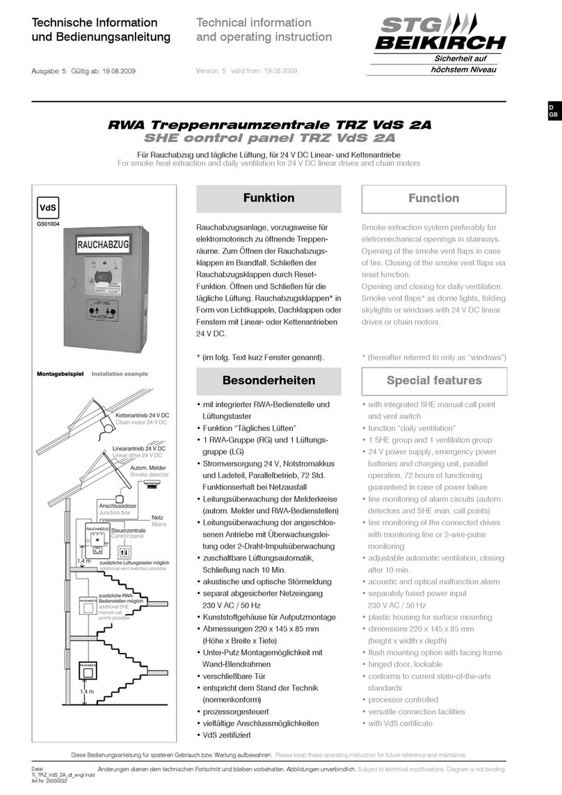
Besonderheiten Features
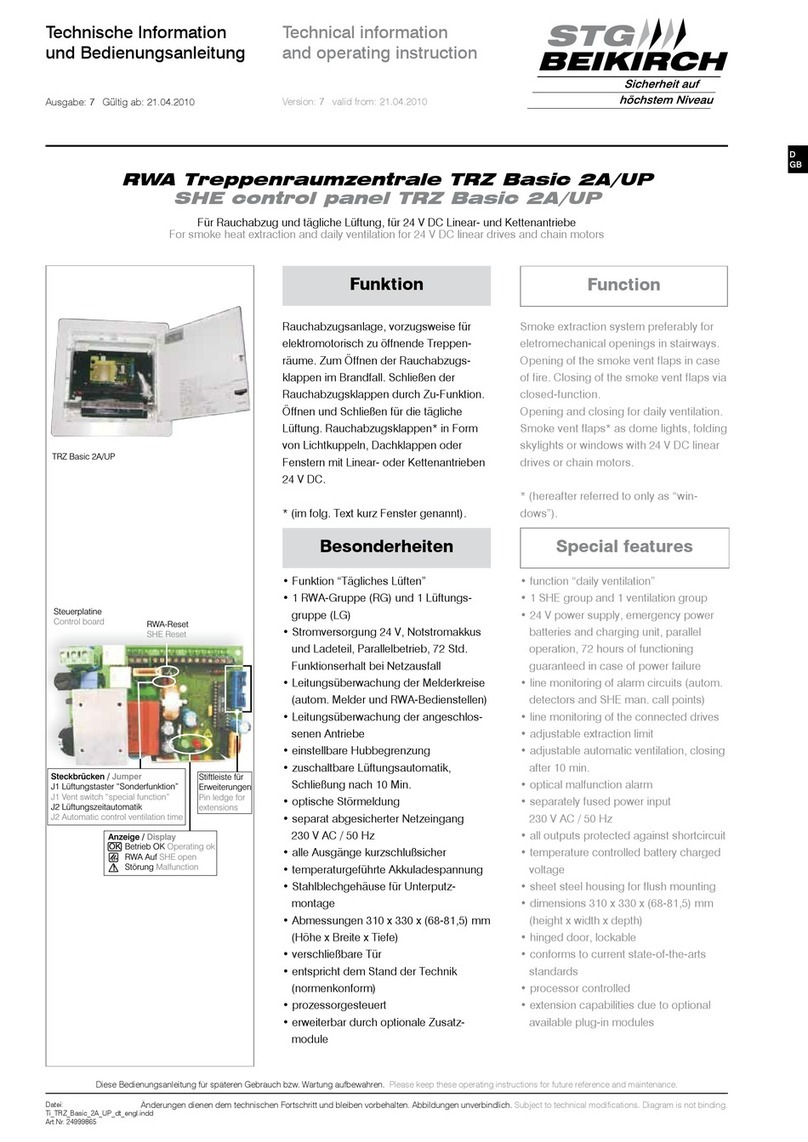
Treppenraumzentrale TRZ Basic 8HM
Control panel TRZ Basic 8HM
Funktion Function
Haftmagnetenzentrale für die dauerhafte
Bestromung von 24 V DC Haftmagneten
bis zu 0,7 A.
Die Haftmagneten werden im Brandfall
stromlos geschaltet.
Rauchabzug mittels Gasdruckfedern und
Zuhaltung über Elektro-Magnet-
Verriegelung.
Türfeststellanlage mittels Haftmagnet.
Magnetic clamps control panel for a
continuous power supply to 24 V DC
electromagnetic clamps up to 0.7 A.
In case of fire, electric current to the
electromagnetic clamps will be cut off.
She control panel using gas springs in
connection with electromagnetic locking.
As magnetic door clamp using electro-
magnetic clamp.
• 1 RWA-Gruppe (RG)
• Stromversorgung 24 V, Notstromakkus
und Ladeteil, Parallelbetrieb, 1 Std.
Funktionserhalt bei Netzausfall
• Leitungsüberwachung der Melderkreise
(autom. Melder und RWA-Bedienstellen)
• Leitungsüberwachung der angeschlos-
senen Haftmagneten
• separat abgesicherter Netzeingang
• Kunststoffgehäuse für Aufputzmontage
• Abmessungen 220 x 145 x 85 mm
• Unter-Putz Montagemöglichkeit mit
Wand-Blendrahmen
• verschließbare Tür
• entspricht dem Stand der Technik
(normenkonform)
• prozessorgesteuert
• vielfältige Anschlussmöglichkeiten
230VAC/50Hz
(Höhe x Breite x Tiefe)
mit Überwach-
ungsleitung
• optische Störmeldung
• 1 SHE group
• 24 V power supply, emergency power
batteries and charging unit, parallel
operation, 1
• line monitoring of alarm circuits (autom.
detectors and SHE man. call points)
• line monitoring of the connected
electromagnetic clamp with monitoring
line
• optical malfunction alarm
• separately fused power input 230 V AC /
50 Hz
• plastic housing for surface mounting
• dimensions 220 x 145 x 85 mm
(height x width x depth)
• flush mounting option with facing frame
• hinged door, lockable
• conforms to current state-of-the-arts
standards
• processor controlled
• versatile connection facilities
hours of functioning
guaranteed in case of power failure
Zum Anschluss von 24 V DC Haftmagneten
To connect 24 V DC electromagnetic clamps
Diese Bedienungsanleitung für späteren Gebrauch bzw. Wartung aufbewahren. Please keep these operating instructions for future reference and maintenance.
Änderungen dienen dem technischen Fortschritt und bleiben vorbehalten. Abbildungen unverbindlich. Subject to technical modifications. Diagram is not binding.
D
GB
Technische Information
und Bedienungsanleitung
Technical information
and operating instruction
Ausgabe: 5 Gültig ab: 19.04.2010 Version: 5 valid from: 19.04.2010
Stiftleiste für
Erweiterungen
Pin ledge for
extensions
RWA-Reset / SHE Reset
Steuerplatine / control board
keine Funktion
no function
Anzeige /
Betrieb OK
RWA Auf
Störung
display
operating ok
SHE open
malfunction
OK
!
Datei:
Ti_TRZ_Basic_8HM_dt_engl.cdr
Art.Nr. 24999666
Sicherheit auf
höchstem Niveau
STG
BEIKIRCH

Sicherheitshinweise
Vorsicht / Achtung / Warnung
Gefahr für Personen durch elektrischen Strom
Nichtbeachtung führt zur Zerstörung Gefährdung
für Material durch falsche Handhabung
Gefährdung für Personen durch Gefahren aus
dem Gerätebetrieb. Quetsch- und Klemmgefahr
INFO
Warnung 230 V AC
Gefährliche Spannung. Kann Tod, schwere Körperverletzung oder
erheblichen Sachschaden verursachen. Trennen Sie das Gerät
allpolig von der Versorgungsspannung bevor Sie es öffnen,
montieren oder den Aufbau verändern. VDE 0100 für 230 V
Netzanschluss beachten.
Sicherheitshinweise, die Sie beachten müssen,
werden
unbedingt
durch besondere Zeichen hervorgehoben
Caution / Attention / Warning
Danger to persons due to electricity
Non-observance leads to destruction
Danger to material due to incorrect handling
Danger to persons due to risks arising from the
operation of the equipment. Danger of crushing/trapping
INFO
Safety instructions
2
Warning 230 V AC
Dangerous voltage. Can cause death, serious injury or
considerable material damage. Disconnect the equipment from the
power supply at all poles before opening, assembling or carrying
out any structural alterations. Observe VDE 0100 for
230 V power connection.
Operating instructions
for professional assembly, installation and appropriate maintenance by
trained, qualified and safety-conscious electricians and/or skilled staff with
knowledge of electrical equipment installation.
It would be beyond the scope of these safety instructions to list all the valid
regulations and guidelines.
Always make sure that your system corresponds to the valid regulations. Pay
particular attention to: the aperture cross-section of the window, the opening
time and opening speed, the temperature resistance of the cables and
equipment, cross-sections of the cables in relation to the cable lengths and
power consumption.
Read and observe the information contained in these operating instructions
and respect the order of procedure stated therein.
Please keep these operating instructions for future reference and
maintenance. Reliable operation and the prevention of damage and risks are
only granted if the equipment is assembled carefully and the settings are
carried out according to these instructions and to the operating instructions
of the drives.
Required mounting material is to be adapted to the
frame and the corresponding load and is to be completed, if necessary. Any
supplied mounting material is only part of the required amount.
If the equipment is employed in smoke heat extraction systems (in short
SHE), they must be checked, serviced and, if required, repaired at least
once per year. This is also recommended for pure ventilation systems.
Free the equipment from any contamination. Check the tightness of fixing
and clamping screws. Test the equipment by trial run.
The gear system is maintenance free. Defective equipment must only be
repaired in our factory. Only original spare parts are to be used.
The readiness for operation has to be checked regularly. For this purpose a
service contract is recommended. All batteries provided with the SHE control
panel need to be regularly checked as part of the maintenance programme
and have to be replaced after their specified service life (approx. 4 years).
Please observe the legal requirements when disposing of hazardous
material - e.g. batteries.
and electrical connections only to be done by a qualified
electrician. Power supply leads 230 V AC to be fused separately by the
customer. Keep power supply leads sheathed until the mains terminal.
DIN and VDE regulations to be observed for the installation: VDE 0100
Setting up of high voltage installations up to 1000 V. VDE 0815 Installation
cables and wires. VDE 0833 Alarm systems for fire, break-in and burglary.
to be agreed with local inspection authorities, power utilities, fire
protection authority and the professional associations.
All low voltage cables (24 V DC) to be installed separately from high voltage
cables. Flexible cables must not be plastered in. Provide tension relief for
freely suspended cables. The cables must be installed in such a way that
they cannot be sheared off, twisted or bent off during operation. Junction
boxes must be accessible for maintenance work. Adhere to the type of
cables, cable lengths and cross-sections as stated in the technical
information.
Maintenance works
Routing of cables
Cable types
Bedienungsanleitung
Wartungsarbeiten
Leitungsverlegung
Kabeltypen
für die fachgerechte Montage, Installation und angemessene Wartung durch
den geschulten, sachkundigen und sicherheitsbewussten Elektro-Installateur
und / oder Fachpersonal mit Kenntnissen der elektrischen Geräteinstallation.
Lesen und Beachten Sie die Angaben in dieser Bedienungsanleitung und
halten Sie die vorgegebene Reihenfolge ein.
Diese Bedienungsanleitung für späteren Gebrauch / Wartung aufbewahren.
Ein zuverlässiger Betrieb und ein Vermeiden von Schäden und Gefahren ist
nur bei sorgfältiger Montage und Einstellung nach dieser Anleitung gegeben.
Bitte beachten Sie genau die Anschlussbelegung, die minimalen und
maximalen Leistungsdaten (siehe technischen Daten) und die
Installationshinweise.
Werden die Geräte in Rauch- und Wärmeabzugsanlagen (kurz RWA)
eingesetzt, müssen sie mindestens einmal jährlich geprüft, gewartet und ggf.
instand gesetzt werden. Bei reinen Lüftungsanlagen ist dies auch zu
empfehlen.
Die Geräte von Verunreinigungen befreien. Befestigungs- und Klemm-
schrauben auf festen Sitz prüfen. Die Geräte durch Probelauf testen. Das
Motorgetriebe ist wartungsfrei. Defekte Geräte dürfen nur in unserem Werk
instand gesetzt werden. Es sind nur Original-Ersatzteile einzusetzen. Die
Betriebsbereitschaft ist regelmäßig zu prüfen. Ein Wartungsvertrag ist
empfehlenswert. Alle serienmäßig mit der RWA-Steuerzentrale gelieferten
Akkus bedürfen einer regelmäßigen Kontrolle im Rahmen der Wartung und
sind nach der vorgeschriebenen Betriebszeit (ca. 4 Jahre) auszutauschen.
Bei der Entsorgung der verwendeten Gefahrstoffe - z.B. Akkus - Gesetze
beachten.
und elektrischer Anschluss nur durch zugelassene
Elektrofirma. Netzzuleitungen 230 V AC separat bauseits absichern.
Netzzuleitungen bis an die Netzklemme ummantelt lassen.
Bei der Installation DIN- und VDE-Vorschriften beachten, VDE 0100 Errichten
von Starkstromanlagen bis 1000 V, VDE 0815 Installationskabel und
-leitungen, VDE 0833 Gefahrenmeldeanlagen für Brand, Einbruch und
Überfall.
ggf. mit den örtlichen Abnahmebehörden, Energieversorgungs-
unternehmen, Brandschutzbehörden oder Berufsgenossenschaften
festlegen. Alle Kleinspannungsleitungen (24 V DC) getrennt von
Starkstromleitungen verlegen. Flexible Leitungen dürfen nicht eingeputzt
werden. Frei hängende Leitungen mit Zugentlastung versehen. Die
Leitungen müssen so verlegt sein, dass sie im Betrieb weder abgeschert,
verdreht noch abgeknickt werden. Abzweigdosen müssen für Wartungs-
arbeiten zugänglich sein. Die Kabelarten, -längen und -querschnitte gemäß
den technischen Angaben ausführen.
Es würde den Rahmen dieser Bedienungsanleitung sprengen, alle gültigen
Bestimmungen und Richtlinien aufzulisten.
Prüfen Sie immer, ob Ihre Anlage den gültigen Bestimmungen entspricht.
Besondere Beachtung finden dabei: Öffnungsquerschnitt des Fensters,
Öffnungszeit und Öffnungsgeschwindigkeit, Temperaturbeständigkeit von
Kabel und Geräten. Benötigtes Befestigungsmaterial ist mit dem Baukörper
und der entsprechenden Belastung abzustimmen und, wenn nötig, zu
ergänzen. Ein eventuell mitgeliefertes Befestigungsmaterial entspricht nur
einem Teil der Erfordernisse.
Please observe the following safety instructions which
are emphasized by special symbols
3
Vor jeder Wartungsarbeit oder Veränderung des Aufbaus sind
die Netzspannung und Akkus allpolig abzuklemmen. Gegen
unbeabsichtigtes Wiedereinschalten ist die Anlage abzusichern.
Elektrische Steuerungen müssen stromlos sein, bevor Sie Teile entnehmen
oder dazusetzen (Netzspannung und Akkus abklemmen).
und jeder Veränderung der Anlage alle Funktionen
durch Probelauf überprüfen
: Die Haftmagnete nur mit Steuerungen vom gleichen
Hersteller betreiben. Bei Verwendung von Fremdfabrikaten keine
Haftung, Garantie- und Serviceleistungen. Die Montage und
Installation muss sachgemäß, sicherheitsbewusst und nach Angaben der
Bedienungsanleitung erfolgen. Werden Ersatzteile, Ausbauteile oder
Erweiterungen benötigt bzw. gewünscht, ausschließlich Original-Ersatzteile
verwenden.
Die Geräte sind gemäß der europäischen Richtlinien geprüft und hergestellt.
Eine entsprechende Herstellererklärung liegt vor. Sie dürfen die Geräte nur
dann betreiben, wenn für das Gesamtsystem eine Konformitätserklärung
vorliegt.
Nach der Installation
Achtung
Herstellererklärung
.
Achtung! Die Haftmagnete und Bedienstellen niemals an 230 V
anschließen! Sie sind für 24 V gebaut! Lebensgefahr!
The supply voltage the batteries are to be disconnected at
all poles before maintenance work or structural alterations. The
system must be protected against unintentional re-starting.
Electrical controls must be voltage free before extension modules are taken
off or added (disconnect mains voltage batteries).
and any changes to the system check all functions by a trial
run.
Warning! Never connect the electromagnetic clampand call
points to 230 V! They are built for 24 V! Risk of death
: The control must only be operated with
electromagneic clamp made by the same manufacturer. No
liability will be accepted and no guarantee nor service is granted
if products of outside manufacturers are used. Assembly and installation
must be carried out properly, according to the information of the operating
instructions paying particular attention to safety aspects. If spare parts,
dismantled parts or extension components are required or desired, only use
original spare parts.
The equipment has been manufactured and tested according to the
European regulations. A corresponding manufacturer’s declaration has been
submitted. You may only operate the system if a Declaration of Conformity
exists for the entire system.
and
and
After installation
Attention
Manufacturer’s declaration
Sicherheitshinweise Safety instructions
D
GB
Manual activation in case of fire/smoke/alarm
Note:
Note:
Reset of automatic detectors
Smoke heat extraction / opening windows
Smoke heat extraction / closing windows
no
Smoke heat extraction / opening windows
Smoke heat extraction / closing windows
no
Press the red OPEN switch at a SHE manual call point
Power to electromagnetic clamps is switched off (clamps
deactivated) the red LED display - SHE activated - is
shining at all SHE manual call points.
Press the switch “closed” at a SHE manual call point
Electromagnetic clamps are activated (receive power) the red
LED display - SHE activated - goes out at all SHE manual call
points.
there is reset of the connected and activated
automatic detectors!
Power to
electromagnetic clamps is switched off (clamps deactivated)
Press the switch “closed” at a SHE manual call point
Electromagnetic clamps are activated (receive power) the red
LED display - SHE activated - goes out at all SHE manual call
points the yellow LED display - malfunction - flashes.
there is reset of the connected and activated
automatic detectors!
Set the automatic detectors free from smoke by blowing out or
replace them in case of heavy soiling.
Press the RESET switch on the basic circuit control board all
connected and activated automatic detectors are reseted the
red display in the automatic detectors goes out electromagnetic
clamps are activated (receive power) the red LED display
- SHE activated - goes out at all SHE manual call points the
yellow LED display - malfunction - goes out.
Automatic activation in case of fire/smoke/alarm
if automatic detectors are connected only.
Smoke reaches the automatic detectors
the
red display in the automatic detector is shining the red LED
display - SHE activated - is shining at all SHE manual call
points.
Funktionsbeschreibung Description of operating
Manuelle Auslösung bei Feuer/Brand/Alarm
Hinweis:
Hinweis:
Zurücksetzen der automatischen Melder
Rauchabzug / Haftmagnet öffnen
Rauchabzug / Fenster schließen
kein
Rauchabzug / Fenster öffnen
Rauchabzug / Fenster schließen
kein
Rote AUF-Taste in einer RWA-Bedienstelle drücken
Haftmagnete werden stromlos geschaltet rote LED-Anzeige
- RWA ausgelöst - leuchtet in allen RWA-Bedienstellen.
ZU-Taste in einer RWA-Bedienstelle drücken Haftmagnete
werden bestromt die rote LED-Anzeige - RWA ausgelöst -
erlischt in allen RWA-Bedienstellen.
es erfolgt Zurücksetzen (Reset) der
angeschlossenen und ausgelösten automatischen Melder!
Haftmagnete werden
stromlos geschaltet
.
ZU-Taste in einer RWA-Bedienstelle drücken Haftmagnete
werden bestromt die rote LED-Anzeige - RWA ausgelöst -
erlischt in allen RWA-Bedienstellen. gelbe LED - Störung -
blinkt.
es erfolgt Zurücksetzen (Reset) der
angeschlossenen und ausgelösten automatischen
Melder!
Automatische Melder von Rauch befreien (durch Ausblasen bzw.
bei starker Verschmutzung ersetzen).
Taste RWA-RESET in der Steuerzentrale (auf Platine) drücken
alle angeschlossenen automatischen Melder werden zurückgesetzt
(Reset) rote Anzeige im automatischen Melder erlischt die
Haftmagnete werden wieder bestromt die rote LED-Anzeige -
RWA ausgelöst - erlischt in allen RWA-Bedienstellen die gelbe
LED-Anzeige - Störung - erlischt.
Automatische Auslösung bei Feuer/Brand/Alarm
nur wenn automatische Melder angeschlossen sind.
Rauch erreicht die automatischen Melder
rote Anzeige im automatischen Melder
leuchtet rote LED-Anzeige - RWA ausgelöst - leuchtet in
allen RWA-Bedienstellen
!
!
!
!

4
LED display
In the SHE control panel and SHE manual call points
The green LED display - operating OK - is shining. It goes out
in case of:
- mains or battery failure
- malfunction of the line monitoring of the connected magnetic
clamps, automatic detectors or SHE manual call points.
The yellow LED display - malfunction - is flashing in case of:
malfunction, connecting cable defective, mains and/or battery
failure
If any malfunction is indicated the malfunction has to be
Eliminated immediately. The perfect function of the
system is not longer guaranteed.
The red LED display - SHE activation - is shining in case of:
manual or automatic SHE activation.
a simultaneous acoustical malfunction signal is activated.
- magnetic clamps 24 V DC
- overall power consumption of all magnetic clamps connected:
max. 0,7 A
- 10 SHE manual call points RBH/3A... (line termination via
enclosed end resistance), 1 SHE manual call point is integrated
- 6 automatic detectors with 2-wire-technology, optical smoke
detectors and/or detectors of heat differential and/or detectors of
maximum heat
Potential free transmission of the signals Alarm (SHE activated) and
malfunction collection (max. 24 V / max. 0.5A).
SHE manual call point TRZ/RBH-Basic for SHE control panel TRZ
Basic. Additional module for installation into the front door of the
TRZ Basic.
Terminal assignment and installation please see “additional module
optional”.
Extensions via optional modules
TRZ/WRMAS Basic
TRZ/RBH-Basic
Funktionsbeschreibung Description of operating
OK
!
OK
!
LED-Anzeigen
Erweiterungsmöglichkeiten über separat erhältliche
Zusatzmodule
In der Steuerzentrale in den RWA-Bedienstellen
- Netz- oder Akkuausfall
- Störung der Leitungsüberwachung zu den Haftmagneten, RWA-
Bedienstellen oder automatischen Meldern.
eine Störung steht an, Leitungsanschluss defekt, Netz und/oder
Akku defekt, gleichzeitig ertönt eine akustische Störmeldung.
Die rote LED-Anzeige - RWA ausgelöst - leuchtet:
nach Drücken der AUF-Taste in einer RWA-Bedienstelle bzw. im
Bedienfeld der Steuerzentrale und nach dem Auslösen durch
automatische Melder.
- 24 V DC Haftmagnete
- ges. Stromaufnahme aller angeschlossenen Haftmagnete
max.0,7 A
- 10 RWA-Bedienstellen RBH/3A... (Linienabschluss über bei-
liegenden Endwiderstand), 1 RWA-Bedienstelle ist integriert
- 6 automatische Melder in 2-Leiter-Technik, optische Rauch-
melder und/oder Wärmedifferential-Melder und/oder Wärme-
maximal-Melder (Linienabschluss mit aktivem Endmodul)
ur pot freien Meldung Alarm (RWA- usgelöst und Sammel
störung (max. 24 V / max. 0,5 A)
und
Die grüne LED-Anzeige - Betrieb OK - leuchtet. Sie erlischt bei:
Die gelbe LED-Anzeige - Störung - blinkt:
Bei jeglicher Störmeldung muss unbedingt sofort die
Störung beseitigt werden. Eine reibungslose Funktion
der Anlage ist nicht mehr gewährleistet.
TRZ/WRMAS Basic
TRZ/RBH-Basic
Z ential a ) -
.
(Zusatzplatine RWA-Taster, Typ RBH3A). Zur Nachrüstung einer
RWA-Bedienstelle, integriert in die Fronttür der TRZ Basic.
Funktionsumfang gemäß einer RWA-Bedienstelle RBH/3A.
Klemmbelegungen und Bedienungshinweise, siehe “Zusatz-
module”.
Anschlussmöglichkeiten Possible connections
Montage Assembly
Die Montage der Steuerzentrale mu in trockenem Raum erfolgen.
Die Montageorte der RWA-Bedienstellen und Lüftungstaster
müssen gut sichtbar und erreichbar sein
. Nicht hinter Wandvorsprünge ,
Türflügel oder verdeckt montieren.
Steuerzentrale öffnen und an den vorgegebenen 4 Bohrungen am
Baukörper befestigen. Für geeignetes Befestigungsmaterial ist zu
sorgen. Bedienelemente, Antriebe, Anschlussdosen (max. 1,2 m
zum Antrieb) und automatische Melder nach deren beiliegenden
Bedienungsanleitungen montieren. Entsprechende Vorschriften
(siehe Seite 2) einhalten.
ss
(RWA-Bedienstelle = 1,4
m über Fußbodenoberkante) n
n von Baukörpern
The SHE control panel has to be installed in a dry room. The
assembly places for the SHE manual call points and the vent
switches must be well visible and accessible (SHE call point = 1.4
m over the top edge of the floor). Do not assemble behind wall
projections, door casements or hide behind construction elements.
Open the SHE control panel and fix it at the specified 4 bore-holes
to the construction body. Make sure to provide appropriate material
for the fixations. Assembly of control elements, drives, junction
boxes (max.1.2 m to the drive) and automatic detectors according
to their joint operating instructions. Please observe applicable
regulations (see page 2).

5
D
GB
Montagevariante Example of assembly
Steuerzentrale
control panel
Anschlussdose / junction box
letzter autom. Melder mit aktivem
Endmodul, max. 6 Stück
,
last autom. detector with activ
end module max. 6 pieces
J-Y(ST)Y2x2x0,8mm²
Rauchabzug
Smoke heat extraction
J-Y(ST)Y3x2x0,8mm²
J-Y(ST)Y
3x2x0,8mm²
RWA-Bedienstelle, max. 10 Stück
SHE manual call point, max. 10 pieces
NYM-O
3 x 1,5 mm²
max. zulässige Länge:
bei1A=100m
bei2A= 50m
2 x 1,5 mm² oder
je nach Über-
wachungsart, s. Anschlussplan)
(
NYM/O
3 x 1.5 mm²
max. permitted length:
at1A=100m
at2A= 50m
2 x 1,5 mm² or
(dep. on the monitoring
mode, see terminal connection
diagram)
NYM-O 2 x 1,5 mm² oder 3 x 1,5 mm²
je nach Überwachungsart, siehe Anschlussplan
NYM-O 2 x 1.5 mm² or 3 x 1.5 mm²
dep. on the monitoring mode, see wiring diagram)
Netz 230 V/50Hz
NYM-I 3 x 1,5 mm²
Separat abschaltbaren
Stromkreis vorsehen.
Vor unbeabsichtigtem
Abschalten sichern.
Mains 230 V/50Hz
NYM-O 3 x 1.5 mm²
provide a separately
detachable circuit.
Secure against
unintentional switching-off.
autom. Melder / autom. detector
Max. Gesamtleitungslänge 100 m
max. total cable length 100 m
Anschlussdose / junction box
Max. Gesamtleitungslänge 100 m
max. total cable length 100 m
Rauchabzug
Smoke heat extraction
Rauchabzug
Smoke heat extraction
Es sind die gültigen Vorgaben bzgl. einer Verkabelung mit Funktionserhalt 30 min. oder 90 min. einzuhalten. Abweichungen hierzu sind in
jedem Fall mit den örtlichen Abnahmebehörden, Energieversorgungsunternehmen, Brandschutzbehörden oder der
Berufsgenossenschaft abzustimmen.
Alle Leitungen zu der Steuerzentrale (außer Netzzuleitung) führen 24 V
DC und müssen getrennt von der Netzzuleitung verlegt werden. Bei der Leitungsverlegung sind die entsprechenden VDE-Vorschriften zu
beachten.
mit der Bauleitung,
Die angegebenen Leitungsquerschnitte dürfen nicht verringert werden. Sie sind für eine Umgebungs-
temperatur von 20 °C angegeben. Für höhere Temperaturen, die Querschnitte erhöhen. Bei E90 (E30) müssen die Leitungsquerschnitte
entsprechend den Vorschriften des Herstellers angepasst werden.
Make sure all cable types and specifications are according to site management requirements and the appropriate national and local codes
and laws. The stated cable cross sections must not be reduced. They are listed for an ambient temperature of 20 °C. Increase the cross
sections for higher temperatures. For E90 (E30), all cable cross sections must be adapted to the manufacturer’s specifications. All cables to
the control panel (except the mains supply lead) carry 24 V DC and must be routed separately from the mains supply lead. When routing the
cables, please observe the corresponding VDE regulations.
+
-
Haftmagnet
magnetic clamps +
-
Haftmagnet
magnetic clamps
Türhaltemagnet
magnetic clamps autom. Melder
autom. detector
Türhaltemagnet
magnetic clamps
als Türfeststelleinrichtung as magnetic door clamp
als Rauchabzug as smoke heat extraction system
Gasdruckfeder
gas spring
Elektro-Magnet-Verriegelung
magnetic latching
Steuerzentrale
control panel
Brandschutz-Tür
fire door
Kabelplan Routing of cables
150 mm
150 mm
230 V
50 Hz

6
Installation Installation
Anschlussleitungen von oben in das Gehäuse der Steuerzentrale
führen. Alle Anschlussklemmen sind steckbar und vor dem
Leitungseinklemmen abzuziehen.
Anschlussleitungen nach Klemmplan einklemmen, hierbei auf
richtigen Anschluss achten. Falsches Einklemmen sowie
Nummern- oder Farbendreher können zu Fehlfunktionen der
Steuerzentrale oder der externen Elemente führen.
Route the connecting cables into the control housing at the
top.
Connect all connecting
cables according to the wiring diagram and make sure that they are
correctly connected. Incorrected connections or figure or colour
mix-ups can lead to incorrect function of the control or of the
external components.
panel
All connecting terminals are plug-in type and are to be
disconnected before installing the cables.
panel
L1NPE 12 3 12 13 14 15 16 17 18 19
Rauchmelder/ + 24V
Rauchmelder/ -
smoke detector
smoke detector
+-
Netz 230 V / 50 Hz
mains 230 V / 50 Hz
Antrieb /
24 V DC / max. 0,7 A
drive RWA-Bedienstelle
SHE man. call point
autom. Melder
smoke detector
24V 24V 24V 5V 5V
Anschlussdose
junction box
Überwachung/ monitoring
+
-
Anschlussklemmen in der Steuerzentrale / terminals in the control panel
Netzleiter/
Neutralleiter/
Schutzleiter/
phase cond.
neutral cond.
PE conductor
LED rot/LED red
LED gelb/LED yellow
LED grün/LED green
Taste ZU/switch closed
Taste AUF/switch open
GND
Legende RBH/3A / Legend RBH/3A
switch SHE open
switch SHE closed
LED SHE open
LED operating ok
LED malfunction
Taster RWA-AUF /
Taster RWA-ZU /
LED RWA-AUF /
LED Betrieb OK /
LED Störung /
OK
!
Haftmagnet oder Magnetverriegelung
gesamt max. 0,7 A Stromaufnahme
Magnetic clamps or electromagnetic locking
max. 0.7 A total power consumption
braun
brown
blau
blue
12 3
Letzter Magnet
last magnet
6
6
5
5
4
4
8
8
1
1
3
3
12 13 14 15 16 17
3
58
426
EW
1
EW
OK
!
123 12 13 14 15 16 17 18 19
Endwiderstand 10 k Ohm (EW)
in der Zentrale aufklemmen, falls
keine RWA-Bedienstelle und/oder
autom. Melder angeschlossen ist.
Install end resistance 10 k Ohm (EW)
in the control panel, if no SHE manual
call point and/or smoke detector is
connected.
-+
-+
24VDC
Magnet
-+
24VDC
18 19
ein autom. Melder
one autom. detector
1+
5
2
4
AM/....
123456
Endwiderstand 10 k Ohm
end resistance 10 k Ohm
SSD...
oder /
UTD...
or
19 18
+
1+
1+
5
5
2
2
4
4
AM/...
AM/...
123456
123456
19 18
+
EW EW
eine RWA-Bedienstelle RBH/3A
one SHE manual call point RBH/3A
Magnet
pot.-freier Schließer-
kontakt der baus.
Brandmeldeanlage
pot.-free NO-contact
of the fire detection
system (customer)
Anschluss an Klemme 18+19
(autom. Melder) der TRZ
Connection to terminal 18+19
(autom. detector) of the TRZ
Auslösung über
bauseitige BMA
Activation per
FAS (customer)
oder
or
1k
10k
2
4
1
3
UEB2
18 19
EW
EW
Anschlussdose
junction box
braun
brown
blau
blue
24VDC
Magnet
braun
brown
blau
blue
SSD...
oder /
UTD...
or
Endwiderstand (EW) 10k in der letzten
oder einzigen RWA-Bedienstelle
einsetzen (Klemme1/3).
Install the enclosed end resistance 10k
(EW) in the last or only SHE manual
call point (terminal 1/3).
Endwiderstand 10 k Ohm im
letzten oder einzigen autom.
Melder einsetzen.
(EW)
Install end resistor (EW) 10 k Ohm
in the last or only autom detector.
mehrere RWA-Bedienstellen RBH/3A
several SHE manual call point RBH/3A
mehrere autom. Melder
several autom. detectors
1. Melder
1. detector
Letzter Melder
last detector
mehrere Haftmagneten oder Magnetverriegelungen
gesamt max. 0,7 A Stromaufnahme
several magnetic clamps or electromagnetic lockings
max. 0.7 A total power consumption
Leitungsüberwachung:
Überwachungsdioden
in der letzten oder einzigen Anschlussdose einklemmen.
Line monitoring:
Install monitoring diodes in the last or only junction box.
EW
EW

7
Optionale Zusatzmodule
Additional modules optional
Die Erweiterung mit den Zusatzmodulen TRZ/WRMAS und
TRZ/RBH ist optional und gehört nicht zum Lieferumfang der
TRZ Basic 8HM. Bei Bedarf wenden Sie sich bitte an Ihren Händler.
Folgende Komponenten sind anschließbar
zum Einbau in die Fronttür der TRZ-Basic 8HM
TRZ/WRMAS-Basic
RWA-Bedienstelle TRZ/RBH-Basic
1 x pot.-freie Weiterleitung Alarm (RWA-Auslösung)
1 x pot.-freie Weiterleitung Sammelstörung, Kontaktbelastung max.
24 V / max. 0,5 A
Zentrale stromlos schalten (Netz und Akku) Platinenabstands-
halter auf die Grundplatine aufstecken Zusatzmodul auf die
Erweiterungsleiste aufstecken gewünschte Anschlüsse herstellen
und überprüfen Stromversorgung wieder herstellen (Netz und
Akku).
Keine RWA- und keine Störmeldung, grüne LED Betrieb leuchtet
RWA auslösen Schließerkontakt an den Klemmen 4 + 5
schaltet die Funktion ist in Ordnung, wenn der Durchgang
messbar ist RWA-ZU (Reset) betätigen, Grundstellung, keine
RWA-Auslösung und keine Störmeldung Störmeldung simulieren
durch Ziehen der Akkusicherung F3, Auslösung! Sicherung F3
wieder einsetzen Zentrale wieder in Grundstellung bringen
komplette Inbetriebnahme der TRZ Basic 8HM wiederholen keine
Fehler Funktion ist in Ordnung die Anlage ist betriebsbereit.
Zentrale stromlos schalten (Netz und Akku) Zusatzmodul auf der
Innenseite der Zentralentür montieren Stecker auf die
Erweiterungsleiste der Grundplatine oder - wenn vorhanden - auf die
Erweiterungsleiste des Zusatzmoduls TRZ/WRMAS-Basic stecken
Stromversorgung wieder herstellen (Netz und Akku).
Gemäß Seite 11 Punkt “RWA-Bedienstelle” verfahren komplette
Inbetriebnahme der TRZ Basic 8HM wiederholen keine Fehler
Funktion ist in Ordnung die Anlage ist betriebsbereit.
Einbau
Funktion Alarm (RWA) und Störung prüfen
Einbau
Funktion RWA-Bedienstelle prüfen
The extensions by the additional modules TRZ/WRMAS and
TRZ/RBH are an option, they are not part of the TRZ Basic 8HM
standard supply. Please ask your distributor if required.
TRZ/WRMAS-Basic
SHE manual call point TRZ/RBH-Basic
The following components can be connected
1x pot.-free transmission Alarm (SHE-activation)
1x pot.-free transmission collect. malfunction, charge on contact max.
24 V / max. 0.5 A
Disconnect the centre from power supply (mains and battery) plug
the spacer to the principal circuit control board plug the additional
module to the extension ledge create the desired connections and
check reestablish power supply (mains and battery).
No SHE and no malfunction detection, green LED - operating - is
shining activate SHE the closing contact at the terminals 4 + 5
switches the function is OK if the passage can be measured
activate SHE Closed (Reset), initial position, no SHE-activation and no
malfunction detection take of the battery fuse F3 to simulate a
malfunction, Activation! replace fuse F3 back control panel
again in initial position repeat complete bringing into service of the
TRZ Basic 8HM no errors function is OK system ready for
operation.
SHE manual call point, integrated in the TRZ Basic 8HM front door
Disconnect power supply (mains and battery) mount additional
module at the inside of the control panel door plug the plug to the
extension ledge of the principal circuit control board or, if available, of
the add. module TRZ/WRMAS-Basic reconnect power supply
(mains and battery).
Proceed as indicated page 11, point “SHE man. call point” repeat
the complete bringing into service of the TRZ Basic 8HM no errors
function OK system is ready for operation.
Installation
Check Alarm (SHE) and malfunction function
Installation
Function check
OK
456720 212223
TRZ/WRMAS
Erweiterungsleiste
extension ledge
OK
Schließerkontakt Alarm (RWA)
closing contact alarm (SHE)
Öffnerkontakt Sammelstörung
opening contact collective malfunction
D
GB
Taste für /
RWA-ZU (kein Reset) /
RWA-Auslösung /
switch for
SHE-Close (no reset)
SHE-activation
Grün LED: Betrieb OK /
r
green LED: Operating OK
red LED: SHE-OPEN
yellow LED: Malfunction
ote LED: RWA Auf /
gelbe LED: Störung /
OK
!
TRZ/WRMAS-Basic
TRZ/RBH-Basic

Ohne Netzspannung, ohne Akku
Mit Netzspannung, mit Akku
Sichtanzeigen in der Zentrale
RWA-Bedienstelle
Test Notstrom
Test automatische Melder
Hinweis: Inbetriebnahme mit Akkus unterhalb der
Mindest-Spannung
Abschließende Arbeiten
Alle Teile mechanisch und elektrisch auf feste Verschraubung und
auf Beschädigungen prüfen die Klemmen: Haftmagnete und
Bedienelemente sowie, falls vorhanden, automatische Melder
anschließen
Netz einschalten Batteriesicherung einsetzen.
max. 100 Sek. nach Einsetzen der Batteriesicherung und
Einschalten der Netzversorgung kontrollieren:
grüne LED - Betrieb OK - leuchtet
rote LED - RWA-Auslösung - leuchtet nicht
gelbe LED - Störung - leuchtet nicht.
Bei Störung, siehe Kapitel “Störungshilfe” und “Fehler-
suche”.
Taste RWA-AUF betätigen die Haftmagneten werden stromlos
geschaltet die rote LED-Anzeige “RWA ausgelöst” leuchtet
die grüne Anzeige “Betrieb OK” leuchtet die Taste Zu
der RWA-Bedienstelle drücken die Haftmagnete werden
wieder bestromt die rote LED-Anzeige “RWA ausgelöst”
erlischt die grüne Anzeige “Betrieb OK” leuchtet.
Netz freischalten, die grüne LED “Betrieb OK” erlischt (nach
max. 100 Sek.), die gelbe LED “Störung” blinkt die Haft-
magneten werden weiter bestromt Taste RWA-Auf betätigen, die
Haftmagnete werden nicht bestromt. Die rote LED “RWA
ausgelöst” leuchtet, die grüne LED “Betrieb OK” leuchtet nicht
Taste Zu der RWA-Bedienstelle betätigen, die Haftmagneten
werden wieder bestromt. Die rote LED “RWA ausgelöst”
erlischt, die gelbe LED “Störung” blinkt Netzspannung
wieder aufschalten, die grüne LED “Betrieb OK” leuchtet nach
kurzer Zeit.
Autom. Melder auslösen (z.B. Prüfaerosol), die rote LED - im
autom. Melder - leuchtet . Die rote LED “RWA-Auslösung”
leuchtet, die grüne LED “Betrieb OK” leuchtet, die Haft-
magneten werden stromlos geschaltet Melder entrauchen,
ansonsten erneute Auslösung! Taste RWA “Reset” in der
Zentrale betätigen, die Haftmagneten werden wieder bestromt und
der automatische Melder wird zurückgesetzt, die rote Melder-LED
erlischt.
Netz ausschalten Batteriesicherung F3 (Akku) entfernen
Batteriesicherung F3
einsetzen Tür der Steuerzentrale schließen
Wenn der Probelauf fehlschlägt, Inbetriebnahme
wiederholen!
Einschlagscheiben in allen RWA-Bedienstellen einsetzen Tür
der Steuerzentrale schließen Tel. Nr. des Störungsdienstes
aufkleben.
Batteriesicherung nicht stecken!
mind. 2 Min. warten Netz zuschalten
.
Wenn Inbetriebnahme fehlschlägt, Akkus durch neue ersetzen und
Inbetriebnahme wiederholen.
Without mains voltage and without battery
With mains voltage and battery
Visual display in the control panel
SHE manual call point
Test emergency power supply
Test automatic detectors
Note
Completion work
Check all parts mechanically and electrically for fully tightened
screw connections and damage the terminals: plug in
connectors for electromagnetic clamps and control elements as
well as, if available, automatic detectors
Plug in battery fuse switch on mains.
max. 100 sec. after plugging in of the battery fuse and switching
on of mains, check:
green LED - operation OK - is shining
red LED - SHE activation - is not shining
yellow LED - malfunction - is not shining.
In case of malfunction, see chapter “Troubleshooting” and
“Fault finding”.
press the switch SHE-”open” power to electromagnetic clamps
is switched off (clamps deactivated) the red LED display
“SHE activated” is shining the green display “operating
OK” is shining press the switch “closed” of the SHE
manual call point electromagnetic clamps are activated
(receive power the red LED display “SHE activated” goes
out the green display “operating OK” is shining.
Disconnect mains power supply, the green LED
“operating OK” goes out (after max. 100 sec), the yellow LED
“malfunction” flashes electromagnetic clamps are activated
(receive power). press the switch “open” of the SHE manual
call point, electromagnetic clamps are deactivated. The red LED
display “SHE activated” is shining, the green display
“operating OK” is not shining press the switch “closed” of
the SHE manual call point, electromagnetic clamps are activated
(receive power. The red LED display “SHE activated” goes out
the yellow LED “malfunction” flashes the green display
“operating OK” is shining.
Make react the automatic detector (test spray), the red LED in the
autom. detector is shining. The red LED “SHE-activation” is
shining, the green LED “operating OK” is shining, power to
electromagnetic clamps is switched off (clamps deactivated)
get rid of the smoke in the detectors, elsewhere new activation!
Press the switch “SHE Reset” in the control panel,
electromagnetic clamps are deactivated and the automatic
detector is reset. The red detector LED goes out.
Putting into operation with batteries with less than the minimum
voltage:
Switch-off mains disconnect battery fuse F3 please wait for
a minimum of 2 min. switch on mains plug in battery fuse
F3
If the trial run fails, lease repeat the putting
into operation procedure!
If the trial run fails, please repeat the putting into operation
procedure!
Insert glass panes in all SHE manual call points close the
control panel door stick on the service contact telephone
number.
do not plug in the
battery fuse!
.
please close the control panel door.
replace batteries and p
Inbetriebnahme und Probelauf Putting into operation and trial run
!
OK
!
OK
OK
OK
OK
OK
!
!
OK
OK
OK
OK
OK
OK
!
OK
!
8

Störungshilfe Troubleshooting
Anzeige - Betrieb OK - leuchtet nicht
Der Rauchabzug bestromt die Haftmagneten ohne Taster-
Betätigung
Störmeldung - Beep-Code - Tabelle
Die Bedienungsanleitungen der angeschlossenen
Komponenten sind unbedingt zu beachten!
in den RWA-Bedienstellen sowie Steuerzentrale:
- Störung steht an (siehe Beep-Code) Störung beseitigen.
- Netzanschluss nicht in Ordnung:
Netzzuleitung/Netzspannung überprüfen.
Netzsicherung prüfen.
- Akku`s nicht in Ordnung:
Akku-Sicherung prüfen.
Akku-Anschluss überprüfen.
Akku`s defekt, austauschen.
- RWA-Bedienstelle ist falsch angeschlossen oder defekt prüfen
und berichtigen.
- autom. Melder ist verschmutzt tauschen.
bei der Störmeldung gibt die Pulsfolge einen Hinweis auf die
Störungsursache.
0 > 000000000000000000000000 alles OK
1 > 100000000000001000000000 Netzausfall
2 > 101000000000001010000000 Akku-Störung
3 > 101010000000001010100000 Störung RWA-Bedienstelle
4 > 101010100000001010101000 Störung autom. Melder
5 > 101010101000001010101010 Störung Haftmagnet
Überwachungskreis
Werden die Geräte in Rauch- und Wärmeabzugsanlagen (kurz
RWA) eingesetzt, müssen sie mindestens einmal jährlich geprüft,
gewartet und ggf. instand gesetzt werden. Bei reinen Lüftungs-
anlagen ist dies auch zu empfehlen.
Die Geräte von Verunreinigungen befreien. Befestigungs- und
Klemmschrauben auf festen Sitz prüfen. Die Geräte durch Probe-
lauf testen, gemäß Kapitel Inbetriebnahme und Probelauf. Die
Haftmagnete sind wartungsfrei. Defekte Geräte dürfen nur in
unserem Werk instand gesetzt werden. Es sind nur
Originalersatzteile einzusetzen. Die Betriebsbereitschaft ist
regelmäßig zu prüfen. Hierfür ist ein Wartungsvertrag mit dem
Hersteller oder autor. Fachbetrieb empfehlenswert.
Alle serienmäßig mit der RWA-Steuerzentrale gelieferten Akku`s
bedürfen einer regelmäßigen Kontrolle im Rahmen der Wartung
und sind nach der vorgeschriebenen Betriebszeit (4 Jahre) aus-
zutauschen. Bei der Entsorgung der verwendeten Gefahrstoffe -
z.B. Akku`s - Gesetze beachten.
Um die RWA-Anlage außer Betrieb zu nehmen, muss die
TRZ vom Netz getrennt werden die Batteriesicherung entfernt
werden.
und
Display - operating OK - is not shining
The electromagnetic clamps open without pressing a
switch
Malfunction - beep code - chart
The operating instructions of the connected components
must imperatively be observed!
in the SHE manual call points and the control panel:
- a malfunction has occurred (see flash code) eliminate the
malfunction.
- mains power connection out of order:
check mains supply lead / voltage.
check mains fuse.
- batteries out of order:
check battery fuse.
check battery connection.
defective batteries, to be replaced.
- SHE manual call point incorrectly connected or defective
check and correct.
- autom. detector soiled replace.
the pulse sequence gives information regarding the source of the
malfunction.
0 > 000000000000000000000000 all OK
1 > 100000000000001000000000 mains failure
2 > 101000000000001010000000 battery failure
3 > 101010000000001010100000 malf. SHE man. call point
4 > 101010100000001010101000 malfunction autom. detector
5 > 101010101000001010101010 malf. electromagnetic clamps
monitoring circuit
If the equipment is used in smoke heat extraction systems (short
SHE), it must be checked, serviced and, if necessary, repaired at
least once per year. This is also recommended for purely
ventilation systems.
Clean the equipment. Check the tightness of fixing and locking
screws. Test the devices by a trial run according to the Chapter
putting into operation and trial run. The electromagnetic clamps
are maintenance-free. Defective equipment has to be repaired only
in our plant. Only original spare parts are to be used. Check
regularly that the equipment is ready for service.
To this purpose we recommend a service contract with the
manufacturer or another authorized specialist.
All standard batteries provided with the SHE control panel require
regular checks as part of the maintenance program and are to be
replaced after the specified service life (4 years).
Observe the legal requirements when disposing of hazardous
materials - e.g. batteries.
In order to put the SHE system out of order, the
TRZ must be disconnected from the mains the battery fuse
has to be taken off.
and
Wartung Maintenance
Außer Betrieb Out of order
9
D
GB

Sollte die Fehlerquelle anhand der oben genannten Punkte nicht analysiert worden sein, so wird wie folgt verfahren:
TRZ Basic 8HM komplett stromlos schalten (Netz und Akku) alle angeschlossenen Leitungen - bis auf die Netzleitung - abklemmen
Leitungsüberwachungen direkt in der Zentrale TRZ Basic 8HM herstellen die Überwachungsdioden in die Klemmen 1, 2 und 3 einsetzen
den Endwiderstand “RWA-Taster” in die Klemmen 12 und 17 einsetzen den Endwiderstand “autom. Melder” in die Klemmen 18 und
19 einsetzen Stromversorgung wieder herstellen (Netz und Akku) die Zentrale darf keinen Fehler melden, grüne LED leuchtet,
gelbe und rote LED dunkel
• (Fehlerursache befindet sich extern)
externe Anschlüsse herstellen (Überwachungsdioden und Endwiderstände nicht vergessen), nach jedem Anschluss
prüfen, ob Fehler beseitigt sind! Zuleitungen der RWA-Taster, autom. Melder und Magnetleitungen auf Leitungsbruch und Kabeldreher
prüfen Anschlüsse überprüfen Einzelkomponenten auf sichtbare Fehler prüfen.
• (Fehlerursache befindet sich intern)
Netzspannung prüfen Akku überprüfen Sicherungen überprüfen Überwachungsdioden und Endwiderstände prüfen.
die TRZ Basic 8HM signalisiert keine Störung
nacheinander
alle
die TRZ Basic 8HM signalisiert eine Störung
Fehlersuche
Signalisierung / Fehlerbeschreibung
•
•
•
•
•
•
•
•
•
Alle LED’s dunkel bei Akkubetrieb (ohne Netz 230V/50Hz)
grüne LED dunkel
gelbe LED Störung blinkt: 0000000010, Blinkfolge 1 x kurz
gelbe LED Störung blinkt: 0000001010, Blinkfolge 2 x kurz
gelbe LED Störung blinkt: 0000101010, Blinkfolge 3 x kurz
gelbe LED Störung blinkt: 0010101010, Blinkfolge 4 x kurz
gelbe LED Störung blinkt: 1010101010, Blinkfolge 5 x kurz
ungewollte RWA-Auslösung - (RWA-Taster oder Melder wurde
ausgelöst)
die Tür der TRZ Basic 8HM lässt sich nicht schließen
nicht
Erklärung / Mögliche Fehlerursache
Akku tiefentladen - Sicherung F3 (Akku) entfernen, Notstrom-
akkus abklemmen und mind. 2 Min. warten. Notstromakkus
einsetzen und anklemmen, Sicherung F3 einsetzen.
Netzanschluss nicht in Ordnung
Netzsicherung defekt
Akku nicht in Ordnung
Akkusicherung defekt
Netzausfall
Netzsicherung defekt
keine Eingangsspannung (230V/50Hz)vorhanden
kein Akku angeschlossen
Akku falsch angeschlossen
Akku tiefentladen - austauschen!
Akkusicherung defekt - austauschen!
Leitungsbruch Zuleitung RWA-Taster
fehlender oder falscher Endwiderstand (richtiger Wert 10kOhm)
Leitungsbruch Zuleitung Melder
defekter Melder
fehlender oder falscher Endwiderstand (richtiger Wert 10kOhm)
Leitungsbruch Zuleitung Haftmagnet
defekte Sicherung
fehlende, falsch eingesetzte Überwachungsdioden
falscher Linienabschluss (EW) im RWA-Taster (richtiger Wert
10kOhm)
Kurzschluss im Auslösekreis RWA-Taster oder im autom. Melder
steht eine St rung an
aufgeklemmte Adern drücken gegen die Tür der
TRZ Basic 8HM
Akkus sind falsch eingesetzt
Neue
ö
!
!
!
OK
!
!
OK
!
10

Fault finding
Signal / fault description
all LED displays are dark (without mains 230V/50Hz)
the green LED is dark
the yellow LED malfunction flashes: 0000000010,
flashing sequence 1 x brief
the yellow LED malfunction flashes: 0000001010,
flashing sequence 2 x brief
the yellow LED malfunction flashes: 0000101010,
flashing sequence 3 x brief
the yellow LED malfunction flashes: 0010101010,
flashing sequence 4 x brief
the yellow LED malfunction flashes: 1010101010,
flashing sequence 5 x brief
SHE activation - (SHE man. call point or detector
had been activated)
it is impossible to close the door of the TRZ Basic 8HM
not
•
•
•
•
•
•
•
• unwanted
•
Explanation / possible source of malfunction
discharge totally battery, take off fuse F3 (battery) disconnect
emergency batteries and wait at least 2 min. Replace by
emergency batteries and connect them, replace fuse F3.
mains connection out of order
mains fuse defective
battery out of order
battery fuse defective
mains failure
mains fuse defective
no input voltage present (230V/50Hz)
no battery connected
battery incorrectly connected
discharge totally battery - replace it!
battery fuse defective - replace it!
cable break feed line SHE-switch
missing or incorrect end resistor (correct value 10kOhm
cable break feed line detector
defective detector
missing or incorrect end resistor (correct value 10kOhm)
cable break feed line electromagnetic clamps
fuse defective
missing or incorrectly place monitor diodes
incorrect line termination (ER) in the SHE man. call point
(correct value 10kOhm)
short circuit in the triggering circuit of the SHE-man. call point or
autom.detector
the connected cores touch the TRZ Basic 8HM door
batteries incorrectly placed
new
!
!
!
OK
!
!
If the source of fault could not be analyzed by the means of this chart, please proceed as follows:
switch the TRZ Basic 8HM completely voltage free (mains and battery) disconnect all connected lines - except from the mains create
line monitoring directly in the TRZ Basic 8HM control panel install the monitor diodes in the terminals 1, 2 and 3 install the end
resistor “SHE-man. call point” in the terminals 12 and 17 install the end resistor “autom. detector” in the terminals 18 and 19
reestablish power supply (mains and battery) the control panel must not signal any malfunction, green LED is shining, yellow and
red LED displays are dark
• (the fault has an external source) reestablish the external connections
(do not forget monitor diodes and end resistors), check after each connection, if the fault is eliminated! check if the feed lines for
the SHE man call point, autom. detectors and electromagnetic clamps do not present any break or twisting connections have to be
check check individual components for visible faults.
• (the fault has an internal source) check the mains voltage check the battery check
the fuses check the monitor diodes and the end resistors.
the TRZ Basic 8HM does not signal any malfunction one after the
other
all
the TRZ Basic 8HM does signal a malfunction
OK
!
11
D
GB

Technische Daten
Betriebsspannung/Netzanschluss
Stromaufnahme Netz: max. 0,6 A
Leistungsaufnahme: ca. 75 VA
Systemspannung: 24 V DC (Nenn)
Notstromakkus: 2 x 12 V / 1,2 Ah mit Überwachung auf
Notstrombereitschaft: ca. 1 1/4 Std.
Zurücksetzen (Reset) der RWA-Auslösung:
Leistungsabgabe zu den Antrieben: 0,7 A, Ausgang separat
Leitungsüberwachung: - autom. Melder (
Meldung RWA-Auslösung und Störung: optisch,
Anschlussart nach extern: Schraubklemmen
Umweltklasse nach VdS: Klasse III nach VdS 2581
Umgebungsfeuchtigkeit: nur für trockene Räume
Schutzart: IP 30 nach DIN EN 60529
Gehäuse: Kunststoff, für Auf-Putz-Montage
Gehäusetür: ,
Gehäuseabmessungen: 220 x 145 x 85 mm
Sicherungswerte: F1 Netzsicherung: T 1A H
F2 Magnetsicherung:
F3 Akkusicherung:
: 230 V AC / 50 Hz (+/-10 %), separat abgesichert
(-15 % / +25 %)
Restwelligkeit: < 1 %
Unterspannung, Drahtbruch und
Sicherungsausfall, Ladezeit ca. 20 Std., Betriebszeit 4 Jahre
über Taste RWA-Reset in der Steuerzentrale
abgesichert
Endwiderstand)
- RWA-Bedienstellen (Linienabschluss über Endwiderstand)
- Haftmagnete (über 3. Überwachungsleitung in Verbindung mit
Überwachungsdioden) und Notstromakku’s (zyklisch)
Dauersignal bei RWA-Auslösung, alternierendes Signal bei Störung
schwenkbarer Deckel abschließbar
(HxBxT)
FKS 2A
FKS 5A
Operating voltage/power connection: 230 V AC / 50 Hz (+/-10 %), separately fused
Current consumption mains: max. 0.6 A
Power consumption: approx. 75 VA
System voltage: 24 V DC (nominal) (-15 % / +25 %)
Residual ripple: < 1 %
Emergency batteries: 2 x 12 V / 1.2 Ah monitor funct. for low voltage, wire breakage and fuse
failure, charging time approx. 20 h, service life 4 years
Emergency power stand-by function: approx. 1 1/4 hours
Reset SHE activation: via SHE Reset switch in SHE control panel
Power output to motor units: 0.7 A, output separately fused cable monitoring function to the:
- autom. detectors (line termination active end resistance)
- SHE manual call points (line termination via end resistance)
- electromagnetic clamps (with 3rd monitoring lead and monitoring diodes)
and emergency batteries (cyclic)
Signal SHE activation and malfunction: optical, continuous signal in case of SHE activation, alternating signal for
malfunction
Type of connection to external: screw terminals
VdS environment category: class III according to VdS 2581
Ambient humidity: only for dry rooms
Protective system: IP 30 to DIN EN 60259
Housing: plastic housing for surface mounting
Housing door: swivelling, lockable
Housing dimensions: 220 x 125 x 85 mm (hxwxd)
Fuse values: F1 mains fuse: T 1A H
F2 magnet fuse: FKS 2A
F3 battery fuse: FKS 5A
F1 Netz /
1A / T H
F1 mains
Sicherungsübersicht
fuse layout
Legende / :
F1 Netzsicherung /
F2 Haftmagnetsicherung / casement locking syst.
F3 Akkusicherung /
Key
mains fuse
fuse
battery fuse
5A
HM / c.l.s.
Akustische Störmeldung /
malfunction message beep-code chart
Akkulageplan/
battery connection diagram
F2 F3
5A
Akku / battery
+
-
Akkuanschlussklemm /
battery connection clamp
Beep Code, LED (gelb / )yellow
0 > ---------------- OK
1 > 1--------1-----Netzausfall / mains failure
2 > 1-1------------Störung Akku / battery malfunction
3 > 1-1-1--------- Störung RWA-Bedienstelle / malf. SHE manual call point
4 > 1-1-1-1-------
Störung autom. Melder / malfunction detector
5 > 1-1-1-1-1----
Störung Haftmagnet / malf. Casement locking system
-
+
-
+
Akkuverbindungskabel / battery cable
Akkuabdeckung
Battery cover
Technical data
12
monitoring circuit
Table of contents
Other STG-BEIKIRCH Control Panel manuals

STG-BEIKIRCH
STG-BEIKIRCH SHE TRZ Basic 2A/BMA Manual

STG-BEIKIRCH
STG-BEIKIRCH TRZ Basic 4A Manual

STG-BEIKIRCH
STG-BEIKIRCH MZ3 Technical manual

STG-BEIKIRCH
STG-BEIKIRCH TRZ Basic 2A/UP Manual

STG-BEIKIRCH
STG-BEIKIRCH TRZ VdS 2A Manual

STG-BEIKIRCH
STG-BEIKIRCH TRZ Plus DG Manual

STG-BEIKIRCH
STG-BEIKIRCH TRZ Basic 4A Manual
Popular Control Panel manuals by other brands

Haes
Haes MZAOV-1001 Installation, commissioning & operating manual

Elkron
Elkron MP500/16 User addendum

Jackson Systems
Jackson Systems Comfort System Z-300-HP Wiring diagram

Sony
Sony RCP-1500 Operation guide

Siemens
Siemens MICROMASTER 4 Getting started guide

SJE Rhombus
SJE Rhombus 115 Installation Instructions and Operation