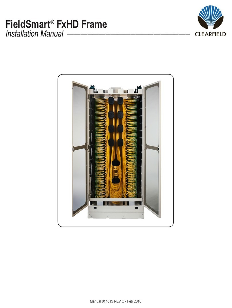
Clearfield FieldSmart FxMP User manual

FieldSmart®FxMP Panel & Standard Frame
Installation Manual ______________________________________________________
Manual 019807 REV A - June 2018

Direct: 763.476.6866 • National: 800.422.2537 • www.SeeCleareld.com • [email protected]
2
FieldSmart®FxMP Panel & Standard Frame
Installation Manual _________________________________________________________
Manual 019807 REV A - June 2018
Table of Contents
Application 3
Description 3
Technical Specications 3
Tools and Optional Materials 4
Standard Frame Floor Installation 5
Standard Frame Raised Floor Installation 7
Standard Frame Interbays and End Guards Installation 11
Standard Frame Grounding 11
FxMP Panel Mounting 12
Cable Mounting and Routing 16
Routing Ribbon Fiber 19
Cassette Removal/Installation 20
Splicing/Buffer Tube Storage 24
FxMP Tie Panels 30
FxMP Designation Card 32
Connector Cleaning Procedure 33
Standard Warranty 36
Proprietary Notice 37
Technical Support 37

3
FieldSmart®FxMP Panel & Standard Frame
__________________________________________________________ Installation Manual
Direct: 763.476.6866 • National: 800.422.2537 • www.SeeCleareld.com • [email protected]
Manual 019807 REV A - June 2018
Application
Description
Technical Specications
FieldSmart FxMP Panel
Port Density 24 72 96 144 288
Dimensions 1.75” H (44.45mm) 3.5” H (88.90mm) 4” H (101.60mm) 6” H (152.40mm) 11” H (279.40mm)
Ratings Compliant to Telcordia GR-63, GR-449, GR-20 and GR-409
Cassette Types Supported Clearview®Blue
Connector Types SC/UPC, SC/APC, LC/UPC, LC/APC, FC/UPC, FC/APC, ST/UPC, MPO
Cable Types Indoor Riser, Indoor Plenum, Indoor/Outdoor, Outdoor (Riser/Non-Rated), Outdoor Armored (Riser/Non-Rated), FieldShield®
Splice Capacity 12 splices in each Clearview Cassette
Storage Capacity One meter of 250 μm ber
Front Protection 3.25” (82.6 mm) or 4.77” (121.16 mm) radius ngers
Color Almond or black
Material Steel and aluminum with almond powder coating
FieldSmart Standard Frame
Dimensions Available in 7’, 8’ or 9’ heights and in either 19” or 23” widths; depth is 10” (5” frame + 5” guard box)
Ratings Compliant to Telcordia GR-449
Cable Entry Clamp Location On-frame (Note: Cable clamps included with panels)
Material Steel
Standard Frame:
FieldSmart FxDS Standard Frames are available in 7’, 8’ or 9’ heights and in 19” or 23” widths. Frames are
seismic-rated and come with an unequal ange. When used with FieldSmart FxMP Panels, they provide the
highest port density in the industry - up to 1,728 ports in a 7’ frame.
FxMP Panel:
The FieldSmart FxMP Panel is a high density, low maintenance ber distribution panel for use in a data
style rack/cabinet, a 19” (482.60mm) or a 23” (584.20mm) frame. Utilizing the Clearview ®Cassette,
FieldSmart FxMP Panels are intelligently designed to provide the user with superior ber access and
craft-friendly, radius protected ber management for routing and deploying ber jumpers.
Standard Frame:
Frames are used for mounting equipment in a central ofce, head end or data
center applications.
FxMP Panel:
Provides an interconnect or cross-connect environment for up to 288 ports of high density ber
for inside plant and outside plant environments.

Direct: 763.476.6866 • National: 800.422.2537 • www.SeeCleareld.com • [email protected]
4
FieldSmart®FxMP Panel & Standard Frame
Installation Manual _________________________________________________________
Manual 019807 REV A - June 2018
Tools and Optional Materials
Tools:
• Sockets (1/2”, 3/4” and 15/16”)
• Ratchet with Extension
• Phillips Screwdriver
• 1/8” Allen Wrench
• Hammer/Rotary Drill
• 5/8” Masonry Drill Bit
• Blowout Air Bulb or Vacuum with Small Diameter Tube
Materials (ordered separately):
Standard Frame:
• Isolation Pad (19” Frame P/N FMA-L1Z-SUB,
23” Frame P/N FMA-L2Z-SUB)
Floor Mounting:
• Floor Mounting Kit (P/N 009106)
Raised Floor Mounting:
• Raised Floor Mounting Kit (P/N 011236)
Patch and Splice Panels:
• Radius Limiter Brackets for Buffer Tube Slack Storage
(P/N 010600)
Ribbon Fiber Protection:
• High Density Ribbon Breakout Kit (P/N 010475)
• Ribbon Fanout Kit (P/N FMA-MZZ)
Radius Limiter Bracket
Breakout Kit Fanout Kit
Isolation Pad

5
FieldSmart®FxMP Panel & Standard Frame
__________________________________________________________ Installation Manual
Direct: 763.476.6866 • National: 800.422.2537 • www.SeeCleareld.com • [email protected]
Manual 019807 REV A - June 2018
Standard Frame Floor Installation
Note: Floor mounting hardware is NOT included with the standard frame. Hardware is sold as a separate line item
(Cleareld P/N 009106).
IMPORTANT: If your frame is to be mounted next to a wall, or there are multiple frames in a line-up, you MUST
install the interbay management and end guards BEFORE mounting the frame to the oor.
Tools:
• Hammer (or rotary) drill (with depth gauge recommended)
• 5/8” masonry drill bit
• Socket wrench set
• Blowout air bulb or vacuum with small diameter tube
Using a 5/8” masonry bit, drill the four required holes to a
minimum depth of 2” (approx. 50mm).
Note: If for some reason you have trouble drilling the 5/8” hole,
Cleareld recommends rst drilling a ¼” pilot hole before drilling
out to 5/8”.
Thoroughly clean the dust from each hole, using a vacuum or
blowout air bulb.
Note: To not degrade the anchor’s installed performance, any unused anchor holes (or other nearby holes) in the
concrete within 3” must be lled with an epoxy ller (pour stone) or equivalent. Filled holes must be fully cured before
anchors are installed and torqued.
19” Frame
9 5/8”
22”
23” Frame
9 5/8”
26”
Determine where the frame is going to be installed. Using the isolation pad as a template, mark the 4 holes where
frame will be secured to the oor.
1.
2.
3.

Direct: 763.476.6866 • National: 800.422.2537 • www.SeeCleareld.com • [email protected]
6
FieldSmart®FxMP Panel & Standard Frame
Installation Manual _________________________________________________________
Manual 019807 REV A - June 2018
Place the isolation pad in position over the predrilled holes and align as necessary. Lift the frame onto the isolation
pad and line up with holes.
Ensure that the anchor’s expansion shield is not expanded. Place the end of the anchor into the predrilled hole.
Repeat for the other drilled holes. Make sure the anchor is fully embedded in the concrete.
Align the edges of the 2” square washer parallel with the slots in the frame base to obtain the maximum material
overlap. Once aligned, tap each anchor/washer assembly until it is seated rmly in the hole and against the 2” square
washer.
Pre-tighten each anchor with a socket wrench or box-end wrench; do not use an open-end wrench (which could easily
slip off and cause injury). Before nal tightening, ensure that the frame is properly aligned (in the row and with any
adjacent frames). Torque each anchor to 60 ft-lbs.
Note: When using the break-off type anchor, a torque wrench is not required. The anchor’s (red) torque cap shears
off at a predetermined torque value (approximately 60 ft-lbs.), leaving a green seal on the bolt head, indicating proper
tightening.
The anchoring line up should look like this:
Note: Square
washers will be
packaged in base
of frames
Threaded Rod
4.
5.
6.
7.
8.

7
FieldSmart®FxMP Panel & Standard Frame
__________________________________________________________ Installation Manual
Direct: 763.476.6866 • National: 800.422.2537 • www.SeeCleareld.com • [email protected]
Manual 019807 REV A - June 2018
Standard Frame Raised Floor Installation
Note: Raised oor mounting hardware is NOT included with the standard frame. Hardware is sold as a separate line item
(Cleareld P/N 011236).
IMPORTANT: If your frame is to be mounted next to a wall, or there are multiple frames in a line up, you MUST
install the interbay management and end guards BEFORE mounting the frame to the oor.
Tools:
• Hammer (or rotary) drill (depth gauge recommended)
• 5/8” masonry drill bit
• Socket wrench set
• Blowout air bulb or vacuum with small diameter tube
Also required is a raised oor mounting kit (Cleareld P/N 011236).
1. 1/2-13 Hex Nut (Qty 8)
2. 1/2 Lock Washer (Qty 4)
3. 1/2 Flat Washer (Qty 4)
4. 1/2-13 x 30 Threaded Rod (Qty 4)
5. Hilti HDI 1/2” Anchor (Qty 4)
6. 1/4 x 2” Flatwasher .515 Hole (Qty 8)
7. Split Tubing 30” (Qty 4)
Screw Sequence for Floor Screw Sequence for Frame
Note: Cleareld recommends installing the anchors directly into the concrete oor.

Direct: 763.476.6866 • National: 800.422.2537 • www.SeeCleareld.com • [email protected]
8
FieldSmart®FxMP Panel & Standard Frame
Installation Manual _________________________________________________________
Manual 019807 REV A - June 2018
Using the isolation pad as a template, mark on the panel(s) of the raised oor the 4 holes where the frame will be se-
cured to the oor. Using a 5/8” drill bit, drill a hole through each of the oblong marks you made with the isolation pad.
Take the threaded rods from the raised oor mounting kit and slide one through each of the holes. Using a hammer
and holding them perpendicular to the oor, tap on the end rmly. The goal is to make a “mark” on the concrete oor
visible enough to see where the 4 holes should be drilled.
Once the concrete oor is marked, remove the threaded rods and oor panels. Using a 5/8” masonry bit, drill the four
required holes to a minimum depth of 2” (approx. 50mm).
Note: If for some reason you have trouble drilling the 5/8” hole, we
recommend rst drilling a 1/4” pilot hole before drilling out to 5/8”.
Thoroughly clean the dust from each hole, using a vacuum or
blowout air bulb.
Note: To not degrade the anchor’s installed performance, any unused
anchor holes (or other nearby holes) in the concrete within 3” must be
lled with an epoxy ller (pour stone) or equivalent. Filled holes must be fully cured before anchors are installed and
torqued.
19” Frame
9 5/8”
22”
23” Frame
9 5/8”
26”
1.
2.
3.
4.

9
FieldSmart®FxMP Panel & Standard Frame
__________________________________________________________ Installation Manual
Direct: 763.476.6866 • National: 800.422.2537 • www.SeeCleareld.com • [email protected]
Manual 019807 REV A - June 2018
Install anchors into the oor. Replace raised oor panels and
insert threaded rods through the four holes.
Note: You are not installing the rods at this point. You are
measuring the rods to be cut to the appropriate length.
Measure the rods 2.5” above the oor and mark with a
permanent marker. Remove the rods and cut each rod at the
mark. Remove the oor panels.
Before installing rods back into the oor, place a nut and then
a washer on the threaded rods. Take the rod and install it into
the anchor installed in the oor.
Tighten the nut down to secure the rod into the oor. Tighten
each bolt to 65 ft-lbs., +10, -0 ft-lbs. The anchor will expand
and secure itself to the oor.
Once all four rods are secure, thread another hex nut, then
washer on each rod. Make sure the nut and washer are
approximately ½” below the raised oor level. This hardware
will be tightened down AFTER the frame is set into place but
BEFORE securely bolting the frame to the oor.
5.
6.
7.
8.
9.

Direct: 763.476.6866 • National: 800.422.2537 • www.SeeCleareld.com • [email protected]
10
FieldSmart®FxMP Panel & Standard Frame
Installation Manual _________________________________________________________
Manual 019807 REV A - June 2018
Place the oor panels into position, and tighten the previously installed nuts below the raised panel until they make
contact with the panel. Put the isolation pad into place (isolation pad may look different than example).
Lift the frame into place.
Place the square washers onto each rod. Align the edges of the 2” square washer parallel with the slots in the frame
base to obtain the maximum material overlap. Install the isolation washers (packaged with the isolation pad) onto each
rod.
Install the remaining hardware (washers, nuts, etc) from the raised oor installation kit.
Note: Square
washers will be
packaged in base
of frames
Threaded Rod
10.
11.
12.
13.

11
FieldSmart®FxMP Panel & Standard Frame
__________________________________________________________ Installation Manual
Direct: 763.476.6866 • National: 800.422.2537 • www.SeeCleareld.com • [email protected]
Manual 019807 REV A - June 2018
Standard Frame Interbays and
End Guards Installation
Attach the interbay to the front ange of
the frame with the hardware provided.
Next, install the end guard to the
interbay with the included hardware.
Note: The 9 foot interbay is shipped in
two pieces per side.
Note: End guards are only needed on
frames at the end of the frame line-up.
Repeat for the other side of the frame.
End Guard Interbay
1.
2.
3.
After
End Guard
Before
Interbay
Frame
Standard Frame Grounding
Cleareld provides a ground bar with the Standard Frame
which can be installed on the frame. Ground per your local
practices.
FrameInterbay

Direct: 763.476.6866 • National: 800.422.2537 • www.SeeCleareld.com • [email protected]
12
FieldSmart®FxMP Panel & Standard Frame
Installation Manual _________________________________________________________
Manual 019807 REV A - June 2018
FxMP Panel Mounting
The FieldSmart FxMP Panel will arrive with reversible mounting brackets unattached. Depending on the size of the frame,
you will attach the mounting brackets in a 19 inch or 23 inch conguration.
The exception to this will be the 1RU panel, which has mounting brackets that are not reversible. These mounting brackets
will attach to a 19 inch frame. Extender brackets will be supplied with the panel, which can be attached to the mounting
brackets in order to mount the panel to a 23 inch frame.
Installing Mounting Brackets for 19 Inch Frame
If installing reversible mounting brackets for a 19 inch frame
conguration, the large side of the bracket will be mounted to the
panel. The smaller side will be used to mount the panel to the
frame.
Note: Mounting brackets for the left and right sides of the panel
are identical, interchangeable parts.
1.
Align the reversible mounting bracket so that the holes in the bracket and the panel body match up. Using the
provided screws (three per bracket) secure the bracket into place. Repeat for the other side.
Note: There are four bracket-to-panel screw holes on each side of the bracket and panel. One of the holes will be a
smaller size, used for a bonding screw with the NEBS panel.
2.

13
FieldSmart®FxMP Panel & Standard Frame
__________________________________________________________ Installation Manual
Direct: 763.476.6866 • National: 800.422.2537 • www.SeeCleareld.com • [email protected]
Manual 019807 REV A - June 2018
Installing Mounting Brackets for 23 Inch Frame
If installing reversible mounting brackets for a 23 inch frame
conguration, the small side of the bracket will be mounted to
the panel. The large side will be used to mount the panel to the
frame.
Note: Mounting brackets for the left and right sides of the panel
are identical, interchangeable parts.
1.
Align the reversible mounting bracket so that the holes in the bracket and the panel body match up. Using the
provided screws, three per bracket, secure the bracket into place. Repeat for the other side.
Note: There are four bracket-to-panel screw holes on each side of the bracket and panel. One of the holes will be a
smaller size, used for a bonding screw with the NEBS panel.
2.

Direct: 763.476.6866 • National: 800.422.2537 • www.SeeCleareld.com • [email protected]
14
FieldSmart®FxMP Panel & Standard Frame
Installation Manual _________________________________________________________
Manual 019807 REV A - June 2018
Installing Mounting/Extender Brackets for 1RU Panel
Align the mounting bracket so that the holes in the bracket and panel body match up. Using the provided screws, two
per bracket, secure the bracket in place. Repeat for the other side.
Note: There are three bracket-to-panel screw holes on each bracket and side of the panel. One of the holes will be a
smaller size, used for a bonding screw with the NEBS panel.
1.
If mounting the 1RU panel in a 23 inch frame, extender brackets will need to be installed. These attach on each side
of the panel to the mounting brackets via the two 12-24 x ½” screws provided.
2.

15
FieldSmart®FxMP Panel & Standard Frame
__________________________________________________________ Installation Manual
Direct: 763.476.6866 • National: 800.422.2537 • www.SeeCleareld.com • [email protected]
Manual 019807 REV A - June 2018
Mounting Panel Into Frame
While supporting the panels in the desired rack location, insert and tighten the four mounting screws (two 12-24 x ½” thread
cutting screws per side) to secure the panel to the frame. In order to help align the panel, it is also recommended that
vertical and horizontal holes are used on each side for mounting.
19 Inch Mounting 23 Inch Mounting
1RU Panel - 19 Inch Mounting 1RU Panel - 23 Inch Mounting

Direct: 763.476.6866 • National: 800.422.2537 • www.SeeCleareld.com • [email protected]
16
FieldSmart®FxMP Panel & Standard Frame
Installation Manual _________________________________________________________
Manual 019807 REV A - June 2018
Cable Mounting and Routing
Choose a green cable clamp that is close to the same size but
slightly bigger than the cable you plan to mount.
The difference in size can be made up by either wrapping the
cable with some of the provided grommet tape, or laying a small
strip of grommet tape in the bottom side of the cable clamp shell.
Each panel comes with two types of cable mounting brackets. One is used for applications where you have access to
pre-drilled and tapped holes in the back of the frame, and one is for instances where these holes are not available.
Note: The standard frame Cleareld offers already has rear mounting holes.
Frames with rear
mounting holes
Frames without rear
mounting holes
Patch Only panels have tails which may need to be routed through the frame and up to the appropriate ladder
racks or down into the raised oor before securing the cable to the frame.
1.
2.
3. Place one cable clamp on each side of the cable, and using the
two mounting screws provided, secure the cable to the cable
mounting bracket.
Note: The angle of cable mounting can be adjusted by pivoting
the bracket on one of the mounting holes and securing it down
with the other. A greater range of angles can be achieved by
ipping the bracket to the other side.

17
FieldSmart®FxMP Panel & Standard Frame
__________________________________________________________ Installation Manual
Direct: 763.476.6866 • National: 800.422.2537 • www.SeeCleareld.com • [email protected]
Manual 019807 REV A - June 2018
Mount the cable to the bracket as previously shown. The angle of the
cable can be adjusted by using the different sets of threaded holes in
the bracket.
If no rear mounting holes are available, the other bracket can be used.
You will need to hold the bracket up to the frame and drill a pilot hole
into the frame as shown. Then, you can mount the bracket using the
self-tapping screw included with the panel.
4.
5.
Cleareld offers optional radius limiter assemblies (P/N 010600),
used in pairs for storing buffer tube slack on the frame, outside of
panels, shown here. This part number is ordered and shipped
separately from the frame or panels.
Note: Panels shown in images may not match product received.
Cable mounting will be performed in the same manner regardless.
6.

Direct: 763.476.6866 • National: 800.422.2537 • www.SeeCleareld.com • [email protected]
18
FieldSmart®FxMP Panel & Standard Frame
Installation Manual _________________________________________________________
Manual 019807 REV A - June 2018
Once you’ve mounted the panel and the cable is attached to the frame, open up your cable. Cleareld recommends a
cable opening of 11 feet (up to 8ft of slack (depending upon panel size) and 3ft for splicing in the cassette). Proceed to
mounting the cable to the panel.
Use the included mounting screws to fasten the cable clamps and
cable to the rear cable bracket. The cable should be mounted so
that the breakout is slightly beyond the end of the clamp.
Note: Panels shown in images may not match product received.
Cable mounting will be performed in the same manner regardless.
Clamp the cable to the panel using the same method you used
to mount it to the frame, choosing the closest size pair of cable
clamps, and using grommet tape to make up the size difference.
If mounting the cable to the back of
a 1RU panel, a vinyl coated P-clip
(supplied as a ship-along) will need
to be used to secure the cable. Use
grommet tape around the cable as
needed to increase the size of the
cable for proper grip.
7.
8.
9.
10.

19
FieldSmart®FxMP Panel & Standard Frame
__________________________________________________________ Installation Manual
Direct: 763.476.6866 • National: 800.422.2537 • www.SeeCleareld.com • [email protected]
Manual 019807 REV A - June 2018
Routing Ribbon Fiber
The High Density Ribbon Breakout Kit and Ribbon Fanout Kit are both used to protect bare ribbon on a frame before the
bers enter the protection of a panel body or cassette. The High Density Ribbon Breakout Kit allows the user to breakout a
high ber count cable (864 bers max) into manageable 144 ber groups that can be further broken down with the use of
the Ribbon Fanout Kit. Each Ribbon Fanout Kit breaks out ribbon stacks (max 12 ribbons) of 250 um bers (max 12 bers
per ribbon) into color-coded breakout tubes. The breakout tubes with individual ribbons can then be routed to your cassettes
and secured into the tray like a buffer tube.
The High Density Ribbon Breakout Kit can also accommodate a breakout of a 1728 SpiderWeb Ribbon cable. This will be
used in conjunction with the round Ribbon Fanout Kit (P/N FMA-MZZ-ROUND) which can hold 24 bers (2 subunits of 12
bers) each.
Note: The installation manuals for both products are shipped with the kits. Examples shown below.
High Density Ribbon
Breakout Kit
Ribbon
Fanout Kit
Kits During
Installation
Completed
Installation

Direct: 763.476.6866 • National: 800.422.2537 • www.SeeCleareld.com • [email protected]
20
FieldSmart®FxMP Panel & Standard Frame
Installation Manual _________________________________________________________
Manual 019807 REV A - June 2018
Cassette Removal/Installation
In order to access the front of the panel where the cassettes
are located, rst remove the front protection door. Release
the push/pull plungers by pulling until you feel it disengage
with a click.
1.
Repeat for the other side and swing the door down.
If you wish to remove the door, this can be done by gently exing the door to create the space needed to pull the
hinges out of their sockets.
2.
3.
Table of contents
Other Clearfield Control Panel manuals
Popular Control Panel manuals by other brands
AERMEC
AERMEC MULTI CONTROL Booklet

CityGrow
CityGrow CG100HHB-SKY user manual
Carrier
Carrier Aritech Reliance XR Series Installation and programming guide
St. Croix
St. Croix DHC3000 instructions
Bosch
Bosch D7412G Installation & Troubleshooting Quick Reference Guide

HST
HST Addressable fire alarm MN-300 operating instructions
