Tiras AM-OUT2R User manual
FIRE ALARM SYSTEMS
Input/Output device АМ-OUT2R
Passport
AAZCh. 425532.014 PS
DSTU ISO 9001:2015
Serial number:
Firmware version:

2
This passport contains information on the design, and operation of the I/O
device AM-OUT2R (further - device), which is used as part of addressable fire
alarm systems, based on the fire control panel (FCP) Tiras PRIME A.
The device meets the requirements of the standards DSTU EN54-18, DSTU
EN54-17.
1 List of abbreviations
PS –power supply unit;
SCI –short circuit isolator;
AFAS –addressable fire alarm system;
AI –addressable interface;
NC –normally closed;
NO –normally open.
2 Purpose
The device is intended to increase the number of relay outputs in AFAS. The
device has a plastic housing, its view with the cover removed is shown in Figure 1.
3 Declarations of manufacturer
The device design meets the requirements of the quality management
system, which contains the set of design rules for all its elements.
All components of this device are used as intended and under the conditions
of their operation correspond to the environmental conditions outside the
housing in accordance with class 3k5 IEC 60721-3-3.
4 Technical features
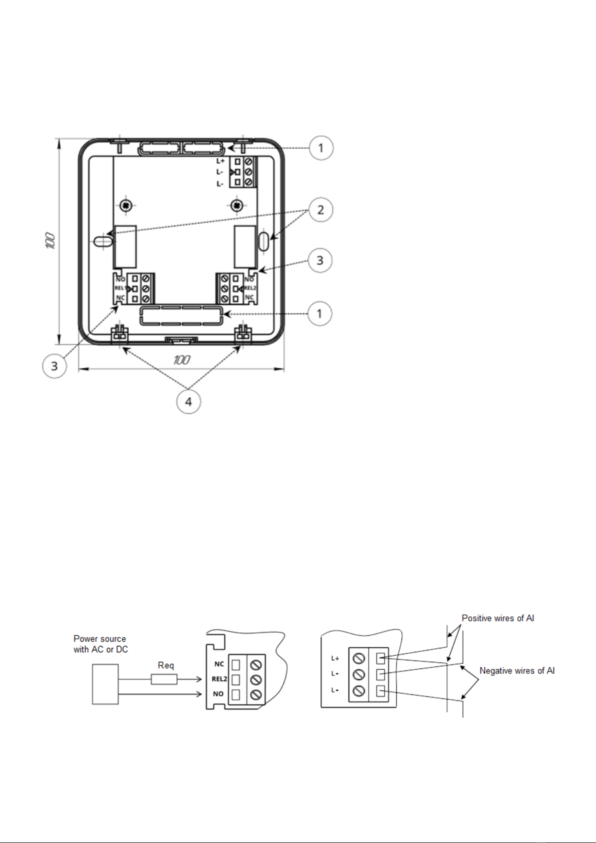
4.1 The list of terminals and their functions is given in Table. 1. Their location is
shown in Fig.1.
Table 1
Terminal
name
Functional characteristics
L+
The input for the connection of a positive AI wire.
L-
The input for the connection of a negative AI wire. There are two terminals
separated by SCI.
REL1
The middle contact output of the K2 relay contact group
NO
(REL1)
The output of the normally open contact of the K2 relay contact group is
closed to the middle contact when triggered.
NС
(REL1)
The output of the normally closed contact of the K2 relay contact group
opens with the middle contact when triggered
REL2
The output of the middle contact of the K1 relay contact group
NO
(REL2)
The output of the normally open contact of the K1 relay contact group is
closed to the middle contact when triggered
NС
(REL2)
The output of the normally closed contact of the K1 relay contact group
opens with the middle contact when triggered

3
4.2 Technical features of the device are given in Table. 2.
Table 2
Feature name
Value
General
Dimensions WxHxD, mm
100 100 30
Net weight, kg
0,11
Enclosure protection degree
ІР30
Meantime to failure, hours, not less
40 000
Average lifetime, years, not less
10
Time to detect faults, s, not more than
10
Power supply
Supply voltage through AI, V
20 –25
Maximum current consumption, standby mode/alarm mode from
AI, mA
0,40/0,45
Outputs
Current through the NO contact at a voltage of 250 V AC, A, not
more than
15
Current through the contact NC at a voltage of 250 V AC, A, not
more than
5
Current through the NO contact at a voltage of 30 V DC, A, not more
than
15
Current through the NC contact at a voltage of 30 V DC, A, not more
than
15
SCI
Maximum SCI opening voltage, V
15,0
Minimum SCI recovery voltage, V
4,2
Maximum current through SCI in the closed state, mA
65
Maximum SCI opening current, mA
75
Maximum leakage current through SCI (in the open state), mA
4,2
Maximum transient resistance of SCI in the closed state, Ohm
0,09
4.3 LED indicators located on the device board are used to indicate the
operating modes and the device status. The purposes of the indicators are as
follows:
1)HL1 (green):
-blinking once in four seconds –standby mode indication;
-blinking with an interval of 0.5 s (not more than 4 s) –the indication of
the device registering process in the AI.
2) HL3 (red): double blinking –the indication of a fault.
3) alternating blinking indicators HL1, HL3 –the device is marked for
visual search in the premise.
4
5 Connection
5.1 To access the terminals of the device, unscrew the 2 screws on the
underside of the housing (Fig. 1) and remove the cover. Connect the device to
the AI and actuators according to Figure 2.
1. Slots for wires.
2. Holes for mounting on a wall.
3. Cutouts for wires.
4. Screws for fixing a cover.
Figure 1 –View of the device with the cover removed
5.2 The wires inside the housing should be laid in such a way that they do
not interfere with closing the lid and do not fall between the indicators and the
window in the housing lid.
5.3 Wires can only be connected to the terminals of the device when there is
no voltage from external power supplies.
5.4 The device board has special cutouts for fastening cables or wires after
installation in the K1, K2 relay terminals (Fig. 1).
Figure 2 shows the connection to the NO contact of relay K2. The connection
to the NC contact of relay K2 and relay K1 is similar.
Req - equivalent load, the resistance of which provides current limitation through the
relay contacts at the level specified in Table 2 (lamp, starting device, relay device, etc.);
Positive wires AI - AI wires connected to terminals L1-L4 of the FCP;
Negative AI wires are AI wires connected to terminals G1-G4 of the FCP.
Figure 2 - Schemes of connections of external circuits to the device terminals

5
6 Settings
6.1 After the supply voltage appears in the AI on the connected device, the
automatic registration indication (4.3) is switched on. The device is in standby
mode.
The outputs of the device are set in accordance with the FCP
operating manual.
6.2 During setup, it is recommended to disconnect the actuators from the
output terminals to avoid incorrect control.
6.3 By default, the device outputs are set to "Not used" mode.
7 Packaging
7.1 After device unpacking it is need:
- visually inspect the device and make sure there is no mechanical damage
on it;
- check the delivery set according to table 3.
Table 3
Name
Code
Number
Note
АМ-OUT2R device
AAZCh.425532.014
1
Passport
AAZCh.425532.014 PS
1
Nylon coupler CV100
2
8 Operation, storage, and transportation conditions
The device is intended for continuous 24h operation in the premises under
regulated climatic conditions. Operating temperature range: from - 10°Сto +55°С, at
relative humidity 93%.
Packaged devices are stored in warehouses under the following conditions: air
temperature from - 50°Сto +55°С, relative humidity should not exceed 98% at a
temperature of 35°С. There should be no aggressive impurities in the air causing
corrosion in the premises where the devices are stored.
Packaged devices are transported by low-tonnage shipments at any distance by
road and rail in closed vehicles in accordance with the rules of transportation
applicable to each type of transport. When placing and securing boxes with packed
devices during transportation, ensure a stable position of the boxes to prevent
shifting and bumps between them. During loading and transportation, the
requirements of handling signs on the packaging should be met.
9 Acceptance certificates
The AM-Converter meets the requirements of regulatory and technical
documents and is suitable for operation complete with FCP Tiras PRIME A.
The serial number is indicated in the lower right corner of the title page of
this passport. The date of acceptance (stamp) is on the last page of the passport.

6
10 Warranty obligations
The manufacturer guarantees the device complies with the requirements of
regulatory and technical documents during the warranty period of operation
under the conditions of transportation, storage, and the operation specified in
this passport.
The warranty period is 36 months and starts at the date of sales specified in
the operating documents for the device or in other accompanying documents
(sales contract, invoice, bill, etc.). If you cannot provide a document confirming
the date of sale of the device, the warranty period starts from the date when the
device was produced.
___________________ ____________________
(date of sale) (seller’s signature) stamp
11 Limitation of liability
The manufacturer reserves the right to refuse warranty service of the device
in controversial circumstances. The manufacturer also has the right to make a
final decision on whether the device is to be serviced under the guarantee.
Actions and damages that result in loss of warranty service:
1) damage caused by natural phenomena (fire, flood, wind, earthquake,
lightning, etc.);
2) damage caused by a violation of the installation rules or the provision of
improper conditions for the operation of the device, including:
−faulty grounding;
−over-voltage;
−high humidity and vibration;
3) damage caused by foreign objects entering the device, liquids, insects
and others;
4) mechanical damage to components of the device (chips, dents, cracks,
broken contact terminals, etc.);
5) damage resulting from unauthorized repair;
6) damage caused by violation of the rules of transportation, storage and
operation;
7) changing, removing, rubbing or damaging the serial number of the
device (or labels with serial numbers on the device).
12 Information on repair
The device is repaired by the manufacturer or its authorized representative.
This device is repaired for free, in case the warranty period is not expired, it
was operation in accordance with this passport.

7
The device is sent for repair with a letter which should include: the
description of the malfunction, the place of operation and the contact phone of
the person in charge of repair.
13 Information on declarations of conformity to technical regulations
and certificates
This device meets the requirements of following mandatory technical
regulations:
-Technical regulations on electromagnetic compatibility of equipment;
-Technical regulations restricting the use of certain hazardous substances
in electrical and electronic equipment.
Certificate of compliance with the requirements of DSTU EN 54 series
standards issued by the State Certification Center of the SES of Ukraine.
The Quality Management System of Tiras-12 LTD is certified in accordance
with DSTU ISO 9001: 2015.
The full text of declarations of compliance with technical regulations and
certificates are available on the website https://tiras.technlogy.
14 Disposal
After the expiry of the service life of the device its utilization is carried out in
accordance with the current legislation, separate from household waste.
In accordance with the EU Directive 2012/19/EU on waste electrical
and electronic equipment, the disposal of device should be done
separately from household waste. To dispose of the device, it must
be delivered to a point of sale or a local processing point.

Table of contents
Other Tiras Fire Alarm manuals


Popular Fire Alarm manuals by other brands


SILENT KNIGHT
SILENT KNIGHT 5700 Installation and operation manual

Ampac
Ampac Warning Sign 4210-011 installation guide

Teletek electronics
Teletek electronics SensoIRIS BSOU IS Installation instruction

Notifier
Notifier ID50 SERIES installation, commissioning & configuration manual

LST
LST Vds 245402 Specifications

Global Fire Equipment
Global Fire Equipment ORION EX MINI-REP installation manual


