Tiras AM-OUT1R+ User manual
1
FIRE ALARM SYSTEMS
Input/output device АМ-OUT1R+
Passport
AAZCh. 425532.016PS
DSTU ISO 9001:2015
Serial number:
Firmware version:

2
This passport contains information on the design, operation and operation rules of the
addressable I/O device AM-OUT1R+ (further - the device), which is used in addressable fire alarm
systems, based on the fire alarm control panel Tiras PRIME A. The device meets the requirements of
DSTU EN54-17, DSTU EN54-18.
1 LIST OF ABBREVIATIONS
SCI - short circuit isolator;
FCP –Fire Control Panel "Tiras PRIME A";
AFAS - address fire alarm system;
AI - addressable interface.
2 PURPOSE
The device is designed to increase the number of inputs and outputs AFAS. The device is
produced in a plastic housing. The appearance of the device with the cover removed is shown in Fig.1
1. Holes for mounting on the wall.
2. Holes for cable entry.
3. Screws for fixing of a cover of the case.
Figure 1 - Appearance of the device with the cover removed
3 Technical features
3.1 The list of terminals and their functions is given in table. 1. Their location is shown in Fig.1.
Table 1
Terminal name
Functional characteristic
L+
The input for the connection of a positive AI wire.
L-
The input for the connection of a negative AI wire. There are two terminals
separated by SCI.
GND
Common input with circuit ground potential.
IN1, IN2
Universal parametric inputs (see Table 2).
CON
CON Supply voltage control input - 220 V, 50 Hz.
REL
The relay contact group common output is switched to NO or NC. Normal state -
REL closed on NC.
NO
Output of normally open relay contact
NС
Output of normally closed relay contact

3
3.2 Technical characteristics of the device are given in table 2.
Table 2
Name
Value
General
Dimensions WxHxD, mm, not more than
10010030
Weight, kg, not more than
0,1
Enclosure protection class
ІР30
Average operating time per failure, h, not less than
40 000
Average service life, years, not less than
10
Fault detection time, s, not more than
10
Power supply
Supply voltage through AI, V
20 –25
Current consumption from AI, standby mode / input activation warning mode, mA,
not more than
0,35/0,60
Current consumption from AI, standby mode / input fault warning mode, mA, not
more than
0,35/0,65
Parametric inputs IN1 –IN2
Line resistance in the state of short circuit, kOhm
0 –1,5
Line resistance in the state of activation (the low level), kOhm
1,6 –24,9
Range of resistance values of the line in the state of the next mode, kOm
25 –35
Line resistance in the state of activation (the low level), kOhm
35,1 - 60
Line in the state of open circuit, kOhm
60,1 –∞
Relay output
Current through contact NO (250V AC), A, not more than
15
Current through contact NC (250V AC), A, not more than
5
Current through contact NO (30V DC), A, not more than
15
Current through contact NC (30V DC), A, not more than
15
SCI
Opening voltage, V, not more than
15,0
Restoring voltage, V, not less than
4,2
Current through SCI in the closed state, mA, no more than
65
SCI opening current, mA, no more than
75
Leakage current through SCI (in the open state), mA, not more than
4,2
The transient resistance of the SCI in the closed state, Ohm, not more than
0,09
Input CON
Range of control for AC power, V
100 –230
3.3 LED indicators located on the board are used to indicate the operating modes and status of
the device. Assignment of indicators HL1, HL2 (Fig. 1):
1) HL1 (green):
-blinking 1 time in 4 s - standby mode indication;
-blinking with an interval of 0.5 s (for not more than 4 s) - indication of the device registering
process in the AI.
2) alternating blinking indicators HL1, HL2 - the device is marked for visual search in the zone.
4 CONNECTIONS
4.1 To access the terminals, unscrew the 2 screws on the underside of the housing and remove the
cover. Figure 2 shows the connection of the device to the AI and control line 220 V, 50 Hz.

4
Figure 2 - Connection diagrams of AI and control lines 220V, 50 Hz
Positive wires of AI –AI wires connected to terminals L1-L4;
Negative wires of AI–AI wires connected to terminals G1-G4.
Figure 3 shows the possible options for connection the activation devices to the IN1 and IN2
inputs of the device. For example, the activation device is shown as a relay.
It is also possible to use the button as the activation device, when the resistance of the line
provided according to table 2.
Rt –terminal resistor, the resistance value of which should satisfy the conditions of formation of
the standby mode in accordance with table 2;
Rl –an additional resistor, the resistance value of which should satisfy the conditions of formation
of the device activation mode (Table 2).
а)
b)
Figure 3 - The connection diagram of external circuits to inputs IN1 and IN2 of the device
a) The connection diagram of the relay with NO contact in parallel with the terminal resistor Rt.
b) The connection diagram of the relay with NC contact in series with the terminal resistor Rt.
Notes.
1. When choosing the values of resistance Rt and Rl, you should take into account the total resistance of
the line when the relay is activated, this value should not be equal to Rd - the resistance of the indeterminate
state of the line. Rd is 100 Ohms between the ranges of inputs modes.
2. Switching the device to the activation warning mode is possible only from the standby mode. In the
event of a fault (line short circuit or open circuit), the device can be restored when returning to the standby
mode.
4.2 Actuators should be connected according to Figure 4.
Positive wires
of AI
Negative wires
of AI
220V, 50Hz
Rt
Rt
Rl
5
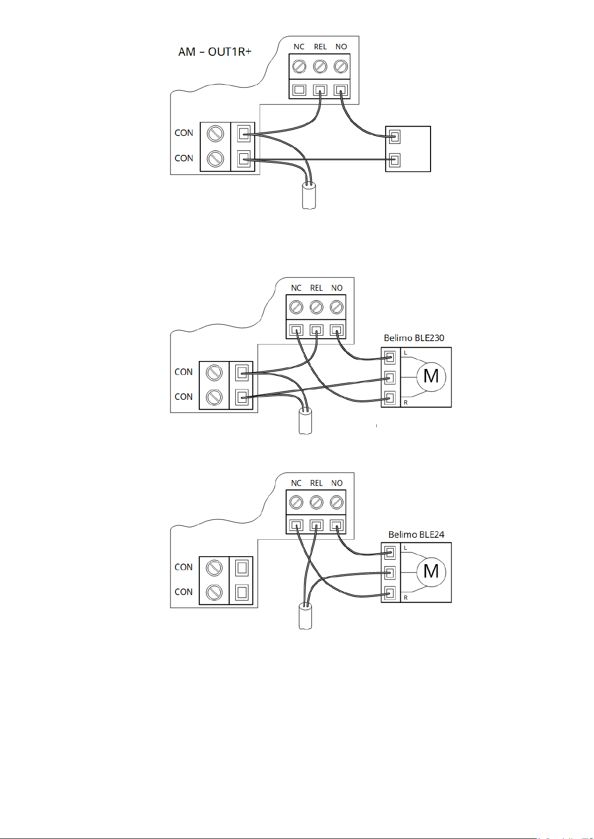
Figure 4 - Scheme of actuators connection to relay terminals
An example of the use of a device for control the smoke extraction valve equipped with BELIMO
actuator series BLE and BE is shown in Figure 5.
а)
b)
Figure 5 - Wiring diagram of smoke extraction valves
Notes.
1. A 24V power supply should be used to connect the BLE24 (BE24) series drives, and voltage control is not possible.
2. A bipolar relay is installed on the board and switching occurs with the receipt of the pulse, the relay retains its
state when the supply voltage AI disappears.
4.3 Wires inside the housing should be laid in such a way that they do not interfere with closing
the cover and do not fall between the indicators and the window in the housing cover.
4.4 The wires can only be connected to the terminals of the device when there is no voltage from
external power supplies.
220V, 50Hz
Actuator
220V, 50Hz
24V
6
5 SETTINGS
5.1 When the supply voltage appears in the AI on the connected device, the automatic
registration indication (3.3) is switched on. Then the device goes into a mode that depends on the input
settings and the state of external devices connected to it (Fig. 3).
The inputs and outputs of the device are configured in accordance with the FCP
operation manual.
5.2 By default, the outputs of the device are set to "Not used".
6 PACKAGING
6.1 After unpacking the device it is necessary:
- visually inspect the device and make sure there is no mechanical damage on it;
- check the delivery set according to table 3.
Table 3
Name
Designation
Quantity, pcs
Device АМ-IN4
AAZCh.425532.016
1
Passport
AAZCh.425532.016 PS
1
Resistor 0,5W –30 kОhm ± 1%
2*
Resistor 0.5 W –10 kОhm ± 1%
2**
Notes:
* –Rt for IN1, IN2;
** –Rl for IN1, IN2.
7 OPERATION, STORAGE, AND TRANSPORTATION CONDITIONS
The device is intended for continuous 24h operation in the premises under regulated climatic
conditions. Operating temperature range: from - 10°Сto +55°С, at relative humidity 93%.
Packaged devices are stored in warehouses under the following conditions: air temperature from - 50°С
to +55°С, relative humidity should not exceed 98% at a temperature of 35°С. There should be no aggressive
impurities in the air causing corrosion in the premises where the devices are stored.
Packaged devices are transported by low-tonnage shipments at any distance by road and rail in closed
vehicles in accordance with the rules of transportation applicable to each type of transport. When placing
and securing boxes with packed devices during transportation, ensure a stable position of the boxes to
prevent shifting and bumps between them. During loading and transportation, the requirements of handling
signs on the packaging should be met.
8 INFORMATION ON DECLARATIONS OF CONFORMITY TO TECHNICAL REGULATIONS AND
CERTIFICATES
This device meets the requirements of following mandatory technical regulations:
-Technical regulations on electromagnetic compatibility of equipment;
-Technical regulations on the restriction of the use of certain hazardous substances in electrical
and electronic equipment.
Certificate of compliance with the requirements of DSTU EN 54 series standards issued by the
State Certification Center of the SES of Ukraine.
The Quality Management System of Tiras-12 LTD is certified in accordance with DSTU ISO 9001: 2015.
The full text of declarations of compliance with technical regulations and certificates are available
on the website https://tiras.technlogy.
9 ACCEPTANCE CERTIFICATES
The device meets the requirements of regulatory and technical documents and is recognized as
suitable for operation. Evidence of acceptance is a sticker on the passport. The date of acceptance
coincides with the date of manufacture.

7
10 WARRANTIES AND REPAIRS
"Tiras-12" LTD (further - the manufacturer) guarantees compliance of the device with the
requirements of current regulatory and technical documents during the warranty period under the
conditions of transportation, operation and storage.
The warranty period is 36 months and starts at the date of sales specified in the operation
documents for the device or in other accompanying documents (sales contract, invoice, bill, etc.). If
you cannot provide a document confirming the date of sale of the device, the warranty period starts
from the date when the device was produced.
___________________ ____________________
(date of sale) (seller’s signature) Stamp
The device is repaired by the manufacturer. This device is repaired for free, in case the warranty
period is not expired, it was operation in accordance with this passport.
The device is sent for repair, together with a letter, which should include: the description of the
malfunction, the place of operation and the contact phone of the person in charge of repair.
11 LIMITATIONS OF LIABILITY
The manufacturer reserves the right to refuse warranty service of the device in controversial
circumstances. The manufacturer also has the right to make a final decision on whether the device is
to be serviced under the guarantee.
Actions and damages that result in loss of warranty service:
1) damage caused by natural phenomena (fire, flood, wind, earthquake, lightning, etc.);
2) damage caused by a violation of the installation rules or the provision of improper conditions
for the operation of the device, including:
−faulty grounding;
−over-voltage;
−high humidity and vibration;
3) damage caused by foreign objects entering the device, liquids, insects and others;
4) mechanical damage to components of the device (chips, dents, cracks, broken contact
terminals, etc.);
5) damage resulting from unauthorized repair;
6) damage caused by violation of the rules of transportation, storage and operation;
7) changing, removing, rubbing or damaging the serial number of the device (or labels with
serial numbers on the device).
12 DISPOSAL
After the expiry of the service life of the device its utilization is carried out in accordance with the
current legislation, separate from household waste.
In accordance with the EU Directive 2012/19/EU on waste electrical and electronic
equipment, the disposal of device should be done separately from household waste.
To dispose of the device, it should be delivered to a point of sale or a local processing
point.

Table of contents
Other Tiras Fire Alarm manuals


Popular Fire Alarm manuals by other brands


Siemens
Siemens FS720 Series Mounting & installation

Simplex
Simplex 4007ES Panels User & installation manual

Wheelock
Wheelock RSSR-2415C installation instructions

VSAIL
VSAIL VI-6811 Installation and operation manual

LST
LST SIM016-3 Specification sheet

Cooper Wheelock
Cooper Wheelock RSS-24110W installation instructions


