Global Fire Equipment ORION EX MINI-REP User manual

Manufacturers of Fire Detection Equipment
globalfire.pt
INSTALLATION MANUAL 1.0 - 06/2015
ORION EX MINI-REP
INSTALLATION MANUAL
VERSION 1.0 - 06/2015
ORION EX MINI-REP
EXTINGUISHING CONVENTIONAL REPEATER PANEL

Manufacturers of Fire Detection Equipment
globalfire.pt
INSTALLATION MANUAL 1.0 - 06/2015
ORION EX MINI-REP
OVERVIEW
IMPORTANT SAFETY NOTES
The ORION EX MINI-REP will provide remote control and system display status from multiple locations to an
Orion based Conventional Fire Alarm system. Its reduced dimensions make it ideal for installation in
reception areas or security booths where it would be impractical and unattractive to install a full size
control panel. ORION EX MINI-REP can be connected to the Orion Conventional Panel using 4 different
interconnecting technologies: RS-232, RS-485, Fiber Optics and TCP/IP . The unit is provided as standard
with an RS-232 interface. Power for the ORION EX MINI-REP can be supplied from the control panel’s
auxiliary power output or an external 24Volt DC power supply if required.
This equipment must only be installed and maintained by a suitably qualified and technically
competent person.
A basic knowledge and training in the installation of Fire Detection systems is assumed.
The Fire Detection system should be designed by a suitably qualified person with reference to the Local
Regulations and Guidance from the fire Officer where applicable.
All wiring should be carried out with no power present in any part of the fire detection system.

INSTALLATION
In order to correctly install an Orion Ex Mini-Rep, the following steps should be taken:
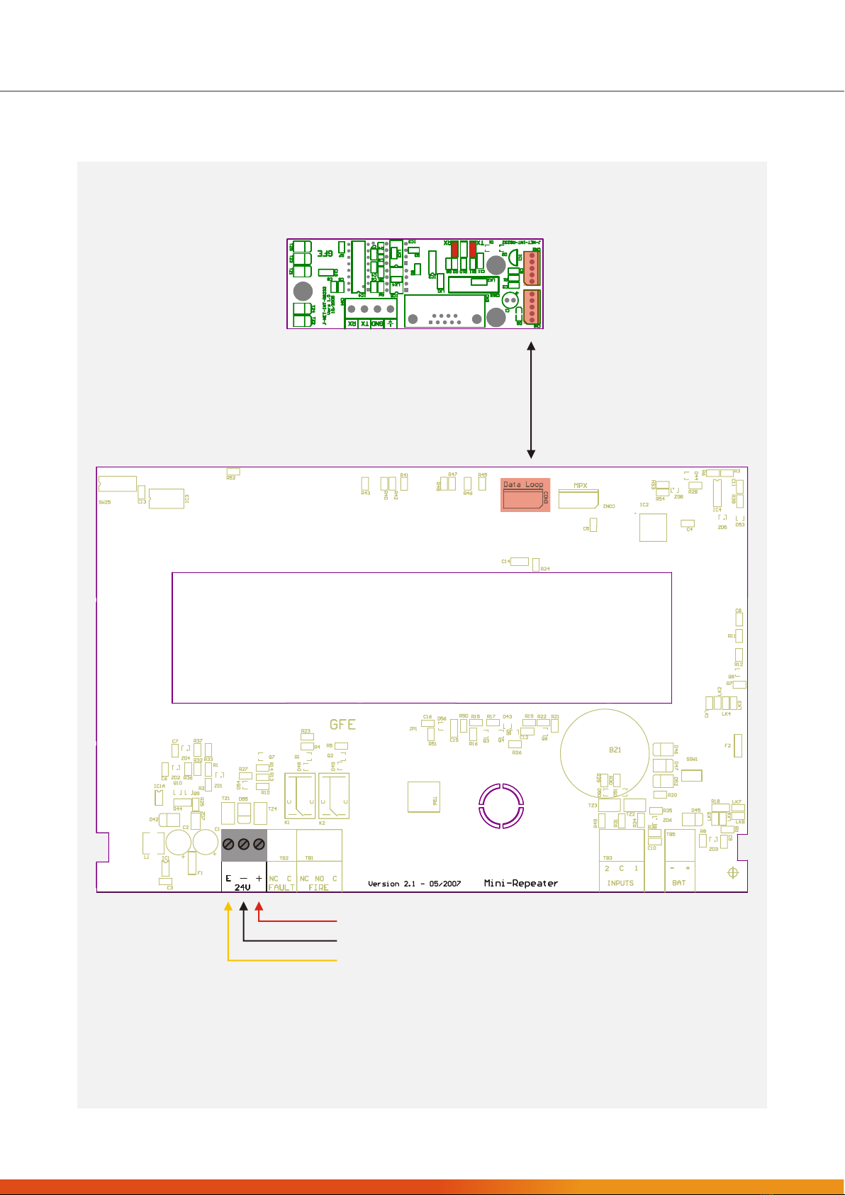
a) Remove the 4 screws fixing Orion Ex Mini-Rep Display to the unit’s back box.
b) Disconnect flat cable linking Orion Ex Mini-Rep Display to Interface Board.
c) Fix unit’s back box in required mounting position using the mounting holes provided. See Figure 1
d) Reconnect flat cable connecting Orion Ex Mini-Rep Main Board to Data Loop Interface board.
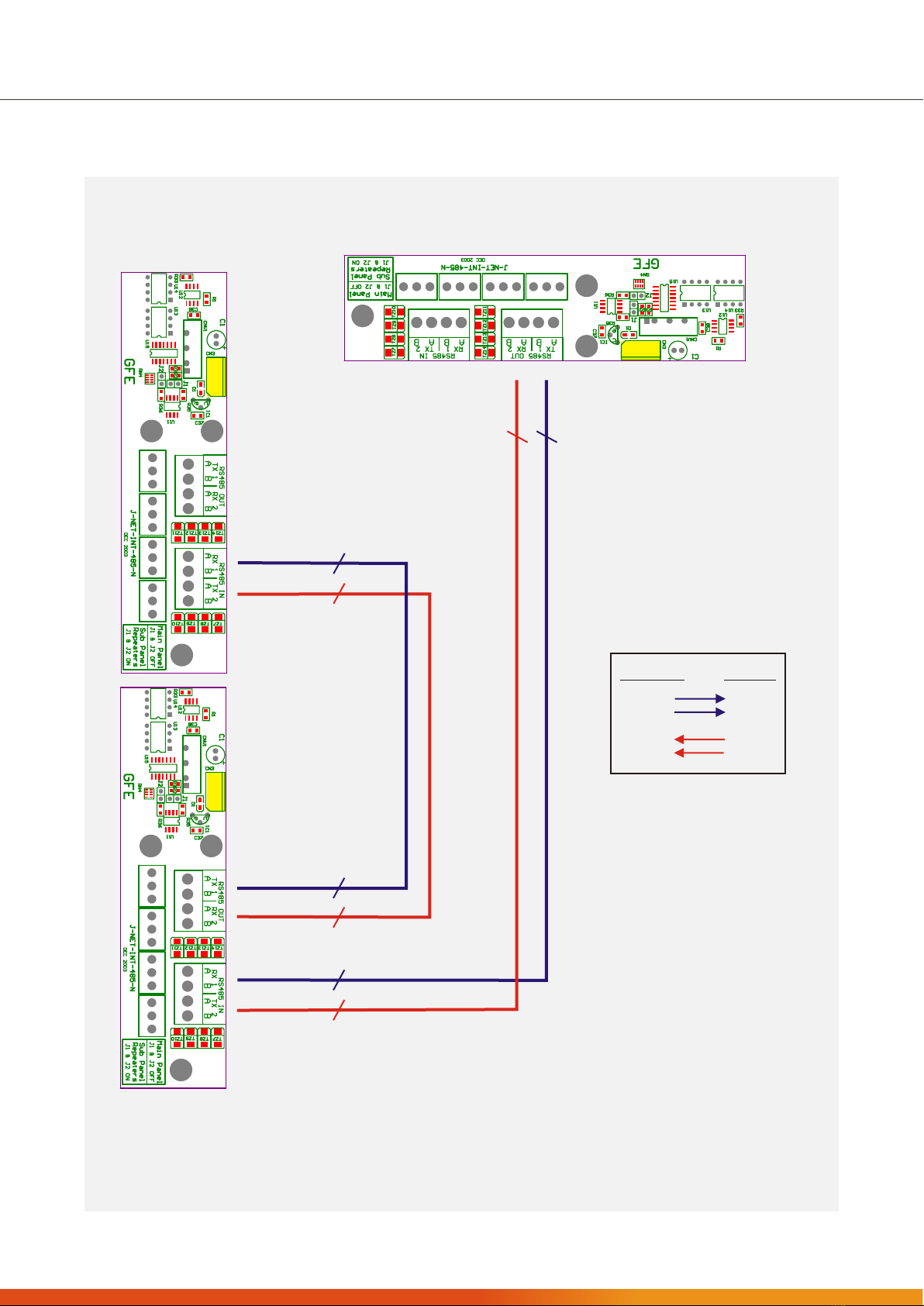
e) Connect Data Loop Cables to interface following instructions provided in this manual and
on appropriate data loop interface data sheet. Please also refer to Orion panel’s installation manual
for further details on how to integrate this Orion Ex Mini-Rep unit on a networked system.
f) Connect Power Supply. Orion Ex Mini-Rep are supplied by an external 24V DC, normally from the
control panel. Do not apply supply voltage until installation is complete.
g) Finally replace Orion Ex Mini-Rep cover onto unit’s back box using the four previously removed screws.
Before powering up the unit, verify that all connections are correctly made and that there are no open or
short circuits on any of the interconnecting wires used for both supply and data transmission.
All connections should be performed with all elements of the fire detection system unpowered.
The Repeater should be located where access to the internal components is not restricted and where the unit is
not exposed to high levels of moisture, vibration and shock.
All cables should be screened.
When using RS-232 interfaces only use cables recommended for this communicationmedia. As a general rule,
cables used for LAN (Cat 5) are suitable for this type of interfacing technology as they are widely available and
offer excellent data transmission characteristics.
Signal cables for RS485 Communication Links (twisted pair) to Repeater panels
12 AWG Signal 88202 Belden 9583 WPW999
14 AWG Signal 88402 Belden 9581 WPW995
16 AWG Signal 88602 Belden 9575 WPW991
18 AWG Signal 88802 Belden 9574 WPW975
FIRETUF FDZ1000 by Draka 2 core
PIRELLI type FP200 Gold 2 core
PIRELLI type FP-PLUS
Fibre Optic: Multi-mode Dual Core sheathed fire proof with 62,5µ/125µ fibre terminated in ST connectors.
WARNING:
WARNING:
observe ESD precautions when handling the PCBs.
Cable screen’s should only be connected at one point to the physical Earth
connection in order to avoid current loops.
Manufacturers of Fire Detection Equipment
globalfire.pt
INSTALLATION MANUAL 1.0 - 06/2015
ORION EX MINI-REP

Figure 1: ORION EX MINI-REP - Installation
Top Cable Entry
MECHANICAL DETAILS
256 mm
246 mm
75 mm
194 mm
187 mm
Rear Cable Entry
Orion Ex Mini-Rep Data Loop
Interface PCB - Stand-offs
Orion Ex Mini-Rep
Back Box - Mounting Holes
Manufacturers of Fire Detection Equipment
globalfire.pt
INSTALLATION MANUAL 1.0 - 06/2015
ORION EX MINI-REP

Figure 2: ORION EX MINI-REP - General Hardware and Connections Layout
Connect
Orion Ex Mini-Rep CON3 (Data Loop)
to corresponding interface.
+24 V DC
Ground ( 0V )
Earth
Manufacturers of Fire Detection Equipment
globalfire.pt
INSTALLATION MANUAL 1.0 - 06/2015
ORION EX MINI-REP

Figure 3: ORION EX MINI-REP - RS-232 Data Loop Interface Connections
NOTE:
When using RS-232 interfaces only one Mini-Rep will be able to
control the Orion conventional panel. All other Orion Ex Mini-Rep’s
will only be able to display system status.
Maximum distance between Panel and last Orion Ex Mini-Rep
should be 100 meters.
Connect to
cable screens
ORION EX MINI-REP
Interface 2
ORION EX MINI-REP
Interface 1
ORION Conventional Panel
Manufacturers of Fire Detection Equipment
globalfire.pt
INSTALLATION MANUAL 1.0 - 06/2015
ORION EX MINI-REP

Figure 3: ORION EX MINI-REP -Orion Panel Multi - RS-485 interface connections.
CON3
CON3
ORION EX MINI-REP
ORION EX MINI-REP
CON3
2
2
2
2
2
2
2
2
RS-485 OUT RS-485 IN
Tx1 a
Tx1 b
Rx2 a
Rx2 b
Rx1 a
Rx1 b
Tx2 a
Tx2 b
NOTES:
On Orion Panel interface JP1 and JP2
should be removed. On Orion Ex Mini-
Rep interface JP1 and JP2 should be ON.
Interface CON3 should be connected to
DATA connector (Cn3) placed on the
underside of the Orion panel main board
and to Data Loop connector (CON3) on
Orion Ex Mini-Rep board.
ORION Conventional Panel
Manufacturers of Fire Detection Equipment
globalfire.pt
INSTALLATION MANUAL 1.0 - 06/2015
ORION EX MINI-REP

THE ORION EX MINI-REP SYSTEM STATUS INDICATORS
AND CONTROL BUTTONS
STATUS
FIRE LED used to indicate any FIRE ALARM condition present on panel.
FAULT LED used to indicate any FAULT condition present on panel.
DISABLED Disabled Status LED used to indicate that the panel has features that have been disabled in
either Access Level 2 or 3 modes.
TEST This LED is active whenever panel is in TEST MODE. Only LIT when in Engineering Mode and
TEST mode has been selected.
SUPPLY Multi function indicator used to indicate the presence of supply. When in Access Level 1 this
LED is permanently lit. If in Access Level 2 (enter this mode using USER CODE) this LED will flash
at a rate of once per second. And finally if in Access Level 3 mode (enter using ENGINEERING
CODE) this LED will flash faster at a rate of once every 0,5 seconds.
SYSTEM FAULT This LED will be lit whenever there is a processor failure or corruption of the panel firmware.
Manufacturers of Fire Detection Equipment
globalfire.pt
INSTALLATION MANUAL 1.0 - 06/2015
ORION EX MINI-REP

FAULTS
SUPPLY This LED will be ON whenever the Main Supply has been removed or has dropped
below 20Volts.
BATTERY Indicates that there is low voltage level on the batteries or the battery charger circuit
has failed.
SOUNDERS If there is a conventional sounder circuit fault, the General Fault LED will be lit and the
Disable Sounders LED in the disablements section will also be lit and flashing.
EARTH When this indicator is ON there is leakage current flowing from the earth connection/
wiring and any conductor in coming into the panel.
ZONE & INPUT INDICATORS
Individual zone indicators are provided for both FIRE/ALARM and FAULT conditions.
If any of these inputs is disabled then its FAULT LED will also be used to indicate the disablement of that
particular zone/ input. The Zone/ Input disabled LED will be ON along with the Disabled status LED. Flashing
Zone Fault LED along with General fault LED indicates fault on that zone.
CONTROLS -
Some switches will only be operational at the repeater after entering the authorised user code. If the operation
of a switch is only available after succesfully entering the authorised user code it will be clearly stated in this
manual that these functions are only active at access level 2.
NOTE: If active please SILENCE INTERNAL BUZZER before entering code.
The four switches are numbered to indicate that they are used to enter digits from 1 to 4 for authorised user
code entry.
BUZZER SILENCE (1 ) At Access Level 1 this button is used to silence the panel's internal buzzer. Access level 3
used to confirm/accept changes in programming.
RESET ( 2 ) Press this button to reset the panel at access level 2.
LAMPTEST( 3 ) Press this button at access level 1 or 2 to test all LED indicators and the panel's internal
buzzer. Release when test is finished.
SOUNDERS( 4 ) Press once to activate/silence sounders. If sounders are active, for example, during a
FIRE condition or in the event of an Evacuation action, pressing this button will stop the
sounders. Auxiliary Relays are not affected by this action.
AUTHORISED USER CODE: 2244
Manufacturers of Fire Detection Equipment
globalfire.pt
INSTALLATION MANUAL 1.0 - 06/2015
ORION EX MINI-REP

EXTINGUISHING CYCLE
The extinguishing process can be controlled manually using the buttons available on the front display.
The extinguishing cycle cn be initiated manually executing the following steps:
a) In level 1, silence the internal buzzer using the INTERNAL BUZZER SILENCE button if there are any Fire or
Fault conditions which have not been acknowledged.
b) If panel is in access level 1, access level 2 by using either the access key provided or by entering the user
code 2244.
c) In order to activate the extinguishing press the ACTIVATE EXTINGUISHING button. Activation is
confirmed after the internal buzzer sounds for 1 second. Extinguishing outputs will activated
inmediately for the duration of the previously programmed extinguihing time. Sounder Circuit 1 will
also be activated. When the extinguishing cycle is initiated manually, the pre-extinguishing delay is not
obeyed.
The extinguishing cycle can be stopped once initiated by pressing the ABORT EXTINGUISHING button.
ORDER CODE
TECHNICAL SPECIFICATIONS
CONVENTIONAL MINI-REPEATER PANEL FOR ORION EX - INCLUDES 1 X RS232 INTERFACE
28 V DC nominal derived from Orion Aux. Supply O/P
40 mA
+Supply, -Supply, TX and RX
RS232, RS485, FO or TCP/IP - 1 Display & Control 3 Display Only
95% RH Non-Condensing
-10ºC to 50ºC
1.4 Kg
256 (L) x 194 (W) x 75 (H) mm
White or Red
SUPPLY VOLTAGE
SUPPLY CURRENT
CONNECTIONS
REPEATER NETWORK
MAX. HUMIDITY
OPERATING TEMPERATURE
WEIGHT
DIMENSIONS
COLOUR
ORION EX MINI-REP
Manufacturers of Fire Detection Equipment
globalfire.pt
INSTALLATION MANUAL 1.0 - 06/2015
ORION EX MINI-REP

Manufacturers of Fire Detection Equipment
globalfire.pt
INSTALLATION MANUAL 1.0 - 06/2015
ORION EX MINI-REP
GLOBAL FIRE EQUIPMENT S.A.
Sítio dos Barrabés, Armazém Nave Y, Caixa Postal 908-Z, 8150-016 São Brás de Alportel - PORTUGAL
Tel: +351 289 896 560 • Sales: sales@globalfire.pt • Technical Support: techs@globalfire.pt • www.globalfire.pt
Table of contents
Other Global Fire Equipment Fire Alarm manuals

Global Fire Equipment
Global Fire Equipment VALKYRIE AS User manual

Global Fire Equipment
Global Fire Equipment ZEOS C User manual

Global Fire Equipment
Global Fire Equipment MPX-SNDR-DG - 4 V2 User manual

Global Fire Equipment
Global Fire Equipment ORION Instruction manual

Global Fire Equipment
Global Fire Equipment JUNIOR V3 Manual

Global Fire Equipment
Global Fire Equipment ZEOS-C User manual

Global Fire Equipment
Global Fire Equipment ZEOS-AD-S User manual