TIS TERRE Series User manual

TERRE TOUCH THERMOSTAT
INSTALLATION MANUAL
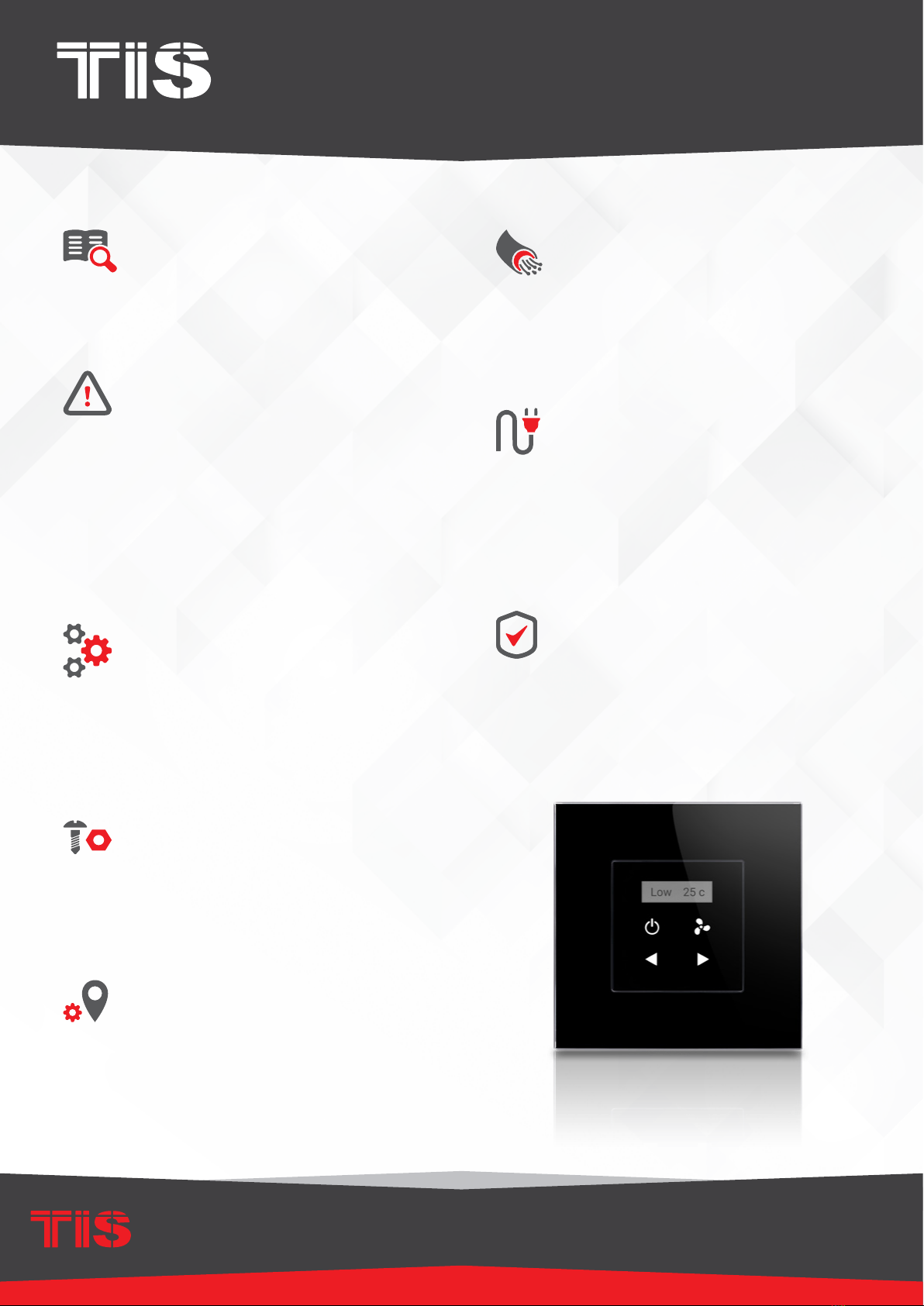
A simple 4-touch button interface to control
temperature, fan speed, oor heating, or any
other heating and cooling devices. Reminders and
alerts are displayed on a 1” high-resolution OLED
screen.
Automation Made Easy
Model: TER-ACT
PRODUCT INFORMATION
6 58921 79803 4
BARCODE (UPC-A)
PRODUCT SPECIFICATIONS
OLED Size
0.9”
Touch Active area 1.5”
Touch Type Capacitive
Input Temp sensor Resistive Temp Sensor
TIS Bus
Number of devices on 1 line Max. 64
Bus voltage 12-32 V DC
Current consumption <20 mA / 24 V DC
Protection Reverse Polarity Protection
ESD Protection
Operating and display
elements
touch buttons 4 touch buttons for AC control …
Backlight Backlight indicators
Dimensions Width × length × height 45mm × 25mm × 45mm
Housing
Materials PC anti fire / Glass in front
Internal Parts color Black & gray
IP rating IP 50
2
INSTALLATION MANUAL
MODEL: TER-ACT
TIS CONTROL LIMITED
RM 1502-p9 Easey CommBldg
253-261 Hennessy Rd Wanchai
Hong Kong
TEXAS INTELLIGENT SYSTEM LLC
SUITE# 610. 860 NORTH DOROTHY DR
RICHARDSON
TX 75081.USA
Copyright © 2020 TIS, All Rights Reserved
TIS Logo is a Registered Trademark of Texas Intelligent System LLC in the
United States of America. This company takes TIS Control Ltd. in other
countries. All of the Specifications are subject to change without notice.
www.tiscontrol.com
TERRE TOUCH THERMOSTAT
Data Cable
Use screened stranded RS485 data cable
with four twisted pairs. Congure devices in
a “Daisy Chain.”
Do not cut or terminate live data cables.
Electrical Wires
The recommended wire size for light
channels is 1.5mm - 2.5mm for loads, if you
are using the Panel Addition 3R type. The
installer should consider the total current
consumption when selecting the wires.
Warranty
There is a two-year warranty provided
by law. The hologram warranty seal and
product serial number are available on
each device.
Read Instructions
We recommend that you read this
Instruction Manual before installation.
Safety instructions
Electrical equipment should only be
installed and tted by electrically skilled
persons.
Failure to follow the instructions may cause
damage to the device and other hazards.
These instructions are an integral part of
the product and must remain with the end
customer.
Programming
This device can be tested and programmed
manually. Advanced programming
requires knowledge of the TIS Device
Search software and instruction in the TIS
advanced training courses.
Simple Installation
You can use 2 screws to install this panel
on wall; it ts on Europe round and UK
square junction box sizes.
Mounting Location
Install in a dry, indoor area with a suitable
temperature and humidity range.
3
INSTALLATION MANUAL
MODEL: TER-ACT
TIS CONTROL LIMITED
RM 1502-p9 Easey CommBldg
253-261 Hennessy Rd Wanchai
Hong Kong
TEXAS INTELLIGENT SYSTEM LLC
SUITE# 610. 860 NORTH DOROTHY DR
RICHARDSON
TX 75081.USA
Copyright © 2020 TIS, All Rights Reserved
TIS Logo is a Registered Trademark of Texas Intelligent System LLC in the
United States of America. This company takes TIS Control Ltd. in other
countries. All of the Specifications are subject to change without notice.
www.tiscontrol.com
TERRE TOUCH THERMOSTAT
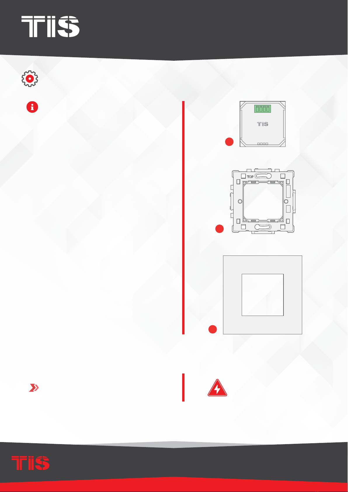
Turn off TIS power supply.
The TIS Terre wall switch consists of
three main components for installation; a
base module unit (g. 1), a wall base (g
2), and a top interface cover (g 3).
The top cover comes in a variety of
materials, colors, and a customized
combination of 1-4 gangs.
1
INSTALLATION STEPS
1
2
3
WARNING! HIGH VOLTAGE

4
INSTALLATION MANUAL
MODEL: TER-ACT
TIS CONTROL LIMITED
RM 1502-p9 Easey CommBldg
253-261 Hennessy Rd Wanchai
Hong Kong
TEXAS INTELLIGENT SYSTEM LLC
SUITE# 610. 860 NORTH DOROTHY DR
RICHARDSON
TX 75081.USA
Copyright © 2020 TIS, All Rights Reserved
TIS Logo is a Registered Trademark of Texas Intelligent System LLC in the
United States of America. This company takes TIS Control Ltd. in other
countries. All of the Specifications are subject to change without notice.
www.tiscontrol.com
TERRE TOUCH THERMOSTAT
INSTALLATION STEPS
Insert the Terre Module inside the Terre
Base by pushing it inside. Please note
the “TOP” label on the base in order to
insert the module correctly.
2
3Connect the TIS-BUS Cable to the
connector, and insert it into the Terre
module.
Cat5e
5
INSTALLATION MANUAL
MODEL: TER-ACT
TIS CONTROL LIMITED
RM 1502-p9 Easey CommBldg
253-261 Hennessy Rd Wanchai
Hong Kong
TEXAS INTELLIGENT SYSTEM LLC
SUITE# 610. 860 NORTH DOROTHY DR
RICHARDSON
TX 75081.USA
Copyright © 2020 TIS, All Rights Reserved
TIS Logo is a Registered Trademark of Texas Intelligent System LLC in the
United States of America. This company takes TIS Control Ltd. in other
countries. All of the Specifications are subject to change without notice.
www.tiscontrol.com
TERRE TOUCH THERMOSTAT
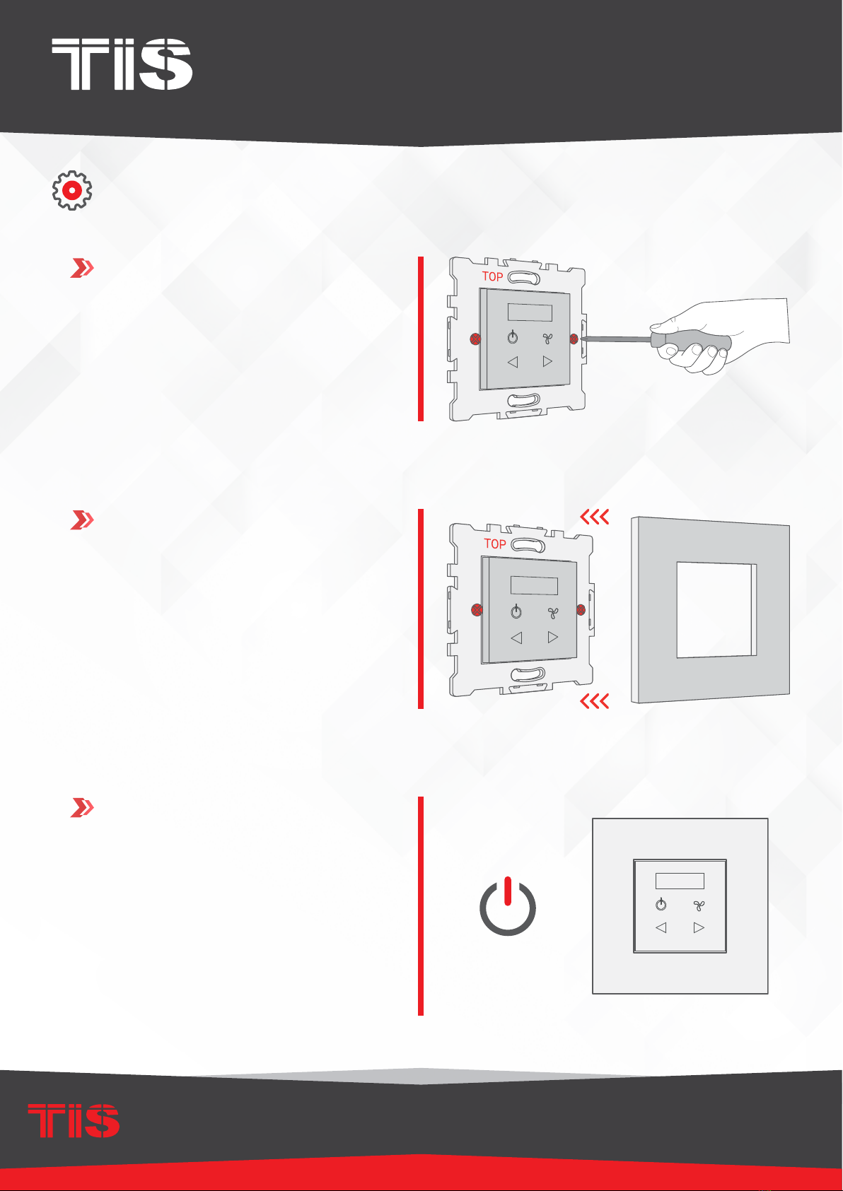
INSTALLATION STEPS
Low 25 c
Install the Terre base into the wall, and x
it with 2 screws.
5
4
6
Install the Terre cover on the Terre base.
Turn the power supply ON. The Terre
panel should turn on.

6
INSTALLATION MANUAL
MODEL: TER-ACT
TIS CONTROL LIMITED
RM 1502-p9 Easey CommBldg
253-261 Hennessy Rd Wanchai
Hong Kong
TEXAS INTELLIGENT SYSTEM LLC
SUITE# 610. 860 NORTH DOROTHY DR
RICHARDSON
TX 75081.USA
Copyright © 2020 TIS, All Rights Reserved
TIS Logo is a Registered Trademark of Texas Intelligent System LLC in the
United States of America. This company takes TIS Control Ltd. in other
countries. All of the Specifications are subject to change without notice.
www.tiscontrol.com
TERRE TOUCH THERMOSTAT
INSTALLATION STEPSINSTALLATION STEPS
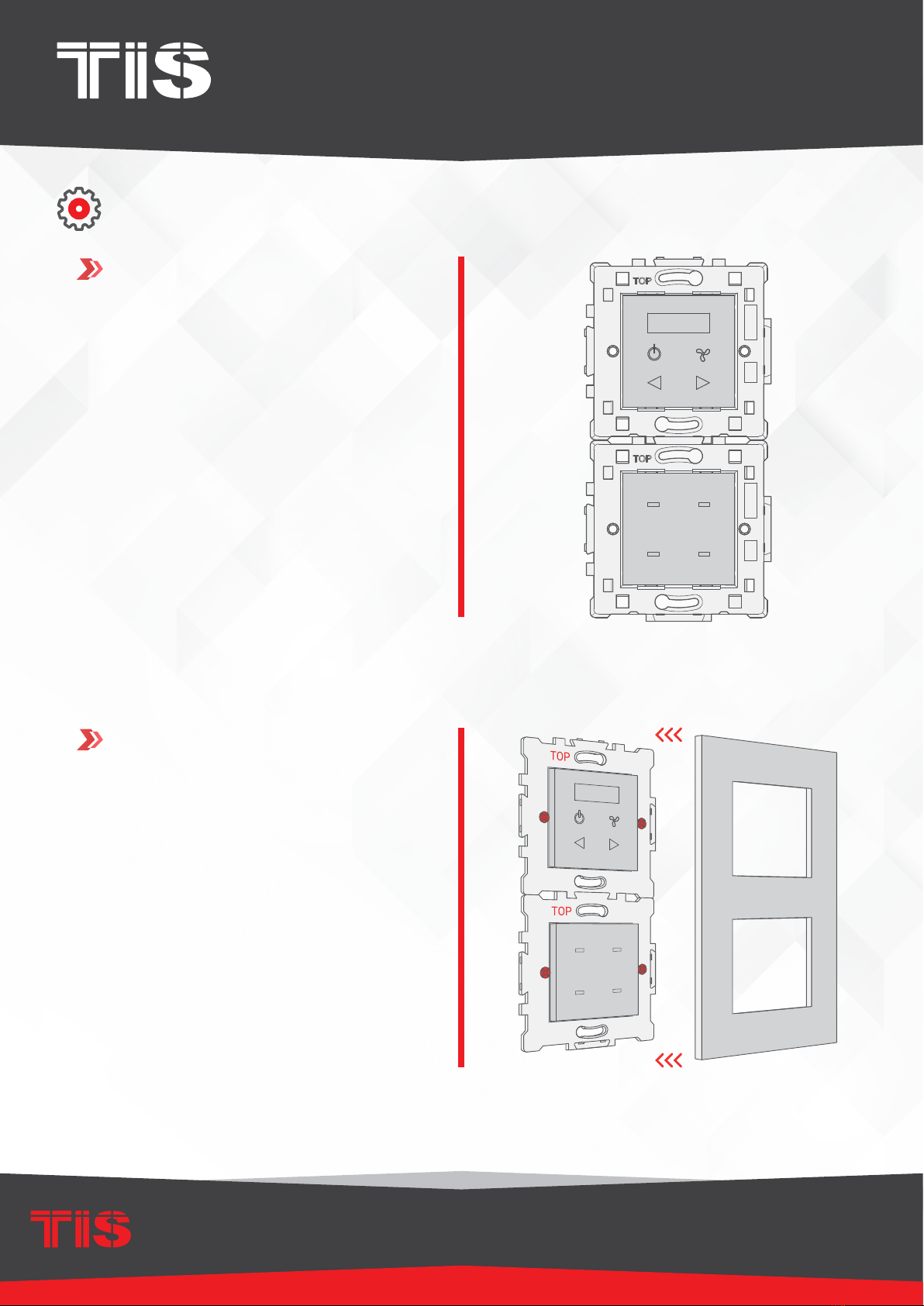
The Terre series is modular, so you can
combine 2 to 4 different Terre panels,
switches, or plugs together vertically or
horizontally. To do so, follow these steps:
1Combine 2, 3, or 4 bases together
horizontally or vertically. Please note that
all “TOP” labels should always be in the
correct position.
▸
The following picture shows how to
install 2 bases horizontally.
▸
The following picture shoes how to
install 2 bases vertically.
7
INSTALLATION MANUAL
MODEL: TER-ACT
TIS CONTROL LIMITED
RM 1502-p9 Easey CommBldg
253-261 Hennessy Rd Wanchai
Hong Kong
TEXAS INTELLIGENT SYSTEM LLC
SUITE# 610. 860 NORTH DOROTHY DR
RICHARDSON
TX 75081.USA
Copyright © 2020 TIS, All Rights Reserved
TIS Logo is a Registered Trademark of Texas Intelligent System LLC in the
United States of America. This company takes TIS Control Ltd. in other
countries. All of the Specifications are subject to change without notice.
www.tiscontrol.com
TERRE TOUCH THERMOSTAT
INSTALLATION STEPSINSTALLATION STEPS
2
3
Insert the Terre panels, switches, or plugs
into the base.
Cover with the Terre 2-, 3-, or 4-gang
covers according to the combination.

8
INSTALLATION MANUAL
MODEL: TER-ACT
TIS CONTROL LIMITED
RM 1502-p9 Easey CommBldg
253-261 Hennessy Rd Wanchai
Hong Kong
TEXAS INTELLIGENT SYSTEM LLC
SUITE# 610. 860 NORTH DOROTHY DR
RICHARDSON
TX 75081.USA
Copyright © 2020 TIS, All Rights Reserved
TIS Logo is a Registered Trademark of Texas Intelligent System LLC in the
United States of America. This company takes TIS Control Ltd. in other
countries. All of the Specifications are subject to change without notice.
www.tiscontrol.com
TERRE TOUCH THERMOSTAT
To use the Terre with Panel Addition, you should select Model TER-ACT-A and follow these
steps:
1
2
Remove the back Terre part.
Insert the Terre panel into the Terre base.
INSTALLATION STEPS

9
INSTALLATION MANUAL
MODEL: TER-ACT
TIS CONTROL LIMITED
RM 1502-p9 Easey CommBldg
253-261 Hennessy Rd Wanchai
Hong Kong
TEXAS INTELLIGENT SYSTEM LLC
SUITE# 610. 860 NORTH DOROTHY DR
RICHARDSON
TX 75081.USA
Copyright © 2020 TIS, All Rights Reserved
TIS Logo is a Registered Trademark of Texas Intelligent System LLC in the
United States of America. This company takes TIS Control Ltd. in other
countries. All of the Specifications are subject to change without notice.
www.tiscontrol.com
TERRE TOUCH THERMOSTAT
4
5
Connect any panel addition type that
supports the Terre panel.
Follow the connection diagram as per the
type of panel addition.
O-OFF
I-ON
MCB
GND(white-orange)&(white-brown)
D-(white-green)&(white-blue)
D+(blue-green)
+24V(brown-orange)
Cat5e connection
1.5 mm Electric Cable
1.5 mm Electric Cable
2.5 mm Electric Cable
PANEL ADDITION
3 Output Relay 5 Amp
Model : ADD-3R-5A
TIS BUS Input : 45-75mA/24V DC
Output Current : 3A220VAC
COM OUT3 OUT2 OUT1 COM
www.tissmarthome.com
D- +24V
GND D+
TER-ACT-A
Connect To L
Connect To N
Cat5e
To the TIS BUS Network
INSTALLATION STEPS
3Connect the back part to the panel again.

10
INSTALLATION MANUAL
MODEL: TER-ACT
TIS CONTROL LIMITED
RM 1502-p9 Easey CommBldg
253-261 Hennessy Rd Wanchai
Hong Kong
TEXAS INTELLIGENT SYSTEM LLC
SUITE# 610. 860 NORTH DOROTHY DR
RICHARDSON
TX 75081.USA
Copyright © 2020 TIS, All Rights Reserved
TIS Logo is a Registered Trademark of Texas Intelligent System LLC in the
United States of America. This company takes TIS Control Ltd. in other
countries. All of the Specifications are subject to change without notice.
www.tiscontrol.com
TERRE TOUCH THERMOSTAT
INSTALLATION STEPS
Install the Terre base into the wall, and x
it with 2 screws.
7
6
8
Install the Terre cover on the Terre base.
Turn the power supply ON. The Terre
panel should turn on.
IN
29
25

11
INSTALLATION MANUAL
MODEL: TER-ACT
TIS CONTROL LIMITED
RM 1502-p9 Easey CommBldg
253-261 Hennessy Rd Wanchai
Hong Kong
TEXAS INTELLIGENT SYSTEM LLC
SUITE# 610. 860 NORTH DOROTHY DR
RICHARDSON
TX 75081.USA
Copyright © 2020 TIS, All Rights Reserved
TIS Logo is a Registered Trademark of Texas Intelligent System LLC in the
United States of America. This company takes TIS Control Ltd. in other
countries. All of the Specifications are subject to change without notice.
www.tiscontrol.com
TERRE TOUCH THERMOSTAT
GND(white-orange)&(white-brown)
D-(white-green)&(white-blue)
D+(blue-green)
+24V(brown-orange)
Cat5e connection
1/L 2/M 3/H 4/L 5/M 6/H 7/L 8/M
1/L 2/M
TIS-BUS
GND D- D+ +24V
PRG
9/H 10/L 11/M 12/H
3/H
4/L 5/M 7/L 8/M 10/L 11/M
6/H 9/H 12/H
A B CD
VLC-12CH-10A WARNING! HIGH VOLTAGE!
To the TIS BUS Network
Cat5e
PAIRING (MANUAL PROGRAMMING)
FCU PROGRAMMING
1To program the FCU to any wall
thermostat panel, press and hold the rst
Channel L (LOW) button for 6 seconds.
The LED indicator of the pressed button
will start blinking,
6”
On the Terre panel, turn the AC ON.
2
IN
29
25
IN
29
25
Test your air conditioning by changing the
fan speed from low to medium to high.
Your relay should respond accordingly.
3
12
INSTALLATION MANUAL
MODEL: TER-ACT
TIS CONTROL LIMITED
RM 1502-p9 Easey CommBldg
253-261 Hennessy Rd Wanchai
Hong Kong
TEXAS INTELLIGENT SYSTEM LLC
SUITE# 610. 860 NORTH DOROTHY DR
RICHARDSON
TX 75081.USA
Copyright © 2020 TIS, All Rights Reserved
TIS Logo is a Registered Trademark of Texas Intelligent System LLC in the
United States of America. This company takes TIS Control Ltd. in other
countries. All of the Specifications are subject to change without notice.
www.tiscontrol.com
TERRE TOUCH THERMOSTAT
PAIRING (MANUAL PROGRAMMING)
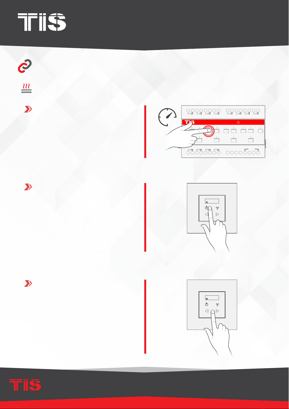
HVAC PROGRAMMING
1Press the PRG button of the HVAC
Module for 6 seconds until the green LED
turns on and is steady.
Test your air conditioning by changing
the mood, Heat/Cool, and fan speed from
low to medium to high. HVAC module
should respond accordingly.
3
HVAC6-3-A-T
Low Med
Cool Heat
PRG
TIS-BUS
GND D+ +24V
D-
High
AUX
MODE FAN
TEMP
VAV
GND 0-10V T- T+
Com Cool Heat Aux Low Med High
Com
6”
On Terre panel, turn the AC ON.
2
IN
29
25
Low 25 c
13
INSTALLATION MANUAL
MODEL: TER-ACT
TIS CONTROL LIMITED
RM 1502-p9 Easey CommBldg
253-261 Hennessy Rd Wanchai
Hong Kong
TEXAS INTELLIGENT SYSTEM LLC
SUITE# 610. 860 NORTH DOROTHY DR
RICHARDSON
TX 75081.USA
Copyright © 2020 TIS, All Rights Reserved
TIS Logo is a Registered Trademark of Texas Intelligent System LLC in the
United States of America. This company takes TIS Control Ltd. in other
countries. All of the Specifications are subject to change without notice.
www.tiscontrol.com
TERRE TOUCH THERMOSTAT
PAIRING (MANUAL PROGRAMMING)
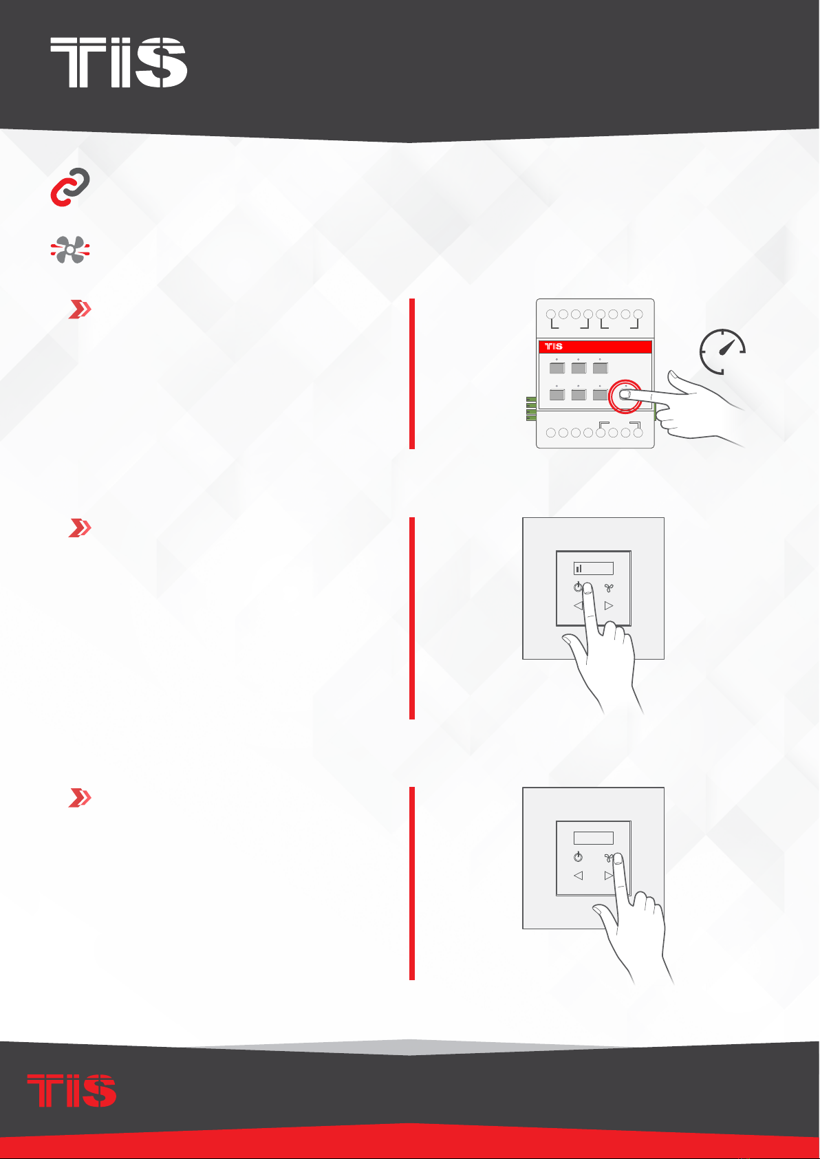
FLOOR HEATING PROGRAMMING
1Press any button on any channel of a
relay or dimmer module for 6 seconds so
that the LED indicator light of that button
starts blinking.
Test your oor heating by changing
the temperature, relay should respond
accordingly.
3
GND(white-orange)&(white-brown)
D-(white-green)&(white-blue)
D+(blue-green)
+24V(brown-orange)
Cat5e connection
1/L 2/M 3/H 4/L 5/M 6/H 7/L 8/M
1/L 2/M
TIS-BUS
GND D- D+ +24V
PRG
9/H 10/L 11/M 12/H
3/H
4/L 5/M 7/L 8/M 10/L 11/M
6/H 9/H 12/H
A B CD
VLC-12CH-10A WARNING! HIGH VOLTAGE!
To the TIS BUS Network
Cat5e
6”
On Terre oor heater page, turn the oor
heating ON. (see page 14)
2
Floor IN
25
35
Floor IN
25
35
14
INSTALLATION MANUAL
MODEL: TER-ACT
TIS CONTROL LIMITED
RM 1502-p9 Easey CommBldg
253-261 Hennessy Rd Wanchai
Hong Kong
TEXAS INTELLIGENT SYSTEM LLC
SUITE# 610. 860 NORTH DOROTHY DR
RICHARDSON
TX 75081.USA
Copyright © 2020 TIS, All Rights Reserved
TIS Logo is a Registered Trademark of Texas Intelligent System LLC in the
United States of America. This company takes TIS Control Ltd. in other
countries. All of the Specifications are subject to change without notice.
www.tiscontrol.com
TERRE TOUCH THERMOSTAT
USER MANUAL
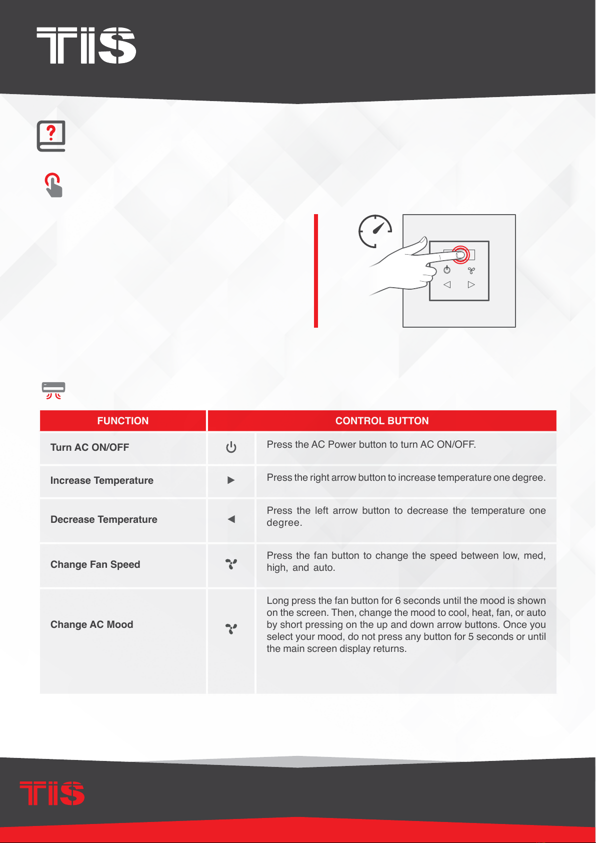
To change between the AC page and
the oor heater page, press and hold the
OLED screen for 3 seconds.
SHIFTING BETWEEN AC & FLOOR HEATING PAGE
IN
29
25
CONTROLLING AIR CONDITIONING
FUNCTION CONTROL BUTTON
Turn AC ON/OFF Press the AC Power button to turn AC ON/OFF.
Increase Temperature Press the right arrow button to increase temperature one degree.
Decrease Temperature Press the left arrow button to decrease the temperature one
degree.
Change Fan Speed Press the fan button to change the speed between low, med,
high, and auto.
Change AC Mood
Long press the fan button for 6 seconds until the mood is shown
on the screen. Then, change the mood to cool, heat, fan, or auto
by short pressing on the up and down arrow buttons. Once you
select your mood, do not press any button for 5 seconds or until
the main screen display returns.
3”
15
INSTALLATION MANUAL
MODEL: TER-ACT
TIS CONTROL LIMITED
RM 1502-p9 Easey CommBldg
253-261 Hennessy Rd Wanchai
Hong Kong
TEXAS INTELLIGENT SYSTEM LLC
SUITE# 610. 860 NORTH DOROTHY DR
RICHARDSON
TX 75081.USA
Copyright © 2020 TIS, All Rights Reserved
TIS Logo is a Registered Trademark of Texas Intelligent System LLC in the
United States of America. This company takes TIS Control Ltd. in other
countries. All of the Specifications are subject to change without notice.
www.tiscontrol.com
TERRE TOUCH THERMOSTAT
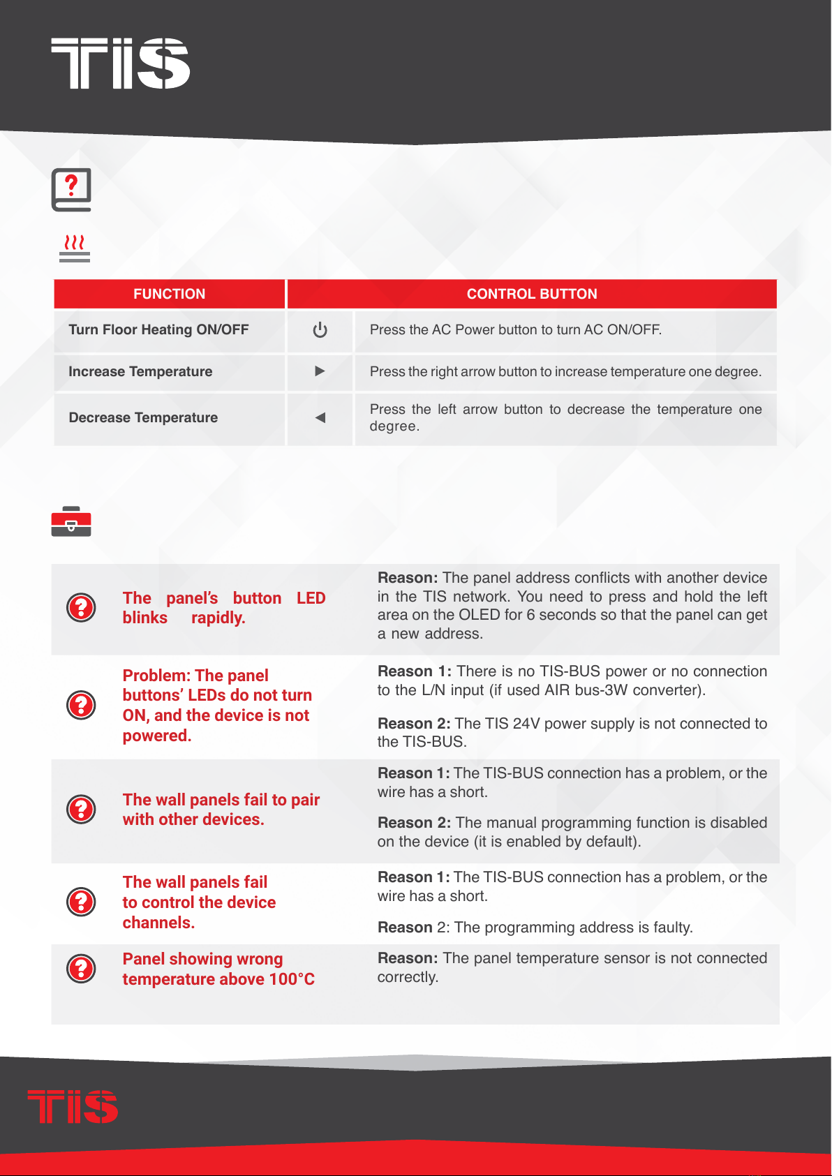
TROUBLESHOOTING
The panel’s button LED
blinks rapidly.
Reason: The panel address conicts with another device
in the TIS network. You need to press and hold the left
area on the OLED for 6 seconds so that the panel can get
a new address.
Problem: The panel
buttons’ LEDs do not turn
ON, and the device is not
powered.
Reason 1: There is no TIS-BUS power or no connection
to the L/N input (if used AIR bus-3W converter).
Reason 2: The TIS 24V power supply is not connected to
the TIS-BUS.
The wall panels fail to pair
with other devices.
Reason 1: The TIS-BUS connection has a problem, or the
wire has a short.
Reason 2: The manual programming function is disabled
on the device (it is enabled by default).
The wall panels fail
to control the device
channels.
Reason 1: The TIS-BUS connection has a problem, or the
wire has a short.
Reason 2: The programming address is faulty.
Panel showing wrong
temperature above 100°C
Reason: The panel temperature sensor is not connected
correctly.
FUNCTION CONTROL BUTTON
Turn Floor Heating ON/OFF Press the AC Power button to turn AC ON/OFF.
Increase Temperature Press the right arrow button to increase temperature one degree.
Decrease Temperature Press the left arrow button to decrease the temperature one
degree.
CONTROLLING FLOOR HEATING
USER MANUAL
Other manuals for TERRE Series
1
This manual suits for next models
1
Table of contents
Other TIS Thermostat manuals


Popular Thermostat manuals by other brands


Viconics
Viconics PIR Ready7 VT76x7 Series Integration manual

Namiba Terra
Namiba Terra Biostat 1000 instructions

TOTALINE
TOTALINE P474-1100RF owner's manual

Honeywell
Honeywell FocusPRO TH5000 Series operating manual

blossom-ic
blossom-ic HERADIRECT+ Assembly instructions

Siemens
Siemens TH 192 S installation instructions


