TissueLink Aquamantys System User manual

i
SERVICE MANUAL

_______________________________________________________________________________
ii
Software Version 1.10
SERVICE MANUAL

_______________________________________________________________________________
iii
Foreword
The Aquamantys™ Pump Generator is for use only by qualified
medical personnel properly trained in the use of electrosurgical
equipment, technology and techniques. This Service Manual is a
guide for maintaining and servicing the Aquamantys Pump Generator.
Additional clinical usage information is available in the Aquamantys
Pump Generator Users Guide and in the Instructions for Use which
accompany individual Aquamantys Disposable Bipolar Devices which
are designed to be used as a part of the Aquamantys System.
Federal (USA) Law restricts this device to sale, distribution or use by or on
the order of a physician.
Equipment covered in this manual:
Aquamantys™Pump Generator
Nominal
Supply Voltage
Tissuelink
Model #
100V 50/60Hz 40-401-1
115V 50/60Hz 40-402-1
230V 50/60Hz 40-403-1
For information call:
TissueLink Medical, Inc.
One Washington Center
Suite 400
Dover, NH 03820 USA
www.tissuelink.com or www.aquamantys.com
Customer Service:
Tel: 866.777.9400
+1.603.742.1515 (outside the U.S.)
Fax: 866.222.0900
+1.603.742.1488 (outside the U.S.)
Authorized European Representative:
WMDE
Kruisstraat 108
6461 HC Kerkrade
The Netherlands
Tel: 31.45.535.06.25
Fax: 31.45.535.06.26
Manufactured for TissueLink Medical by:
Söring GmbH
Medizintechnik
Justus-von-Liebig-Ring 2
25451 Quickborn, Germany
Precaution:

_______________________________________________________________________________
iv
Table of Contents
Foreword ...............................................................................................................iii
Table of Contents .................................................................................................. iv
List of Tables and Figures......................................................................................... v
Section 1 - Introduction ........................................................................................... 1-1
General Description .............................................................................................. 1-1
RF Power ............................................................................................................ 1-1
Simultaneous RF Power and Saline Delivery............................................................. 1-1
Saline Flow Rate Setting ....................................................................................... 1-1
Priming ............................................................................................................... 1-1
Section 2 - Controls, Indicators, and Receptacles ........................................................ 2-1
Symbols ............................................................................................................. 2-5
Section 3 - Technical Specifications .......................................................................... 3-1
Performance Characteristics .................................................................................. 3-1
Standards and IEC Classifications........................................................................... 3-4
Output Characteristics .......................................................................................... 3-5
Accessories......................................................................................................... 3-8
Connectors ......................................................................................................... 3-8
Section 4 - Circuitry Description................................................................................ 4-1
Description of unit components.............................................................................. 4-2
Section 5 - Testing and Servicing Safety .................................................................... 5-1
Section 6 - Maintenance and Repair........................................................................... 6-1
Responsibility of the Manufacturer ......................................................................... 6-1
Routine Maintenance ............................................................................................ 6-1
Returning the Aquamantys™ Pump Generator for Service........................................... 6-7
Section 7 - Troubleshooting...................................................................................... 7-1
General Troubleshooting Guidelines ........................................................................ 7-1
Troubleshooting Malfunctions ................................................................................ 7-2
Responding to Alarms........................................................................................... 7-6
Section 8 - Error Codes and Error Handling ................................................................. 8-1
Error display during the self-test............................................................................. 8-1
Error handling ...................................................................................................... 8-1
MPU1 Error Codes:............................................................................................... 8-3
Section 9 - Service Access....................................................................................... 9-1
Opening the unit .................................................................................................. 9-1
Removing the power supply unit ............................................................................ 9-2
Removing the rear panel........................................................................................ 9-2
Removing the cooler fan unit ................................................................................. 9-3
Removing the pump head and the drive unit ............................................................ 9-3
Section 10 - Schematic Diagrams............................................................................ 10-1
Section 11 - Warranty ........................................................................................... 11-1

_______________________________________________________________________________
v
List of Tables and Figures
Figure 2-1. Front Panel ............................................................................................ 2-1
Figure 2-2. Rear Panel ............................................................................................. 2-1
Figure 3-1. Output Voltage vs. Power Setting ............................................................. 3-6
Figure 3-2. Output Power vs. Resistance.................................................................... 3-6
Figure 3-3. Saline Flow Rate vs. Power Setting ........................................................... 3-7
Figure 3-4. Power Setting Characteristics at rated load ................................................ 3-7
Figure 4-1. General Block Diagram ............................................................................ 4-1
Figure 4-2. Power Supply Block Diagram.................................................................... 4-4
Figure 4-3. RF Generator Block Diagram..................................................................... 4-6
Figure 4-4. Display Board Block Diagram .................................................................... 4-7
Table 6-1. Leakage Current and PE Conductor Limits ................................................... 6-2
Figure 6-1. Manual Activation of Aquamantys RF Output ............................................. 6-2
Figure 6-2. Pump Head Guide Alignment .................................................................... 6-2
Figure 6-3. Adjusting the Flow Rate Setting................................................................ 6-4
Table 6-2. Flow Rate vs Pump Shaft Revolutions Limits ............................................... 6-5
Figure 6-4. Initiating the Priming Sequence................................................................. 6-6
Table 6-3. Fuse Ratings ........................................................................................... 6-7
Table 7-1. Troubleshooting....................................................................................... 7-2
Table 8-1. Error Display ........................................................................................... 8-1
Table 8-2. Error Code Descriptions ............................................................................ 8-2
Table 8-3. MPU1 Error Display.................................................................................. 8-3
Table 8-4. MPU1 Error Code Description .................................................................... 8-4
Figure 9-1. Floor Panel Removed ............................................................................... 9-1
Figure 9-2. Power Supply Removed ........................................................................... 9-1
Figure 9-3. Power Supply......................................................................................... 9-2
Figure 9-4. Rear Panel Removed................................................................................ 9-2
Figure 10-1. Supply_TL1 Schematic ........................................................................ 10-1
Figure 10-2. Power Supply: Voltage Regulators, Output Stages Schematic ................... 10-2
Figure 10-3. Power Supply: U1 & U2 Voltage Regulators & Current Limiters Schematic . 10-3
Figure 10-4. Power Supply: Safety Circuits and Analog Conversion Schematic.............. 10-4
Figure 10-5. RF Generator: Output Stage, Output Filter Overload Protection Schematic.. 10-5
Figure 10-6. RF Generator: RF and Pulse Oscillator, Analog Interface Schematic ........... 10-6
Figure 10-7. RF Generator: Power and Current Limiters Schematic .............................. 10-7
Figure 10-8. MPU0: Power Supply, RF Generator Control Schematic ........................... 10-8
Figure 10-9. MPU1: RF Output Control, System Monitoring Schematic ........................ 10-9
Figure 10-10. System Monitoring: RF Power Measuring Schematic............................ 10-10
Figure 10-11. System Monitoring: Hand Switch Recog., Analog Control Schematic ..... 10-11
Figure 10-12. System Monitoring: Hand Switch Test Xfmr Schematic........................ 10-12
Figure 10-13. Output Control: RF Output, Power Sense Xfmrs Schematic .................. 10-13
Figure 10-14. Sound Output, Master Memory, Clock, I²C Schematic ......................... 10-14
Figure 10-15. Display Board Schematic.................................................................. 10-15

_______________________________________________________________________________
1-1
Section 1 - Introduction
General Description
The Aquamantys™ Bipolar Pump Generator is an electrosurgical
generator with a rotary peristaltic pump which is for use only with
Aquamantys single-use disposable bipolar devices for concurrent
delivery of radio-frequency energy with saline for hemostatic sealing
of blood vessels in soft tissue and bone.
RF Power
The Aquamantys Pump Generator delivers bipolar RF power with
power settings in 5 watt increments in the range of 20 to 100 watts,
and 10 watt increments in the range of 100 to 200 watts. At higher
tissue resistances the unit senses the high resistance and reduces
the RF power output, independent of the front panel setting, to a
level which prevents arcing or cutting.
Simultaneous RF Power and Saline Delivery
The Aquamantys Pump Generator simultaneously delivers RF power
and saline to an Aquamantys disposable bipolar device when the
device is properly connected to the unit and the activation button on
the device is depressed. The Pump Generator is for use only with
Aquamantys single-use disposable bipolar devices.
Saline Flow Rate Setting
The saline flow rate setting is determined based on the power setting
and the selection of one of three possible flow rate settings: low,
medium and high. The three possible saline flow rates for each
power setting are preset automatically in order to provide the optimal
saline flow for a given power setting.
Priming
The Aquamantys Pump Generator has a convenient one touch
priming function which automatically primes the Aquamantys
disposable bipolar device with saline prior to use after the device has
been correctly connected to the unit. This function is activated by
pressing the “START PRIME” button on the unit.
Precaution: The “Start Prime” button activates and deactivates the timed priming cycle.
Pressing the button a second time will immediately stop the priming cycle.
Pressing the button a third time will reset the timer and restart the priming
cycle from the beginning.

_______________________________________________________________________________
2-1
Section 2 - Controls, Indicators, and Receptacles
This section contains information about the front and rear panels,
including all controls, indicators, receptacles, and the fuse drawer.
Figure 2-1. Front Panel
Figure 2-2. Rear Panel
3
1
2 4 5
6 7 8
10
9
11

_______________________________________________________________________________
2-2
1Power On/Off Switch
The main power On/Off switch is located at the bottom left
corner of the front panel on the Aquamantys Pump Generator.
The unit is switched on by pressing the top portion of the
switch marked “⏐”. The switch will be illuminated green when
it is on.
The unit is switched off by pressing the bottom portion of the
switch marked “Ο”. It is recommended that the unit be
switched off when it is not intended to be use for an extended
period of time.
2RF Power Indicator
This indicator displays the power setting numerically in watts.
Additionally, this indicator is used to display errors, in which
case the display will show “Err” and blink alternately with a
special error code number(s).
3 Aquamantys™ Disposable Bipolar Device Receptacle
This plug receptacle is used to connect a 3-pin plug of an
Aquamantys disposable bipolar device to the Aquamantys
Pump Generator.
4Start Prime Button
This button activates and deactivates the timed priming cycle.
Pressing this button once automatically primes the Aquamantys
disposable bipolar device with saline prior to use. The pump will
operate for a preset time period to prime the Aquamantys
device. After the time period is complete, the pump shuts off
automatically.
Precautions: Priming is required to avoid RF power activation without saline. The
Aquamantys disposable bipolar device is primed when saline drips from each
of the two tips of the device. Failure to prime the device may result in RF
power activation without saline. Activation without saline may result in
charring or damage to the electrodes of the device lead to a decrease in the
hemostatic effectiveness of the device.
The “Start Prime” button activates and deactivates the timed priming cycle.
Pressing the button a second time will immediately stop the priming cycle.
Pressing the button a third time will reset the timer and restart the priming
cycle from the beginning.
5 Priming Underway Indicator
This indicator will be illuminated during the priming cycle and
turn off when the priming cycle is complete.
6 Flow Rate Setting Indicators
These indicators corresponding to a saline flow rate setting of
LOW, MEDIUM or HIGH. One of these three indicators will be
illuminated when a saline flow rate setting is selected.

_______________________________________________________________________________
2-3
7 Flow Rate Setting Buttons
These buttons control the saline flow rate. Pressing one of
these three buttons selects the flow rate setting of either
LOW MEDIUM or HIGH for each respective power
setting. The MEDIUM flow rate setting is automatically
selected as the default setting if no setting is manually
selected.
8 Saline Pump
This is a rotary peristaltic pump. A special pump segment is
attached to the saline delivery tubing of each Aquamantys
disposable bipolar device is designed to operate with the pump
head of the pump. The pump segment is loaded into this
pump head prior to operation of the device.
Precaution: Only the pump segment portion of the saline delivery tubing of the
Aquamantys disposable bipolar device should be loaded into the pump
head. Use of any other portion of the saline delivery tubing of the device or
any other tubing in this pump may damage the saline delivery tubing and/or
the pump. Incorrect insertion of the pump segment may also result in RF
power activation without saline. Activation without saline may result in
charring or damage to the electrodes of the device lead to a decrease in the
hemostatic effectiveness of the device.
Always close the pump head prior to priming or device activation. Always
allow the pump head rotor to come to a complete stop prior to opening the
pump head. Do not attempt to load or adjust the positioning of the pump
segment of the Aquamantys disposable bipolar devices in the pump head
while the pump head rotor is turning. Fingers or loose clothing could be
caught in the pump rollers.
9RF Power Setting Buttons
These buttons control the RF power setting. Press the U
button to increase the RF power. Press the Vbutton to
decrease the RF power.
10 RF Power Activation Indicator
This indicator will illuminate blue when RF power is activated.
11 Aquamantys™ Quick Reference Guide Pullout Tray
The Aquamantys Quick Reference Guide provides basic set-up
and operating instructions and illustrations for the Aquamantys
System.
12 Loudspeaker
13 Volume Control Knob
This knob controls the volume of the tone that will sound
when the RF power is activated (RF power activation tone).
To increase the volume of the RF power activation tone, turn
the knob clockwise. To decrease the volume of the RF power
activation tone, turn the knob counterclockwise. The tone
cannot be silenced.
Warning: Do not place adhesive tape or any other muffling device over the
loudspeaker.

_______________________________________________________________________________
2-4
14 Name Plate
This plate specifies the model number, serial number, nominal
line voltages, frequency, current and fuse rating information of
the Aquamantys Pump Generator.
15 Fuse Drawer
This fuse drawer contains two fuses. The Aquamantys Pump
Generator Service Manual contains information for changing
fuses.
16 Power Cord Receptacle
This plug receptacle is used to connect the main power cord
to the Aquamantys Pump Generator. The power cord should
only be connected to a source of power corresponding to that
listed on the Name Plate.
17 Equipotential Grounding Lug Connector
This lug connector is used to connect the Aquamantys Pump
Generator to earth ground.
_______________________________________________________________________________
2-5
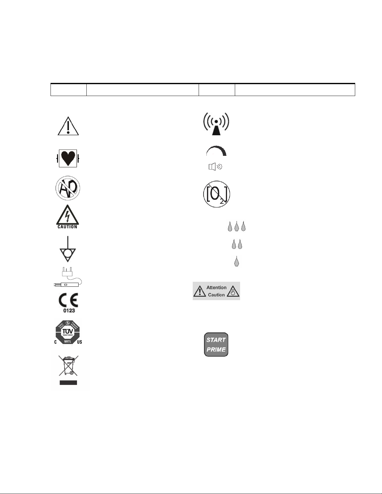
Symbols
Several symbols appear on the Aquamantys Pump Generator front panel, rear panel,
and pump head.
Symbol Indicates Symbol Indicates
Defibrillation-Proof
Type CF Applied Part
ATTENTION – Consult
accompanying documents
Bipolar Device
DANGER Explosion risk if used
with flammable anesthetics.
To reduce the risk of electric
shock, do not remove the cover.
Refer servicing to qualified
personnel.
Equipotential grounding lug
This equipment intentionally supplies
non-ionizing RF energy for physiologic
effect
Volume control of RF power
activation tone.
Do not operate in oxygen-enriched
environments
CE Mark
TUV NRTL Mark
Caution: Moving Parts – Risk of Injury.
This equipment has passed
water-ingress testing
IPX1
High setting for saline flow rate
Medium setting for saline flow rate
Low setting for saline flow rate
High
Medium
Low
Activates/deactivates device
priming sequence
Do not discard in trash. Electronic
equipment should be disposed of
in an appropriate manner.

_______________________________________________________________________________
3-1
Section 3 - Technical Specifications
Performance Characteristics
General
Output Configuration Isolated output
Cooling Internal fan, natural convection on outside
of chassis
Display Three (3) digital seven-segment displays:
0.55 inches (1.4 cm) each
Dimensions and Weight
Width 12.2 inches (31.0 cm)
Depth 15.2 inches (38.5 cm)
Height 5.9 inches (15.0 cm)
Weight 31.5 lbs (14.3 kg)
Operating Parameters
Ambient temperature range 50°to 104°F (10°to 40°C)
Relative humidity 15% to 75%, noncondensing
Air pressure 524 to 795 mmHg
(700 to 1060 hPa)
Transport and Storage
Ambient temperature range -29°to 149°F (-34° to 65°C)
Duty Cycle
At maximum output settings (200 Watts) and rated load conditions
(100 Ohms) the unit may be safely operated for activation times of
40 seconds on, 80 seconds off, for 1 hour. With reduced power
settings, you can activate the unit for greater durations without
generating excess internal temperatures.
Internal Memory
During power failures, this unit has short time storage of the adjusted
values. If the power fails for less than 10 seconds, the unit will
restore the last adjusted working parameters.
Audio Volume
The audio level is for the activation tone and alarm tone at a distance
of one meter. Alarm codes meet the requirements of IEC601-2-2.

_______________________________________________________________________________
3-2
Activation Tone
Frequency (nominal) 940 Hz
Alarm Tone
Frequency (nominal) 349, 415, 524, 698 Hz
Leakage Currents
See IEC test record
Electromagnetic Compatibility
The Aquamantys Pump Generator is intended for use in the
electromagnetic environment specified below. The customer or user
of the unit should assure that it is used in such an environment.
Immunity Test IEC (60)601-1-2:2001
Test Level
Conducted emission
DIN EN 55011, FCC Part 18,
class B, consumer class
150 kHz - 30 MHz:
Radiated emission
DIN EN 55011, FCC Part 18,
class B, non consumer class
30 MHz - 1 GHz
Electrostatic discharge
DIN EN 61000-4-2
± 6 kV Contact discharge
± 8 kV Air discharge
Immunity to electromagnetic fields
DIN EN 61000-4-3
10 V/m
80 - 2500 MHz
Immunity to conducted fast transients
DIN EN 61000-4-4
Burst:
± 2 kV power mains
± 1 kV signallines
Immunity to conducted slow transients
DIN EN 61000-4-5 Surge 1.2/50µs:
± 2 kV unsym /± 1 kV sym
power mains
Immunity to conducted disturbances
induced by RF-fields
DIN EN 61000-4-6
10 Vrms 150 kHz - 80 MHz
power mains / signallines
Voltage dips, short interruptions
DIN EN 61000-4-11
Complies
Harmonic current emission
DIN EN 61000-3-2, class A
Complies
Voltage fluctuation and flicker
DIN EN 61000-3-3
Complies
LEDs
All LEDs inside the Aquamantys are CLASS 1 LED PRODUCT
according to EN60825-1.
Input Power
The nominal mains voltage is factory selected. Refer to the rear
panel markings for correct mains voltage.

_______________________________________________________________________________
3-3
Nominal
VRMS
Minimum
VRMS
Maximum
VRMS
Max Current
ARMS
Fuse
Rating
Type of fuse
100 90 110 4.00 T5.0A
5x20mm,
Glass fine fuse
115 104 127 3.50 T4.0A
5x20mm,
Glass fine fuse
230 207 253 1.85 T2.0A
5x20mm,
Glass fine fuse
Mains line frequency (nominal): 50/60 Hz
Maximum power consumption: 420 VA
Mains cable: 3-conductor hospital grade

_______________________________________________________________________________
3-4
Standards and IEC Classifications
ATTENTION
Consult accompanying documents.
To reduce the risk of electric shock, do not remove the cover.
Refer servicing to qualified service personnel.
DANGER
Explosion risk if used with flammable anesthetics.
Class I Equipment
Accessible conductive parts cannot become live in the event of a
basic insulation failure because of the way in which they are
connected to the protective earth conductor.
Type CF Equipment /Defibrillator Proof
This unit provides a high degree of protection against electric
shock, particularly regarding allowable leakage currents. It is type
CF isolated (floating) output.
Drip Proof
This unit enclosure is constructed so that liquid spillage in normal
use does not wet electrical insulation or other components which,
when wet, are likely to affect adversely the safety of the unit.
Static Electricity Discharge Interference
This unit enclosure can withstand an 8 kV electrostatic air
discharge.
Electromagnetic Compatibility
This unit complies with the appropriate IEC 601-1-2 and 601-2-2
specifications regarding electromagnetic compatibility.
Voltage Transients (Emergency Mains Transfer)
This unit operates in a safe manner when the transfer is made
between line AC and an emergency unit voltage source.
IPX1

_______________________________________________________________________________
3-5
Output Characteristics
Maximum Pump Generator Output
Mode Maximum
Open Circuit
Voltage
Vpp (Vp)
Maximum Short
Circuit Current
Arms
Maximum
Power
Setting
Watts
Crest Factor
Bipolar 650 (325) 3.2 200 1.5
RF Output
Output Waveform
Saline Flow Rate
All specifications are valid for software version 1.10 and above.
All specifications are nominal and subject to change without notice.
Out
p
ut Power 20 to 200 watts
Adjustable Power 5 watts, from 20 to 100 watts
Increments 10 watts, from 100 to 200 watts
Load Range 50 to 110 ohms
Rated Load 100 ohms
Bi
p
olar 370 kHz sinusoid
,
±10%
,
continuous
Priming Flow Rate 36 mL/min, ±15%
Priming Time 41 seconds,
±
2
Flow Rate 0.5 to 36 mL/min, depending on power
setting and flow rate setting

_______________________________________________________________________________
3-6
Figure 3-1. Output Voltage vs. Power Setting
Figure 3-2. Output Power vs. Resistance
0
50
100
150
200
250
20 40 60 80 100 120 140 160 180 200
Power Setting (Watts)
Voltage
Bipolar Vpk
Bipolar Vrms
0
50
100
150
200
250
0 100 200 300 400 500 600 700 800 900 1000
Load (Ohms)
Power (Watts)
Bipolar Pow er @ 200 Watt Setting
Bipolar Pow er @100 Watt Setting

_______________________________________________________________________________
3-7
Figure 3-3. Saline Flow Rate vs. Power Setting
Figure 3-4. Power Setting Characteristics at rated load
0
50
100
150
200
250
0 25 50 75 100 125 150 175 200
Power Setting (watts)
Output Power (watts)
0
4
8
12
16
20
24
28
32
20 40 60 80 100 120 140 160 180 200
Power Setting (Watts)
Saline Flow Rate (cc/min)
High
Medium
Low

_______________________________________________________________________________
3-8
Accessories
Aquamantys System Power Cords
Part # Country(s) Voltage Length Connectors
30-501-1 North American 115V 12 feet IEC 60320-C13
to NEMA 5-15
30-501-2 European 230V 12 feet IEC 60320-C13
to Europlug CEE 7/16
30-501-3 Japanese 100V 12 feet IEC 60320-C13
to JIS 8303
Aquamantys System Fuses
Nominal
VRMS
Minimum
VRMS
Maximum
VRMS
Max Current
ARMS
Fuse
Rating
Type of fuse
100 90 110 4.00 T5.0A
5x20mm, Glass
fine fuse
115 104 127 3.50 T4.0A
5x20mm, Glass
fine fuse
230 207 253 1.85 T2.0A
5x20mm, Glass
fine fuse
For a listing of additional Aquamantys System accessories please refer to the
TissueLink Medical Product Catalog.

_______________________________________________________________________________
4-1
Section 4 - Circuitry Description
Overview
The Aquamantys Pump Generator is comprised of the following
components:
•Power supply unit with mains transformer, power supply PCB
(Supply_TL1) with rectifiers, filter capacitors and an inrush
current limitation circuit.
•RF generator PCB (RFGEN_TL1). This PCB comprises the entire
internal voltage processing circuit, the RF generator, the motor
controller for the peristaltic pump, 2 microcontrollers for
sequence control and monitoring the entire process.
•Display PCB with controls and displays.
•Rotary peristaltic pump head with drive unit.
•Metal housing.
Figure 4-1. General Block Diagram
Mains Socket
and Filter
Mains Board
(Supply_TL1)
RF Generator Board
(RFGEN_TL1)
Display Board
(TL_PM)
Motor
Mains
Transformer
Pump Unit
Bipolar
Socket
Table of contents
Popular Inverter manuals by other brands


REFU
REFU 801 Series operating instructions

Champion Power Equipment
Champion Power Equipment 75500i owner's manual

Moeller
Moeller DEV51-NET-TC installation instructions

Samil Power
Samil Power SolarLake 12000TL-PM installation guide

SWF
SWF AQUAFLOW AQF5500 user manual

Autarco
Autarco SX700 Installation and user manual


