EFOY 1600 User manual
GB
Automatic Charge Control
1600 | 1200 | 600
for RVs IM1
Installation Manual

Thank you for purchasing an EFOY product. We hope that
you will enjoy your new unit.
Please read these instructions first before using and
always keep them nearby. Be sure to follow all directions
in the instructions and in this installation manual.
Should you nevertheless have any questions about
installation or operation, please consult your dealer or the
EFOY hotline.
SFC Smart Fuel Cell AG
Eugen-Sänger-Ring 4
D-85649 Brunnthal-Nord
Hotline: 0049 89 673 592-0 or 00800 732 762 78
hotline@efoy.eu
www.efoy.eu
IM1-GB-060516 Installation Manual for RVs IM1
1. Introduction
4
1. Introduction
1.1
General Instructions
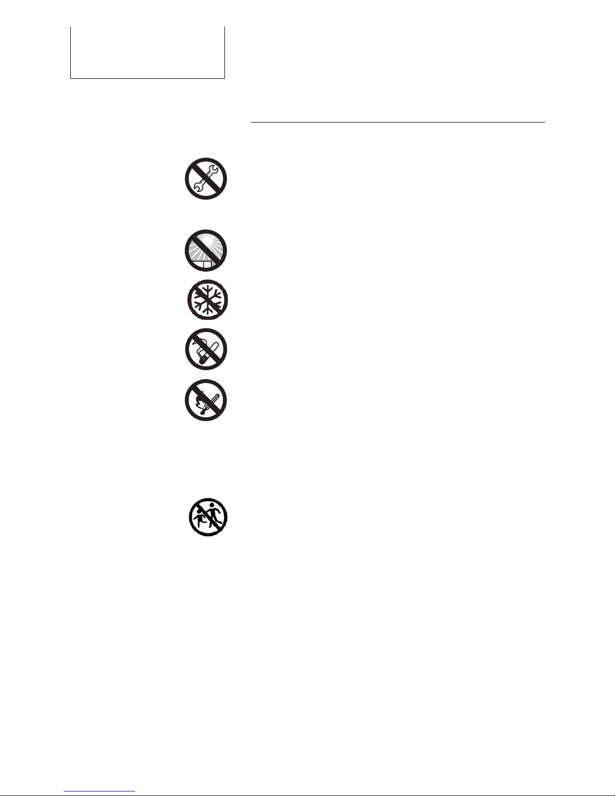
Do not open unit or fuel cartridges. Do not use force to
open cartridges and do not refill them. Any modifications
to the unit may affect safe operation, will lead to a loss of
license and will void the guarantee. Use only original
EFOY equipment.
Do not store unit and fuel cartridges at temperatures
above 45° C. Do not operate at temperatures above 40°
C. Keep away from heat and direct sunlight.
Store the unit where there is no danger of freezing, or
use the automatic antifreeze feature.
Do not smoke when handling the unit or the fuel
cartridges.
Keep away from heat and open flame.
There is a danger of fire if methanol leaks out following
an accident, or if the unit or the fuel cartridge has been
damaged. Keep away from open fire and make sure area
is well ventilated. Small amounts of methanol which may
leak out will evaporate without leaving any residue.
Keep unit and fuel cartridges (including empty or
partially filled cartridges) out of children’s reach.
Operate the unit only in accordance with instructions and
keep operating area well ventilated. Do not block
exhaust. Avoid inhaling exhaust fumes directly or for
prolonged periods of time.

1. Introduction
5
Installation should be carried out by trained personnel
only. Wear proper work clothes. Avoid flowing garments
and wear a hair net if you have long hair. Clothing and hair
can get caught in moving or rotating parts such as in a
drill.
Be sure to leave enough space behind the installation area
when drilling or cutting out openings. Also be sure to
follow the tool manufacturer’s safety instructions.
Solvents used in sealants may emit fumes. Make sure that
there is sufficient ventilation and follow the instructions
for the sealing compound.
Electrical installation work should be done by a licensed
electrician only.
All electrical lines must be adequately insulated and
protected with proper fuses.
Bare wires and contacts are not permitted.
Use the wire harness (included) to connect the unit.
Check the polarity (see illustration) before connecting the
unit.
Both sensor and power lines must always be connected.
Always use separate lines for charging and for voltage
metering to the battery. Otherwise, the flow of current will
cause false readings.
1. Introduction
6
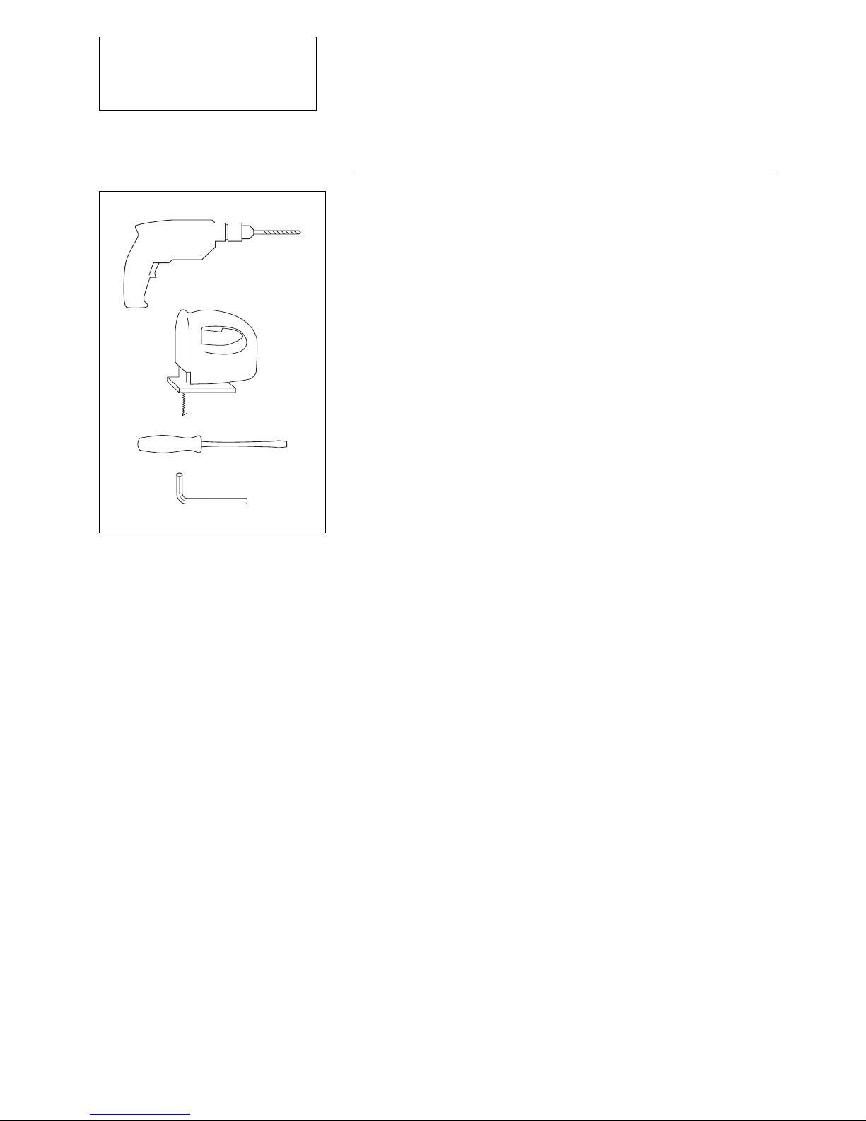
1.2
Tools and Materials
You will need the following tools and sealants to install the
fuel cell in an RV:
electric drill
jigsaw
screwdriver
hexagonal (Allen) wrench
sealant such as Sikaflex
Use the following screws, depending on the mounting
surface (screws are not included):
8 screws to attach the mounting plate
4 screws to attach the remote control
4 screws to attach the fuel-cartridge holder
cable clamps and fixing screws, if needed
Other manuals for 1600
1
This manual suits for next models
2
Table of contents
Other EFOY Inverter manuals

Popular Inverter manuals by other brands


BARRON
BARRON EXITRONIX Tucson Micro Series installation instructions

Baumer
Baumer HUBNER TDP 0,2 Series Mounting and operating instructions

electroil
electroil ITTPD11W-RS-BC Operation and Maintenance Handbook

Silicon Solar
Silicon Solar TPS555-1230 instruction manual

Mission Critical
Mission Critical Xantrex Freedom SW-RVC owner's guide

HP
HP 3312A Operating and service manual


