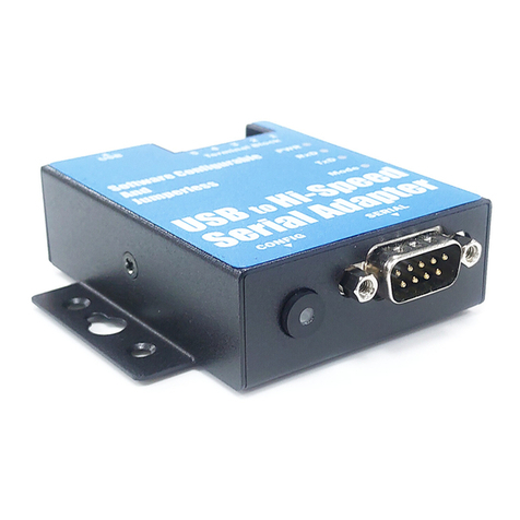
Titan Electronics USB-2CAN-M User manual

1
The computer programs provided with the hardware are supplied under a license. The
software provided should be used only with the NCOM series hardware designed and
manufactured by TITAN Electronics Inc.
Trademarks
TITAN and the logo is a registered trademark of TITAN Electronics Inc. in Taiwan.
Microsoft, Windows, Windows XP, Windows Vista, Windows Server, Windows 7,
Windows 8, Windows 10 are trademarks of Microsoft Corporation. All other
trademarks and brands are property of their respective owners.
Copyright
Copyright © TITAN Electronics Inc. 2016. All right reserved. Reproduction of the
manual and software without permission is prohibited.
Disclaimer
TITAN Electronics Inc. provides this document and computer programs “as is” without
warranty of any kind, either expressed or implied, including, but not limited to, its
particular purpose. TITAN Electronics Inc. reserves the right to make improvements
and changes to this user manual, or to the products, or the computer programs
described in this manual, at any time.
Information provided in this manual is intended to be accurate and reliable. However,
TITAN Electronics Inc. assumes no responsibility for its use, or for any infringements
on the rights of third parties that may result from its use.
This product might include unintentional technical or typographical errors. Changes
are periodically made to the information herein to correct such errors, and these
changes are incorporated into new editions of the publication.

2
Contents
1 INTRODUCTION...........................................................................................................5
2 FEATURES....................................................................................................................6
3 DIAGRAM OF USB-2CAN-M/USB-2CAN-SI-M .............................................................7
3.1 BLOCK DIAGRAM..................................................................................................7
3.1.1 USB-2CAN-M Block Diagram.........................................................................7
3.1.2 USB-2CAN-SI-M Block Diagram.....................................................................7
4 SPECIFICATIONS ..........................................................................................................8
5 PIN-OUT INFORMATION ...........................................................................................11
5.1 CAN Bus Pin-out for DB9 connector ..................................................................11
5.2 Enabling the +5V 100mA power for external devices .......................................11
5.3 Termination Resistors ........................................................................................12
6 HARDWARE INSTALLATION.......................................................................................13
7 DRIVER AND SOFTWARE INSTALLATION...................................................................14
7.1 Driver Installation...............................................................................................14
7.2 Verifying the Installation....................................................................................14
7.3 Changing COM Port Properties & COM Port Number.......................................15
7.4 Linux Driver Installation(SocketCAN).................................................................16
7.4.1 Using SocketCAN with USB-CAN.................................................................16
8 FUNCTION DESCRIPTION...........................................................................................17
8.1 LED Indicators ....................................................................................................17
8.2 ASCII Command Set............................................................................................18
8.3 Command list .....................................................................................................19
8.3.1 Opening the CAN Bus Channel....................................................................20
8.3.2 Closing the CAN Bus Channel......................................................................20
8.3.3 Setting CAN Bitrate (Standard) ...................................................................21
8.3.4 Setting CAN Bitrate (Advanced)..................................................................22
8.3.5 Transmitting a Standard CAN Frame ..........................................................23
8.3.6 Transmitting a Standard Remote Request CAN Frame ..............................23
8.3.7 Transmitting an Extended CAN Frame........................................................24
8.3.8 Transmitting an Extended Remote Request CAN Frame............................24
8.3.9 Setting Timestamps ON/OFF ......................................................................25
8.3.10 Setting Acceptance Mask..........................................................................26
8.3.11 Setting Acceptance Code ..........................................................................27
8.3.12 Getting Status Flags ..................................................................................28

3
8.3.13 Getting Version Information.....................................................................30
8.3.14 Getting Serial Number ..............................................................................30
8.3.15 Resetting the USB CAN adapter................................................................30
9 TOOLS........................................................................................................................31
9.1 Setting 3MBit Baud Rate for Better CAN Bus Performance ..............................31
9.2 Firmware Upgrade .............................................................................................32
9.3 CANHacker .........................................................................................................33
9.3.1 Settings procedure for selecting and configuring the USB to CAN adapter
..............................................................................................................................34
9.3.2 Receiving CAN frames.................................................................................36
9.3.3 Sending CAN frames ...................................................................................36
9.3.4 Assistant features .......................................................................................38
9.4 Titan CAN Test Program.....................................................................................40
9.4.1 Settings procedure for selecting and configuring the USB to CAN adapter
..............................................................................................................................41
9.4.2 Receiving CAN frames.................................................................................43
9.4.3 Sending CAN frames ...................................................................................43
9.4.4 Assistant features .......................................................................................45
9.5 CANopen ............................................................................................................49
9.5.1 How to get CanFestival ...............................................................................49
9.5.2 Linux Compilation and installation .............................................................49
9.5.4 Windows Compilation.................................................................................50
9.5.5 Compilation with Visual Studio...................................................................50
9.6 APPLICATION PROGRAMMING INTERFACE .......................................................53
9.6.1 CAN_Open...................................................................................................54
9.6.2 CAN_Close...................................................................................................56
9.6.3 CAN_Write ..................................................................................................57
9.6.4 CAN_Read ...................................................................................................58
9.6.5 CAN_Flush...................................................................................................59
9.6.6 CAN_Status .................................................................................................60
9.6.7 CAN_Version ...............................................................................................62
9.6.8 CAN_MSG Structure....................................................................................63
9.6.9 Example Code for C.....................................................................................64
9.6.10 Using the API in C#....................................................................................66
9.6.11 Using the API in Visual Basic .NET.............................................................67
9.6.12 Using the API in Visual Basic 6.0 ...............................................................69

5
1INTRODUCTION
A Controller Area Network (CAN) is a high-integrity asynchronous serial bus system for
networking intelligent devices. It is often used in automotive and industrial systems.
The USB-2CAN-M/USB-2CAN-SI-M are designed to make a fast, simple way to
communicate with CAN bus devices. Connected to a USB port on your computer or
USB hub, the USB-2CAN-M/USB-2CAN-SI-M instantly adds an industrial CAN bus
channel to your host system with easy plug and play (PnP) and hot plug features.
The USB-2CAN-M/USB-2CAN-SI-M provides a cost-effective solution for customers to
enable communication with CAN bus devices. The solution designed by ARM Cortex-
M0 32-bit microcontroller and the USB to serial chip makes it very flexible in handling
small burst of CAN frames at a high speed.
Upon plugging the USB-2CAN-M/USB-2CAN-SI-M into the USB port, the adapter is
automatically detected and installed. The USB CAN bus adapter provides instant
connectivity to CAN bus devices. The USB-2CAN-M/USB-2CAN-SI-M provides an
industrial solution for applications of CAN bus multi-drop communications over short
and long distances.
The USB to CAN adapter does not require a power supply. It is powered by a USB port.
The USB-2CAN-M requires 300mA, while the USB-2CAN-SI-M requires 500mA. They
must be connected directly to a USB host port or a self-powered USB hub. However,
bus-powered USB hubs cannot provide the required current, as they only provide
100mA current.
The USB-2CAN-SI-M has 2500V galvanic isolation on its CAN bus. The galvanic isolation
protects your computer by preventing spikes and surges from crossing over to your
computer.

6
2FEATURES
•Adds two CAN bus port on your computer by connecting to USB 1.1, 2.0 or 3.0 host
and hub ports
•Two DB9 male connector
•Includes one USB A/B cable. Cable length: 90cm
•Provides DC +5V 100mA power for external devices
•Powered by USB port, no external power adapter required
•LEDs indicate initialization and CAN bus status
•Installs as standard Windows COM port; COM port number can be changed to any
COM port number
•CAN bus speed up to 1Mbits
•512 bytes receive FIFO and 512 bytes transmit FIFO buffer for high speed data
throughput
•Supports CAN 2.0A and CAN 2.0B protocols
•Supported CAN modes
oStandard mode: normal operation on CAN bus
oListen mode: passive receiving of CAN frames
oEcho mode: transmitter also receives sent frames (for testing purposes)
•Easy plug and play installation and CAN bus device connection
•USB CAN adapter can be controlled over serial port using simple ASCII commands
•USB-2CAN-SI-M has a 2500V galvanic isolation on its CAN bus
•Wide ambient temperature operation 0°C to 60°C (32°F to 140°F)
•CE, FCC approval
•Designed by ARM Cortex-M0 32-bit microcontroller and the USB to UART chip
•Drivers provided for Windows and Linux OS

7
3DIAGRAM OF USB-2CAN-M/USB-2CAN-SI-M
3.1 BLOCK DIAGRAM
3.1.1 USB-2CAN-M Block Diagram
3.1.2 USB-2CAN-SI-M Block Diagram

8
4SPECIFICATIONS
The tables below show the specifications of USB to 2-port CAN bus adapter:
General
USB Bus
USB 2.0 Full Speed, USB 1.1 compliant
CAN Bus
Supports CAN 2.0A and CAN 2.0B
Chipset
ARM Cortex-M0 32-bit microcontroller
Plug & Play
Supported
IRQ &IO Address
Assigned by system
USB-2CAN-M
Number of Ports
Two
Connector DB9 male connector
5-pin terminal block
CAN Bus Speed
5kbits to 1Mbits for CAN data transmit & receive
Signals
CAN_H, CAN_L, CAN_GND, CAN_V+
CAN Bus Controller
Bosch C_CAN module
LED
CAN bus data activity, CAN bus error
CAN Bus Mode
Standard mode: normal operation on CAN bus
Listen mode: passive receiving of CAN frames
Echo mode: transmitter also receives sent frames (for testing
purposes)
Protection
+/-16 KV ESD protection for CAN signals

9
USB-2CAN-SI-M
Number of Ports
Two
Connector DB9 male connector
5-pin terminal block
CAN Bus Speed
20kbits to 1Mbits for CAN data transmit & receive
Signals
CAN_H, CAN_L, CAN_GND, CAN_V+
CAN Bus Controller
Bosch C_CAN module
LED
CAN bus data activity, CAN bus error
CAN Bus Mode
Standard mode: normal operation on CAN bus
Listen mode: passive receiving of CAN frames
Echo m
ode: transmitter also receives sent frames (for
testing purposes)
Protection +/-16 KV ESD protection for CAN signals
2500V galvanic isolation on CAN bus
Software Features
API Library
Supports C/C++, C#, VB.NET and LabVIEW
Utility
On-board firmware update utility
OS Driver Support Windows XP to Windows 10 OS
Windows Server 2003 to 2012 R2
Monitoring Tools
Supported by CANHacker, Titan CAN test program
Power Requirement
Power Input Power supplied via USB (5V) connector
No external power needed
Power Consumption Max. 300mA@5VDC (USB-2CAN-M)
Max. 500mA@5VDC (USB-2CAN-SI-M)
Mechanical
Casing
SECC sheet metal (1mm)
Dimensions
115 mm x 85 mm x 28 mm (L x W x H)
Weight
310g

10
Environment
Operating Temperature
0°C to 60°C (32°F to 140°F)
Storage Temperature
-20°C to 75°C (-4°F to 167°F)
Humidity
5% to 95% RH
Safety Approvals
CE, FCC

11
5PIN-OUT INFORMATION
Following are the pin-out of connector for USB to CAN bus adapter:
5.1 CAN Bus Pin-out for DB9 connector
Pin Number
Signals
Description
1
CAN_V+ Provides +DC 5V 100mA power (optional)
2
CAN_L CAN_L bus line (dominant level is low)
3
CAN_GND Signal ground
4
- Reserved
5
- Reserved
6
CAN_GND Signal ground
7
CAN_H CAN_H bus line (dominant level is high)
8
- Reserved
9
CAN_V+ Provides +DC 5V 100mA power (optional)
5.2 Enabling the +5V 100mA power for external devices
Inside the unit, there is a 2-pin header block (JP5,JP8) which are jumpers for enabling
5V 100mA power for external devices.
JP3 Jumper
Function
ON Enable DB9 pins 1 and 9 to provide a 5V 100mA power for external
devices
OFF
Disable the 5V 100mA power

12
5.3 Termination Resistors
The USB CAN adapter does not provide CAN bus termination resistors. A CAN bus
network requires 120Ωtermination resistors at each end. Generally, this must be done
in the cabling. Since this depends on the installation of connections, please check your
CAN bus cable specification for proper impedance matching.

13
6HARDWARE INSTALLATION
The USB CAN adapter is a plug and play device. In most cases, the USB CAN adapter’s
drivers will be installed automatically.
Connect the USB CAN adapter to an unused USB port on your computer.
After the software drivers are loaded, you will find a new "USB Serial Port (COMX)"
under “Ports (COM & LPT)” in device manager.
You will need to execute the command “CAN_BAUDRATE_SET COMX” to set the USB
to CAN adapter to work in high speed (3Mbits). After executing the command,
please disconnect the USB to CAN adapter from the system for about 5 seconds and
connect it again (refer to page 31).
Note: The set baud rate program (CAN_BAUDRATE_SET.exe) must be executed under
command prompt with administrative privileges.

14
7DRIVER AND SOFTWARE INSTALLATION
7.1 Driver Installation
In most cases, the driver of USB CAN adapter will be installed driver automatically.
Windows 10, 8.1, 8, 7, Server 2012 R2, Server 2008 R2
Connect your computer to Internet and plug USB CAN adapter to the USB port. The
driver will be installed automatically via Internet.
Windows XP, Vista, Server 2003 and 2008
Connect your computer to Internet and plug USB CAN adapter to the USB port, when
asked to install the drivers, allow your computer to search the Internet to load and
install the drivers automatically.
7.2 Verifying the Installation
You can verify the installation by looking under device manager (Start →Settings →
Control Panel →System Properties →Hardware →Device Manager).
The device should have installed as a "USB Serial Port (COMX)" under “Ports (COM &
LPT)”.

15
7.3 Changing COM Port Properties & COM Port Number
This feature is particularly useful for programs such as HyperTerminal, which only
work with COM1 through COM4. Please ensure that you do not change to a COM port
number that is already in use.
To change the virtual COM port properties:
1. Select the "USB Serial Port (COMX)".
2. Click “Properties”.
3. Select "Port Setting" and “Advanced”.
4. Click the drop down arrow on COM Port Number and scroll to the required COM
port.
5. Select "OK".
6. Return to the Device Manager Screen. You will see that the USB Serial Port
installation has been changed to the new COM Port Number.

16
7.4 Linux Driver Installation(SocketCAN)
SocketCAN is a set of open source CAN drivers and a networking stack contributed by
Volkswagen Research to the Linux kernel. Formerly known as Low Level CAN
Framework (LLCF).
Installing SocketCAN is rather easy. In fact, it just needs to install can-utils packages.
To proceed , uses the following command:
sudo apt-get install can-utils
By default, the SocketCAN device drivers are not automatically loaded by Linux at boot
time on all systems: you may need to enable the relevant linux kernel modules. You
can manually load these modules with the following command:
sudo modprobe can
sudo modprobe vcan
sudo modprobe slcan
7.4.1 Using SocketCAN with USB-CAN
To use USB-CAN with SocketCAN, you have to establish a “link” between the drivers
and the hardware. This is done with the following command:
sudo slcand -o -c -s8 /dev/ttyUSB0 can0
The -s parameter allow to configure different interface speed as indicated below.
ASCII Command
CAN Bitrate
s0
10 Kbit/s
s1
20 Kbit/s
s2
50 Kbit/s
s3
100 Kbit/s
s4
125 Kbit/s
s5
250 Kbit/s
s6
500 Kbit/s
s7
800 Kbit/s
s8
1000 Kbit/s
If everything worked fine, you should now see the can0 network device. To very it, just
type the following command:
sudo ip link set up slcan0

17
8FUNCTION DESCRIPTION
8.1 LED Indicators
The USB to CAN adapter has two LEDs (green LED & red LED) to indicate firmware
initialization and CAN bus status for monitoring CAN bus channel status. The green
LED indicates CAN bus data activity while the red LED indicates a CAN bus error.
Following are the definition of different LED combinations:
A: Power up (device initialized)
After USB CAN powers up (device initialized), the USB to CAN adapter flashes the
green and red LED four times to indicate that the USB CAN adapter has been initialized.
B: CAN bus channel open/close
When CAN bus channel opens, the green LED will turn on to indicate that the CAN bus
channel is open; When CAN bus channel closes, the green LED will turn off to indicate
that the CAN bus channel is closed.
C: CAN Bus Data Activity
When CAN data frame is sent or received, the green LED flashes continuously to
indicate CAN bus data I/O activity.
D: CAN Bus Error
When an error occurs on the CAN bus, the red LED flashes continuously to indicated
CAN bus error.

18
8.2 ASCII Command Set
The USB CAN adapter can be registered as a virtual serial port on the host computer.
With simple ASCII commands the USB CAN adapter can be controlled over this serial
port. User can send/receive commands from any simple serial terminal program.
Example: Set bitrate to 500Kbps, open CAN channel, send CAN frame (ID = 002h, DLC
= 3, Data = 11 22 33), close CAN:
Command
Response
Function
S6[CR]
[CR]
Set bitrate of USB CAN adapter to 500Kbps
O[CR]
[CR]
Open CAN channel
t0023112233[CR]
z[CR]
Send CAN message (ID = 002h, DLC = 3, Data = 11
22 33)
C[CR]
[CR]
Close CAN channel

19
8.3 Command list
The commands are line based and terminated with newline character CR (0xD). On
error the response will be 0x7 (BELL).
The “help” command (‘H’, ‘h’ or ‘?’) will list supported commands.
Command
Response
Function
H[CR]
[CR]
List all supported commands
h[CR]
[CR]
?[CR]
[CR]
Example: H[CR]
Return Code
List of Supported Commands:
‘O’ – Open the channel in Normal mode
‘L’ – Open the channel in Listen Only mode
‘Y’ – Open the channel in Loopback mode
‘C’ – Close CAN Channel
‘S’ – Set standard CAN bitrate
‘s’ – Set non-standard CAN bitrate
‘t’ – Transmit a standard frame
‘T’ – Transmit an extended frame
‘r’ – Transmit a standard remote request frame
‘R’ – Transmit an extended remote request frame
‘Z’ – Set timestamp on/off
‘m’ – Set acceptance mask
‘M’ – Set acceptance filter
‘F’ – Read status flag
‘V’ – Check software version
‘N’ – Check serial number
‘m’ – Set acceptance mask
‘M’ – Set acceptance filter
‘RST’ – Reset USB CAN Adapter
‘H’, ‘h’ or ‘?’ – List supported commands
This manual suits for next models
1
Table of contents
Other Titan Electronics Adapter manuals


