Titan Electronics USB-COMI PRO User manual

USB-COMI PRO / USB-2COMI PRO USER’S MANUAL
1
The computer programs provided with the hardware are supplied under a license. The
software provided should be used only with the NCOM series hardware designed and
manufactured by TITAN Electronics Inc.
Trademarks
TITAN and the logo are a registered trademark of TITAN Electronics Inc. in Taiwan.
Microsoft, Windows, Windows XP, Windows Vista, Windows Server, Windows 7,
Windows 8, Windows 10 are trademarks of Microsoft Corporation. All other
trademarks and brands are property of their respective owners.
Copyright
Copyright © TITAN Electronics Inc. 2016. All right reserved. Reproduction of the
manual and software without permission is prohibited.
Disclaimer
TITAN Electronics Inc. provides this document and computer programs “as is” without
warranty of any kind, either expressed or implied, including, but not limited to, its
particular purpose. TITAN Electronics Inc. reserves the right to make improvements
and changes to this user manual, or to the products, or the computer programs
described in this manual, at any time.
Information provided in this manual is intended to be accurate and reliable. However,
TITAN Electronics Inc. assumes no responsibility for its use, or for any infringements
on the rights of third parties that may result from its use.
This product might include unintentional technical or typographical errors. Changes
are periodically made to the information herein to correct such errors, and these
changes are incorporated into new editions of the publication.

USB-COMI PRO / USB-2COMI PRO USER’S MANUAL
2
Contents
1 INTRODUCTION ................................................................................................. 4
2 FEATURES .......................................................................................................... 5
2.1 USB-COMi PRO............................................................................................. 5
2.2 USB-2COMi PRO........................................................................................... 5
3 SPECIFICATIONS ................................................................................................. 7
3.1 USB-COMi PRO............................................................................................. 7
3.2 USB-2COMi PRO........................................................................................... 8
4 HARDWARE CONFIGURATION .......................................................................... 10
4.1 Configuration via Windows Software ......................................................... 11
5 SERIAL PORT CONNECTOR PINOUT .................................................................. 14
5.1 RS-232 Mode Pinout of 9-pin D-sub Connector .......................................... 14
5.2 RS-232 Mode Pinout of 5-pin Terminal Block.............................................. 14
5.3 RS-422 Mode Pinout .................................................................................. 15
5.4 RS-485 Full-Duplex Mode Pinout................................................................ 16
5.5 RS-485 Half-Duplex Mode Pinout ............................................................... 17
6 PROPER WIRING FOR RS-422/485 OPERATION................................................. 18
6.1 RS-422 & RS-485 Transmission Technique .................................................. 18
6.2 RS-422 Signals Connected .......................................................................... 18
6.3 RS-422 & RS-485 4-wire Scheme ................................................................ 19
6.4 RS-485 2-wire Scheme ............................................................................... 19
7 INSTALLING WINDOWS DRIVER........................................................................ 20
7.1 Installing in Windows 10, 8.1, 8, 7, Server 2012 and 2008 R2 ..................... 20
7.2 Installing in Windows XP, Vista, Server 2003 and 2008 ............................... 20
8 PRE-INSTALLING WINDOWS DRIVER................................................................. 21
9 UNINSTALLING WINDOWS DRIVER................................................................... 24
9.1 Supported Operating Systems .................................................................... 24
9.2 Running the Application............................................................................. 24
9.3 Removing a Driver...................................................................................... 24
9.4 Error Messages .......................................................................................... 25
10 Share USB Serial Ports to a Network via Internet, LAN, WAN............................ 27
11 RUNNING AnyplaceUSB SOFTWARE TO SHARE SERIAL DEVICES ....................... 31
11.1 Connect your PC to a Network ................................................................. 31
11.2 Connect the AnyplaceUSB-xCOM USB Serial Adapter ............................... 31
11.3 Running AnyplaceUSB Software Program in SERVER mode....................... 32
11.4 Share the USB Serial Port to Network....................................................... 34
11.5 Share the USB Serial Device Automatically ............................................... 35

USB-COMI PRO / USB-2COMI PRO USER’S MANUAL
3
11.6 Share the USB Serial Device with Manual Options.................................... 37
11.7 Get Status for Shared USB Serial Device ................................................... 41
11.8 Un-share the USB Serial Devices............................................................... 42
11.9 Refreshing the Information of Shared USB Serial Devices ......................... 42
11.10 “Minimize” Button ................................................................................. 42
12 CONNECT TO REMOTE USB SERIAL DEVICES..................................................... 44
12.1 Install AnyplaceUSB Software Program in Client Computer ...................... 44
12.2 Running AnyplaceUSB Software Program in Client Computer................... 48
12.3 Running AnyplaceUSB Software Program in CLIENT Mode ....................... 49
12.4 Connect Remote Shared Serial Device to your Computer ......................... 51
12.5 Disconnect Shared USB Serial Device from your Computer ...................... 53
12.6 Other Buttons in CLIENT Mode................................................................. 54
12.6.1 “Add Server” Button......................................................................... 54
12.6.2 “Add Device” Button ........................................................................ 55
12.6.3 “Remove” Button ............................................................................. 59
12.6.4 “Status” Button ................................................................................ 59
12.6.5 “Refresh” control button.................................................................. 60
12.6.6 “Minimize” control button ............................................................... 60
13 HOW TO SHARE SERIAL DEVICES VIA INTERNET ............................................... 62
13.1 Share the AnyplaceUSB Serial Devices on Local Network First .................. 62
13.2 Checking the IP address for Server Computer........................................... 62
13.3 Port Forwarding to Shared Serial device ................................................... 63
14 AnyplaceUSB SOFTWARE UNINSTALLATION ..................................................... 65
14.1 Uninstalling AnyplaceUSB Software Program ........................................... 65

USB-COMI PRO / USB-2COMI PRO USER’S MANUAL
4
1INTRODUCTION
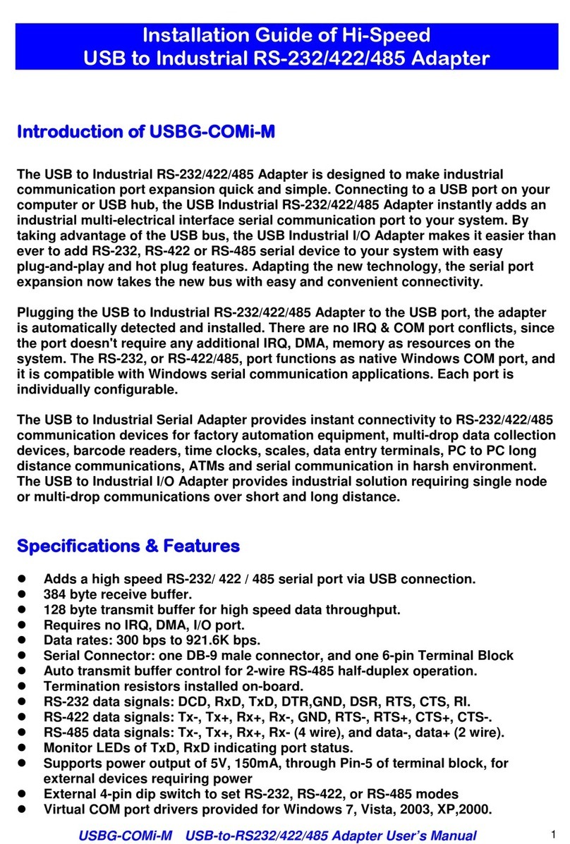
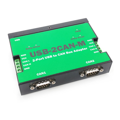
The USB-COMi PRO /USB-2COMi PRO is completely jumperless and free of DIP
switches, all configuration is done by software. Just press the button and use the
configuration program.
Serial ports on USB allow further use of existing devices, even when the computer
doesn’t offer serial ports. Now the USB-COMi PRO /USB-2COMi PRO is extremely
flexible in offered communication standards. Besides the classical RS232 and RS422 it
offers three variants of the RS485 operation. The often-required Termination and
Polarization (BIAS) is also provided by built-in hardware, and it is controlled by the
same configuration software. The driver allows to configure the serial ports for bitrates
of up to 3Mbit/s. In RS232 mode the bitrate is limited to 1 Mbit/s.
Plugging the USB-COMi PRO /USB-2COMi PRO to USB port, the adapter is
automatically detected and installed. There are no IRQ & COM port conflicts, since the
port does not require any additional IRQ, DMA, memory as resources on the system.
The RS-232/422/485 port functions as native Windows COM port, and it is compatible
with Windows serial communication applications.
The USB Industrial I/O Adapter provides instant connectivity to RS-232/422/485
communication device for factory automation equipment, multi-drop data collection
devices, barcode readers, time clocks, scales, data entry terminals, PC to PC long
distance communications and serial communication in harsh environments. The USB
Industrial I/O provides industrial solution for applications requiring single node or
multi-drop communications over short and long distance.
USB-COMi PRO /USB-2COMi PRO is an innovative USB to serial converter providing the
capability of serial devices networking and sharing across any network including
Ethernet, WAN, VLAN, VPN and the Internet. The serial devices connected to the
adapter can be conveniently shared and accessed over Ethernet by multiple remote
client computers.

USB-COMI PRO / USB-2COMI PRO USER’S MANUAL
5
2FEATURES
2.1 USB-COMi PRO
Adds a high-speed RS-232/422/485 serial port via USB connection
Serial operation mode and resistors can be easily changed by software
128 bytes receive and 384 bytes transmit buffer for high speed data throughput
Requires no IRQ, DMA, I/O port
RS-232 max bitrates up to 1Mbps
RS-422/485 max bitrates up to 12Mbps
Connector: one DB9 male connector one 5-pin terminal block connector
Auto transmit buffer control for 2-wire RS-485 half-duplex operation
Termination resistors installed on-board
RS-232 data signals: DCD, RxD, TxD, DTR, GND, DSR, RTS, CTS, RI
RS-422 data signals: Tx-, Tx+, Rx+, Rx-, GND, RTS-, RTS+, CTS+, CTS-
RS-485 data signals: Tx-, Tx+, Rx+, Rx- (4-wire), and data-, data+ (2-wire)
Monitor LEDs of TxD, RxD, Mode indicating port status
Easy operating mode configuration and setting
Virtual COM port drivers provided for Windows 10, 8.1, 8, 7, Vista, 2012, 2008,
2003, XP
Any serial device connected to USB-COMi PRO can be accessed and used by
any client computers over network or across the Internet
Shares serial port between multiple computers from anyplace in the world
via Ethernet/WAN/VLAN/VPN/Internet
2.2 USB-2COMi PRO
Adds two high-speed RS-232/422/485 serial port via USB connection
Serial operation mode and resistors can be easily changed by software
128 bytes receive and 384 bytes transmit buffer for high speed data throughput
Requires no IRQ, DMA, I/O port
RS-232 max bitrates up to 1Mbps
RS-422/485 max bitrates up to 12Mbps
Connector: two DB9 male connector two 5-pin terminal block connector
Auto transmit buffer control for 2-wire RS-485 half-duplex operation
Termination resistors installed on-board
RS-232 data signals: DCD, RxD, TxD, DTR, GND, DSR, RTS, CTS, RI
RS-422 data signals: Tx-, Tx+, Rx+, Rx-, GND, RTS-, RTS+, CTS+, CTS-
RS-485 data signals: Tx-, Tx+, Rx+, Rx- (4-wire), and data-, data+ (2-wire)

USB-COMI PRO / USB-2COMI PRO USER’S MANUAL
6
Monitor LEDs of TxD, RxD, Mode indicating port status
Easy operating mode configuration and setting
Virtual COM port drivers provided for Windows 10, 8.1, 8, 7, Vista, 2012,
2008, 2003, XP
Any serial device connected to USB-2COMi PRO can be accessed and used by
any client computers over network or across the Internet
Shares serial port between multiple computers from anyplace in the world
via Ethernet/WAN/VLAN/VPN/Internet

USB-COMI PRO / USB-2COMI PRO USER’S MANUAL
7
3SPECIFICATIONS
3.1 USB-COMi PRO
USB Bus
Compliance USB 2.0 full Speed, USB 1.1 compliant
Speed 12Mbps, full-speed USB
Connector USB type B
FIFO 128 bytes transmit and 384 bytes receive
Operating Systems
Windows 2000 up to Windows 10
Windows Server 2000 up to 2018
Linux kernel 2.6+
Mac OS X support available
Installation The driver is already installed (Linux), or automatically
downloading and installing device drivers after Device
connection (Windows).
Serial Interface
Interface RS-232/422/485 configured by software
RS485 Termination and Polarization configured by
software
Number of Ports 1
Connector DB9 male and 5-pin terminal block
LEDs TxD/RxD/Mode for each port
Max. Speed RS-232:up to 1Mbps RS-422/485:up to 3Mbps
RS-232 Signals DCD, RxD, TxD, DTR, GND, DSR, RTS, CTS, RI
RS-422 Signals TxD-, TxD+, RxD+, RxD-, GND, RTS-, RTS+, CTS+, CTS-
RS-485 Signals (4 wire) TxD-, TxD+, RxD+, RxD-, GND
RS-485 Signals (2 wire) Data-, Data+, GND
Protection
15kV ESD protection for all signals
Serial Communication Parameters
Data Bits
7, 8
Parity None, Even, Odd, Mark, Space
Stop Bit
1, 2
Flow Control Hardware (RTS, CTS), XON/XOFF
Power
Power Input Power supplied via USB connector
No external power needed

USB-COMI PRO / USB-2COMI PRO USER’S MANUAL
8
Mechanical
Dimensions
57 x 72 x 22 mm (W×L×H)
82 x 77 x 22 mm with DB9 connector and ears
Casing SECC metal chassis with DIN rail bracket
Environmental
Operating Temperature 0°C to 55°C (32°F to 131°F)
Storage Temperature -20°C to 75°C (-4°F to 167°F)
Operating Humidity 5% to 95% RH
Safety Approvals CE, FCC
3.2 USB-2COMi PRO
USB Bus
Compliance USB 2.0 full Speed, USB 1.1 compliant
Speed
12Mbps, full-speed USB
Connector USB type B
FIFO
128 bytes transmit and 384 bytes receive
Operating Systems Windows 2000 up to Windows 10
Windows Server 2000 up to 2018
Linux kernel 2.6+
Mac OS X support available
Installation The driver is already installed (Linux), or automatically
downloading and installing device drivers after Device
connection (Windows).
Serial Interface
Interface RS-232/422/485 configured by software
RS485 Termination and Polarization configured by
software
Number of Ports 2
Connector DB9 male and 5-pin terminal block
LEDs TxD/RxD/Mode for each port
Max. Speed RS-232:up to 1Mbps RS-422/485:up to 3Mbps
RS-232 Signals DCD, RxD, TxD, DTR, GND, DSR, RTS, CTS, RI
RS-422 Signals
TxD-, TxD+, RxD+, RxD-, GND, RTS-, RTS+, CTS+, CTS-
RS-485 Signals (4 wire) TxD-, TxD+, RxD+, RxD-, GND
RS-485 Signals (2 wire)
Data-, Data+, GND
Protection 15kV ESD protection for all signals
Serial Communication Parameters

USB-COMI PRO / USB-2COMI PRO USER’S MANUAL
9
Data Bits 7, 8
Parity
None, Even, Odd, Mark, Space
Stop Bit 1, 2
Flow Control
Hardware (RTS, CTS), XON/XOFF
Power
Power Input Power supplied via USB connector
No external power needed
Mechanical
Dimensions 115 x 85 x 26 mm (W×L×H)
137 x 90 x 23 mm with DB9 connector and ears
Casing SECC metal chassis with DIN rail bracket
Environmental
Operating Temperature 0°C to 55°C (32°F to 131°F)
Storage Temperature
-20°C to 75°C (-4°F to 167°F)
Operating Humidity 5% to 95% RH
Safety Approvals
CE, FCC

USB-COMI PRO / USB-2COMI PRO USER’S MANUAL
10
4HARDWARE CONFIGURATION
CONFIG button with blue LED
CONFIG button with blue LED
PWR LED
RxD LED
TxD LED
Mode LED
5-pin terminal block
USB type B Connector
DB9 Connector
5-pin terminal block
DB9 Connector
PWR LED
RxD LED
TxD LED
Mode LED
USB type B Connector

USB-COMI PRO / USB-2COMI PRO USER’S MANUAL
11
4.1 Configuration via Windows Software
Close any application currently operating via the serial port(s) provided by your USB-
COMi PRO/USB-2COMi PRO. Press the CONFIG button until the CONFIG LED light. Then
start the USB-COM_CFG program, it searches and detects all configurable USB-COMi
PRO/USB-2COMi PRO.

USB-COMI PRO / USB-2COMI PRO USER’S MANUAL
12
The left panel displays all devices detected by the search.
By clicking a port in the left panel, the operation mode is then changed by the radio
buttons and the check box in the right panel. The button to “Commit Changes”
transfers the required parameters to the selected device. They are stored in
nonvolatile RAM and activated after the transfer.

USB-COMI PRO / USB-2COMI PRO USER’S MANUAL
13
You may select several ports of one device at the same time. This is done by the usual
Windows method, i.e. clicking with Shift- or Ctrl-Key pressed. The selected
configuration then applies to all selected ports, “Commit Changes” configures all of
them at the same time. Finally, in the left panel you may select multiple devices at the
same time. The configuration then applies to all ports of all selected devices.

USB-COMI PRO / USB-2COMI PRO USER’S MANUAL
14
5SERIAL PORT CONNECTOR PINOUT
5.1 RS-232 Mode Pinout of 9-pin D-sub Connector
The RS-232 serial ports are configured as data terminal equipment (DTE), with a 9-pin
D-sub connector. Pin assignments are according to TIA/EIA-574, which formally defines
the assignments for a COM port that are found on many personal computers.
Pin Number
Pin Type
Description
1
Input DCD Data Carrier Detect
2
Input RxD Receive Data
3
Output TxD Transmit Data
4 Output DTR Data Terminal Ready
5
Ground
GND
Signal Ground
6 Input DSR Data Set Ready
7
Output
RTS
Request to Send
8 Input CTS Clear to Send
9
Input RI Ring Indicator
RS-232 pinout for DB-9 connector
5.2 RS-232 Mode Pinout of 5-pin Terminal Block
Pin Number
Pin Type
Description
1
Input DCD Data Carrier Detect
2
Input RxD Receive Data
3
Output TxD Transmit Data
4
Output DTR Data Terminal Ready
5 Ground GND Signal Ground
RS-232 pinout for 5-pin terminal block connector

USB-COMI PRO / USB-2COMI PRO USER’S MANUAL
15
5.3 RS-422 Mode Pinout
Pin Number
Pin Type
Description
1
Output
TxD-
Transmit Data, negative polarity
2 Output TxD+ Transmit Data, positive polarity
3
Input
RxD+
Receive Data, positive polarity
4 Input RxD- Receive Data, negative polarity
5
Ground GND
Signal Ground
6
Output RTS- Request to Send, negative polarity
7
Output RTS+ Request to Send, positive polarity
8
Input CTS+ Clear to Send, positive polarity
9
Input CTS- Clear to Send, negative polarity
RS-422 pinout for DB-9 connector
Pin Number
Pin Type
Description
1 Output TxD- Transmit Data, negative polarity
2
Output
TxD+
Transmit Data, positive polarity
3 Input RxD+ Receive Data, positive polarity
4
Input RxD- Receive Data, negative polarity
5 Ground GND
Signal Ground
RS-422 pinout for 5-pin terminal block connector

USB-COMI PRO / USB-2COMI PRO USER’S MANUAL
16
5.4 RS-485 Full-Duplex Mode Pinout
Pin Number
Pin Type
Description
1
Output
TxD-
Transmit Data, negative polarity
2 Output TxD+ Transmit Data, positive polarity
3
Input
RxD+
Receive Data, positive polarity
4 Input RxD- Receive Data, negative polarity
5
Ground GND
Signal Ground
RS-485 full-duplex pinout for DB-9 connector
Pin Number
Pin Type
Description
1
Output TxD- Transmit Data, negative polarity
2
Output TxD+ Transmit Data, positive polarity
3 Input RxD+ Receive Data, positive polarity
4
Input
RxD-
Receive Data, negative polarity
5 Ground GND
Signal Ground
RS-422 full-duplex pinout for 5-pin terminal block connector

USB-COMI PRO / USB-2COMI PRO USER’S MANUAL
17
5.5 RS-485 Half-Duplex Mode Pinout
Pin Number
Pin Type
Description
1
Output/Input
Data-
Transmit/Receive Data, negative polarity
2 Output/Input Data+ Transmit/Receive Data, positive polarity
5
Ground
GND
Signal Ground
RS-485 half-duplex pinout for DB-9 connector
Pin Number
Pin Type
Description
1
Output/Input TxD- Transmit/Receive Data, negative polarity
2
Output/Input
TxD+ Transmit/Receive Data, positive polarity
5
Ground GND Signal Ground
RS-485 half-duplex pinout for 5-pin terminal block connector

USB-COMI PRO / USB-2COMI PRO USER’S MANUAL
18
6PROPER WIRING FOR RS-422/485 OPERATION
This section will provide proper wiring information about RS-422 and RS-485 data
communication. It is necessary to have the basic knowledge in order to avoid or find
errors in data transmission. Failures in cabling are responsible for most transmission
problems.
6.1 RS-422 & RS-485 Transmission Technique
The RS-422 and RS-485 use the same balanced transmission method. Signals are not
transmitted as voltage on a single wire, like in RS-232. Instead, two wires are used;
when one carries high voltage, the other one carries low voltage. The signal is defined
by the difference in voltage between those two wires. This hardens the transmission
against noise. Usually twisted pair cables are used, which further reduces the
sensitivity for noise.
To make sure the signals meet the common voltage range, the GND of sender and
receiver must be connected somehow. To ensure the signals are in the valid voltage
range and the differential voltage can be correctly sensed by the receiver, the GND
lines of the transmitter and receiver must be connected.
6.2 RS-422 Signals Connected
The following diagram shows how RS-422 signals are connected.
USB-COMi PRO
U
SB-2COMi PRO

USB-COMI PRO / USB-2COMI PRO USER’S MANUAL
19
6.3 RS-422 & RS-485 4-wire Scheme
The RS-422 requires dedicated wire pairs for transmit and receive. The transmit wires
are used to send data to as many as 10 receivers, as stated in the specifications of RS-
422. Since the USB-to-Industrial Single RS-232/422/485 Adapter uses the RS-485’s line
driver technology, up to 32 receivers are possible. The following diagram shows RS-
422 and RS-485 4-wire scheme:
6.4 RS-485 2-wire Scheme
The following diagram shows RS-485 2-wire scheme:
USB-COMi PRO
U
SB-2COMi PRO
USB-COMi PRO
U
SB-2COMi PRO
This manual suits for next models
1
Table of contents
Other Titan Electronics Adapter manuals

