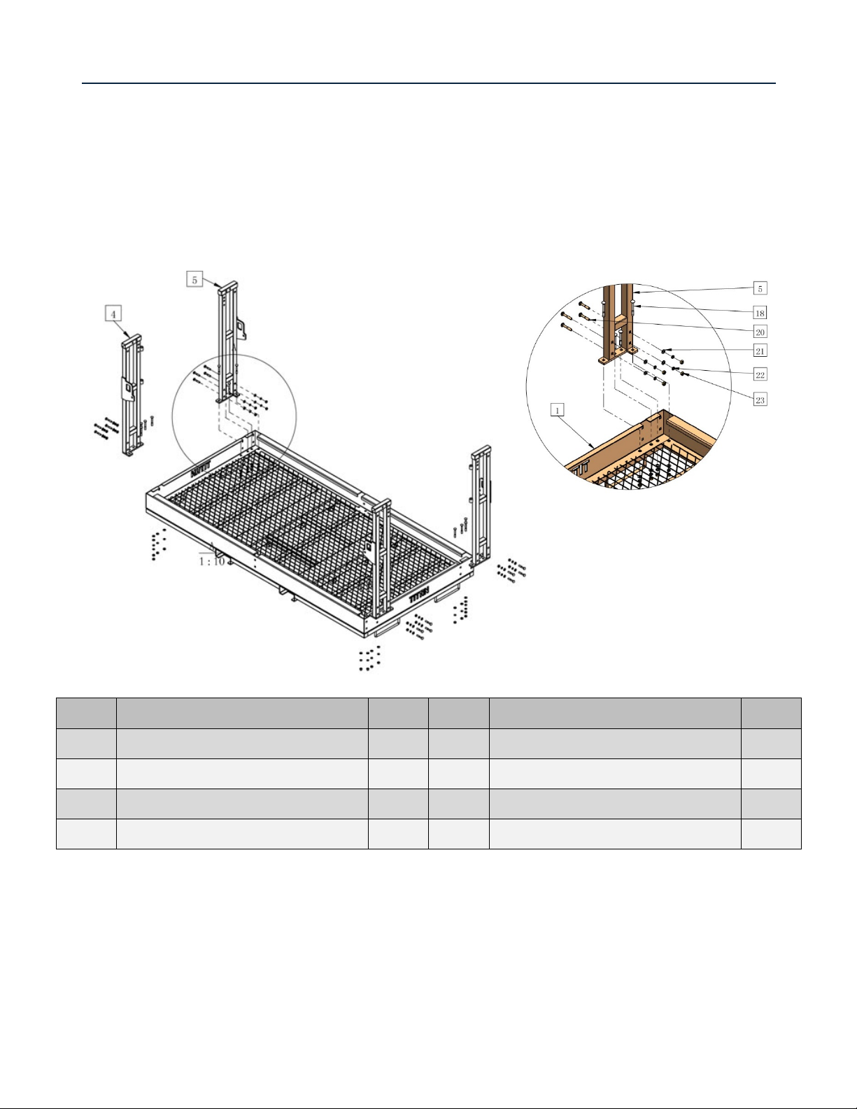
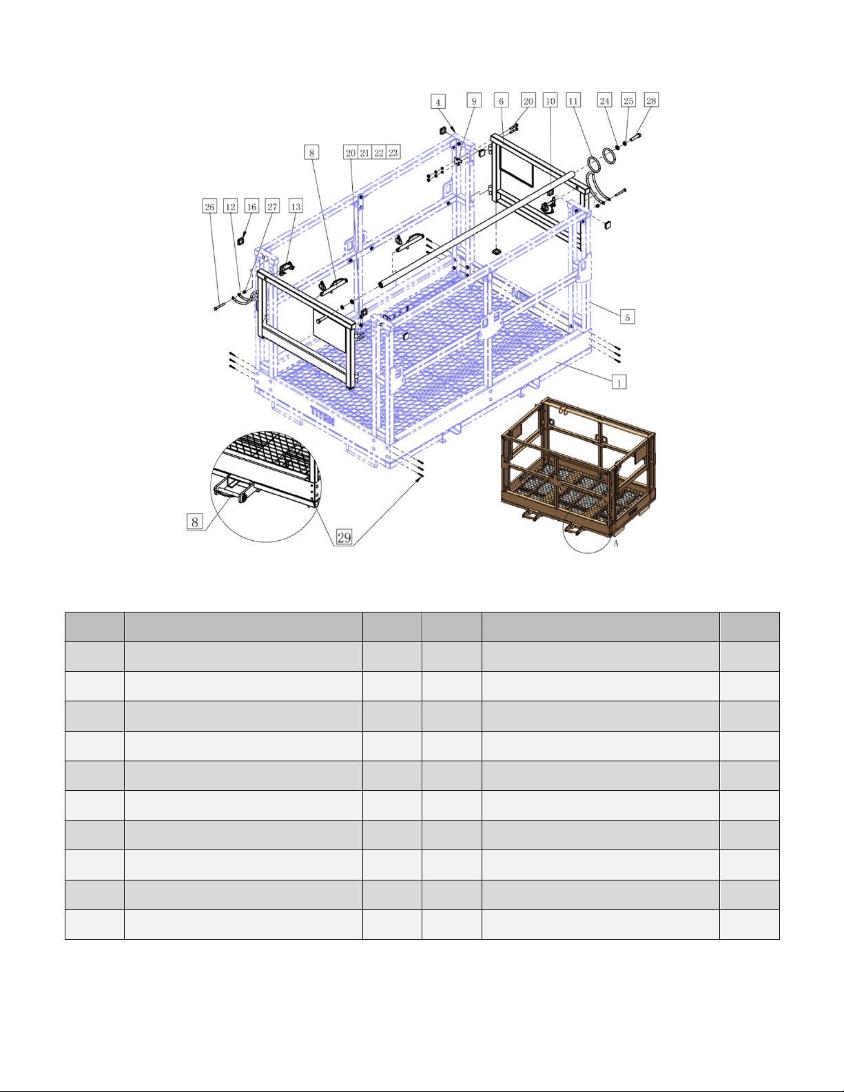
Titan TLEBSK4X6 User manual

TELEHANDLER SAFETY MANBASKET
TLEBSK4X6, TLEBSK4X8, TLEBSK4X98
190502,191503,191504
Operator’s Manual
Read the Operator’s Manual entirely. When you see this
symbol, the subsequent instructions and warnings are
serious follow without exception. Your life and the lives
of others depend on it!

2
INTRODUCTION
THESE ARE STANDARD PRACTICES THAT MAY NOT APPLY TO THE PRODUCTS
DESCRIBED IN THIS MANUAL.
PRECAUTIONS
•This manual is made at the time of manufacturing of the work platform that does not
include any subsequent modifications made afterward.
•This manual is intended to provide information to operators and owners to operate the
work platform safely and effectively, as well as to perform suitable maintenance for the
work platform.
•Before operating or performing maintenance of the work platform, it is critical to read,
understand and be acquainted with the operating, safety, and maintenance
recommendations of this manual, as well as the manual of your forklift or telehandler.
•Failure in operating and maintaining the work platform according to the instructions and
recommendations could lead to fatal accidence causing serious personal injury or death.
SAFETY PRECAUTIONS
THIS SYMBOL BY ITSELF OR WITH A WARNING WORD THROUGHOUT THIS
MANUAL IS USED TO CALL YOUR ATTENTION TO INSTRUCTIONS INVOLVING
YOUR PERSONAL SAFETY OR THE SAFETY OF OTHERS. FAILURE TO FOLLOW
THESE INSTRUCTIONS CAN RESULT IN INJURY OR DEATH.
DANGER
THIS SIGNAL WORD IS USED WHERE SERIOUS INJURY OR DEATH WILL RESULT IF THE
INSTRUCTIONS ARE NOT FOLLOWED PROPERLY.
WARNING
THIS SIGNAL WORD IS USED WHERE SERIOUS INJURY OR DEATH WILL RESULT IF THE
INSTRUCTIONS ARE NOT FOLLOWED PROPERLY.
CAUTION
THIS SIGNAL WORD IS USED WHERE SERIOUS INJURY OR DEATH WILL RESULT IF
THEINSTRUCTIONS ARE NOT FOLLOWED PROPERLY.

3
ASSEMBLY INSTRUCTIONS
SPECIAL NOTES:
•Build on flat and level ground
•Avoid tightening bolts down completely until the rack is fully assembled
•Reference positions: left/right/front/back are from forklift cab viewing the work platform
STEP 1: INSTALLING CORNER FRAMES
KEY DESCRIPTION QTY KEY DESCRIPTION QTY
(1) BASE ASSY 1 (20) CARRIAGE BOLT M10x60 16
(4) CORNER FRAME-1 2 (21) FLAT WASHER M10 32
(5) CORNER FRAME-2 2 (22) SPRING WASHER M10 32
(18) CARRIAGE BOLT M10x80 16 (23) HEX NUT M10 32

4
STEP 1: INSTALLING CORNER FRAMES
1. Rest CORNER FRAME-1 (4) on the left/front corner of the BASE ASSY (1) and align bolt
holes. Insert CARRIAGE BOLT M10x60 (20) through the holes from the side and place FLAT
WASHER M10 (21), SPRING WASHER M10 (22) and HEX NUT M10 (23) onto the end of the
bolt. Then insert CARRIAGE BOLT M10x80 (18) through the bolt holes from the top and
place FLAT WASHER M10 (21), SPRING WASHER M10 (22) and HEX NUT M10 (23) onto the
end of the bolt.
FASTEN BUT DO NOT TIGHTEN HARDWARE.
2. Repeat the above procedures for mounting the second CORNER FRAME-1 (4) on the
right/back diagonal corner of the BASE ASSY (1).
3. Rest CORNER FRAME-1 (5) on the right/front corner of the BASE ASSY (1) and align bolt
holes. Insert CARRIAGE BOLT M10x60 (20) through the holes from the side and place FLAT
WASHER M10 (21), SPRING WASHER M10 (22) and HEX NUT M10 (23) onto the end of the
bolt. Then insert CARRIAGE BOLT M10x80 (18) through the bolt holes from the top and
place FLAT WASHER M10 (21), SPRING WASHER M10 (22) and HEX NUT M10 (23) onto the
end of the bolt. Fasten but do not tighten hardware.
4. Repeat the above procedures for mounting the second CORNER FRAME-1 (5) on the
left/back diagonal corner of the BASE ASSY (1).

5
STEP 2: INSTALLING GUARD RAILS
KEY DESCRIPTION QTY KEY DESCRIPTION QTY
(1) BASE ASSY 1 (17) CARRIAGE BOLT M10x70 4
(2) TOP GUARD RAIL 2 (18) CARRIAGE BOLT M10x80 20
(3) UPRIGHT POST ASSY 2 (19) CARRIAGE BOLT M10x65 10
(4) CORNER FRAME-1 2 (20) CARRIAGE BOLT M10x60 28
(5) CORNER FRAME-2 2 (21) FLAT WASHER M10 62
(7) RAIL MOUNTING PLATE – 1 2 (22) SPRING WASHER M10 62
(14) RAIL MOUNTING PLATE -2 2 (23) HEX NUT M10 62
(15) CENTER GUARD RAIL 4

6
STEP 2: INSTALLING GUARD RAILS
1. Rest UPRIGHT POST ASSY (3) on the middle of the BASE ASSY (1) and align bolt holes. Insert
CARRIAGE BOLT M10x80 (18) through the bolt holes from the top and place FLAT WASHER
M10 (21), SPRING WASHER M10 (22) and HEX NUT M10 (23) onto the end of the bolt. Then
insert CARRIAGE BOLT M10x60 (20) through the holes from the side and place FLAT
WASHER M10 (21), SPRING WASHER M10 (22) and HEX NUT M10 (23) onto the end of the
bolt.
FASTEN BUT DO NOT TIGHTEN HARDWARE.
2. Repeat the above procedures for mounting the second UPRIGHT POST ASSY (3) onto the
BASE ASSY (1).
3. Attach CENTER GUARD RAIL (15) to the center of CORNER FRAME-1 (4) and CORNER
FRAME-2 (5) respectively using CARRIAGE BOLT M10x60 (20), FLAT WASHER M10 (21),
SPRING WASHER M10 (22) and HEX NUT M10 (23). The order of assembly is to push
CARRIAGE BOLT M10x60 (20) through the holes and then place FLAT WASHER M10 (21),
SPRING WASHER M10 (22) and HEX NUT M10 (23) onto the end of the bolt.
FASTEN BUT DO NOT TIGHTEN HARDWARE.
4. Attach CENTER GUARD RAIL (15) to the center of UPRIGHT POST ASSY (3) using RAIL
MOUNTING PLATE – 1 (7), CARRIAGE BOLT M10x70 (17), FLAT WASHER M10 (21), SPRING
WASHER M10 (22) and HEX NUT M10 (23). Repeat the above procedures for mounting the
second CENTER GUARD RAIL (15) on the other face.
5. Attach the 2 ends of TOP GUARD RAIL (2) to using CORNER FRAME-1 (4) and CORNER
FRAME-2 (5) respectively using CARRIAGE BOLT M10x60 (20), FLAT WASHER M10 (21),
SPRING WASHER M10 (22) and HEX NUT M10 (23).
6. Attach the center of TOP GUARD RAIL (2) to the center of UPRIGHT POST ASSY (3) using
RAIL MOUNTING PLATE -2 (14), CARRIAGE BOLT M10x65 (19),FLAT WASHER M10 (21),
SPRING WASHER M10 (22) and HEX NUT M10 (23). Repeat the above procedures for
mounting the second TOP GUARD RAIL (2) on the other face.

7
STEP 3: INSTALLING GATES AND FINAL TOUCH
KEY DESCRIPTION QTY KEY DESCRIPTION QTY
(1) BASE ASSY 1 (20) CARRIAGE BOLT M10x60 4
(4)
CORNER FRAME-1
2
(21)
FLAT WASHER M10
4
(5)
CORNER FRAME-2
2
(22)
SPRING WASHER M10
4
(6) GATE FRAME 2 (23) HEX NUT M10 4
(8)
LOCK PIN ASSY – FORK (8)
2
(24)
FLAT WASHER M16
2
(9) GATE SWING STOPPER 2 (25) SPRING WASHER M16 2
(10)
HARNESS SAFETY BAR
1
(26)
HEX BOLT M10x80
2
(11)
HARNESS LOCK RING
1
(27)
HEX LOCK NUT M10
2
(13) GATE LOCK SAFETY PIN 2 (28) HEX BOLT M16x80 2
(16)
TUBE END PLASTIC CAP
12
(29)
SELF TAPING BOLT
12

8
STEP 3: INSTALLING GATES AND FINAL TOUCH
1. Attach GATE SWING STOPPER (9) onto CORNER FRAME-1 (4) or CORNER FRAME-2 (5)
using CARRIAGE BOLT M10x60 (20), FLAT WASHER M10 (21), SPRING WASHER M10 (22),
and HEX NUT M10 (23). The order of assembly is to push CARRIAGE BOLT M10x60 (20)
through these parts, and then FLAT WASHER M10 (21), SPRING WASHER M10 (22), and
HEX NUT M10 (23) onto the end of the bolt. Fasten hardware but do not tighten. Repeat the
same procedures to mount the STOPPERs onto all 4 CORNER FRAMEs.
2. Plug TUBE END PLASTIC CAP (16) into all open tube ends of CORNER FRAMEs and DOOR
FRAMEs (6).
3. Insert two HARNESS LOCK RING (11) into HARNESS SAFETY BAR (10) and attached the
ends of the HARNESS SAFETY BAR (10) onto the rear DOOR FRAME (6) and CORNER
FRAME-2 (5) using FLAT WASHER M16 (24), SPRING WASHER M16 (25), and HEX BOLT
M16x80 (28). The order of assembly is to insert SPRING WASHER M10 (22) and FLAT
WASHER M10 (21) into HEX BOLT M16x80 (28).
FASTEN HARDWARE BUT DO NOT TIGHTEN.
4. Mount GATE LATCH (12) onto CORNER FRAME-2 (5) at the front and rear faces of the work
platform using HEX BOLT M10x80 (26) and HEX LOCK NUT M10 (27). The order of
assembly is to insert HEX BOLT M10x80 (26) through these parts and fasten with HEX LOCK
NUT M10 (27), but do not tighten.
5. Insert the hinge shaft of GATE FRAME (6) into the shaft sleeve of GATE FRAME (6) . Do this
for both the front and rear faces of the work platform. Close the gates with the gate latch
and lock both gates with GATE LOCK SAFETY PIN (13) on the opposite sides.
6. Insert LOCK PIN ASSY – FORK (8) into the pin brackets at the BASE ASSY (1) bottom fork
channels.
7. Tighten all hardware gradually and adjust make sure that all sides of the work platform is
square and level. Use levelling gauge wherever necessary. When squareness and levelling of
the work platform is assured and all hardware has been tightened, mount three SELF
TAPING BOLT (29) on each of the edges of the front and rear faces as shown in the above
diagram of the BASE ASSY (1) to reinforce the whole structure.

9
OPERATION INSTRUCTIONS
•Work platform operator must acquire appropriate qualification or license to work in
elevated height according to requirements of local regulations.
•Forklift or telehandler operator must acquire appropriate qualification or license and
fully trained to maneuver elevated loads.
•Operator must be mentally sound and not being affected by drugs or alcoholic drinks
during operating the equipment. Alcohol and drugs could reduce alertness and
coordination causing catastrophic accidence with serious personal injury or death. An
operator taking prescription or over the counter drugs should seek medical advice as to
whether he or she can safely operate the equipment.
•Work platform operator must put on OSHA safety lanyard or harness that is locked in
place to the harness ring of the platform.
ENVIRONMENTAL FACTORS
•Avoid working in bad weather including but not limited to heavy rain, snowing, stormy
and windy weather.
•Do not operate in environment that is not well-lite.
•Avoid working on a slope, uneven and slippery ground. Make sure the ground is solid
enough to hold the forklift or telehandler stably and use outrigger if available.
•Beware of overhead power, communication lines and other obstacles to plan safe lifting.
INSPECTIONS BEFORE USE
•Make sure that the forklift or telehandler can be stopped quickly in case of emergency.
•Check structural integrity of platform including, damaged, deformed and wearing of
parts and hardware, cracks in welds, and excessive erosions caused by rusting. Replace
or repair if necessary.
•Check for loosen bolts, nuts and pins and tighten.
•Double check gate latch can be locked securely.
•Double if guard rails are tightly locked onto the work platform.
•Check communication link between forklift operator and personnel on platform is in
good order.
USING THE WORK PLATFORM
•Make sure that the work area is in good working conditions as stated in the previous
ENVIROMENTAL FACTOR section, and all necessary inspections stated in the previous
INSPECTION BEFORE USE section is satisfactorily performed.
•Insert the fork tines fully into the fork channels and secure the fork heel tightly against
the safety pins. Double check if the fork is locked tightly without allowing movements.

10
•Move forklift to designated lifting position and make sure that the forklift or telehandler
is in parking brake (engage outrigger if available) before elevating personnel.
•Platform personnel should enter work platform on ground. After entering platform,
engage the gate latch and safety pin and make sure the gates are locked securely. Put on
safety lanyard or harness and lock it on the harness ring before signaling forklift
operator to elevate.
•When personnel are inside the work platform, elevate or lower the work platform
vertically and level with ground. Perform lifting, lowering and adjustment slowly and
safely.
•Never tilt or turn the work platform when personnel are inside. If tilt or turn functions
are available, the tilt and swing cylinder hydraulics must be disengaged.
•Disengage the lifting/lowering hydraulic when the work platform reached the designated
height.
•Always check if effective communication channel is established in elevated position with
the forklift operator before working on the work platform.
•Never use the forklift or telehandler to transfer or transport personnel in work platform.
•Whenever moving the forklift is necessary, always lower the personnel to ground to exit
the work platform.
•The forklift or telehandler operator must remain all the time in the cab and be alert of
the personnel in the work platform and the surrounding environment.
•Avoid bystanders, pets or livestock entering into the work area.
•Avoid leaning on guard rails freely during working on the work platform.
•Never exceed the load capacity of the work platform as stated in the SPECIFICATIONS
Section below.

11
AFTER USE AND MAINTENANCE
•Only qualified peronnel should make repairs to the work platform. After completing
repair and maintenance, check if the work platform is in good conditions.
•Inspection and maintenance can only be conducted with engine turned off and auxiliary
pressure completely disengaged.
•Lower the work platform to flat ground and let off personnel from the work platform.
•Put on personal protective equipment and apparel.
•Each time after use, clean the work platform thoroughly and remove all debris and dirt.
•Visually inspect if there are any parts damaged or deformed, repair and replace if
necessary.
Check if there is any loosen or damaged hardware, tighten or replace hardware is necessary.
The minimum torque for tightening hardware is shown below:
•M10: 37 lb. Ft (50 N.m)
•M16: 163 lb. Ft (220 N.m)
When the work platform is dry, check places where paint is scratched or worn and repaint if
necessary. Apply antirust oil to surface where necessary.
Store the work platform in shed and dry place.

12
SPECIFICATIONS
Center of gravity to vertical member of fork: 27.56”
TLEBS 4X6
TLEBSK4X8
TLEBSK4X98
OVERALL
DIMENSIONS
(L X W X H)
72”X 54.3” X 46.7” 96”X 54.3” X 46.7” 116”X 54.3” X 46.7”
PRODUCT WEIGHT 485 LB. 542 LB. 628 LB.
LOAD CAPACITY
1700 LB.
FORK CHANNEL
6.25” X 2.5”
HANDRAIL HEIGHT
42”
MATERIAL
STEEL

13
PARTS DIAGRAM / EXPLODED VIEW

14
PARTS DIAGRAM / EXPLODED VIEW
KEY
DESCRIPTION QTY
(1) BASE ASSY 1 (16) TUBE END PLASTIC CAP 8
(2) TOP GUARD RAIL 2 (17)
DOME HEAD CARRIAGE
BOLT M10 70
4
(3) UPRIGHT POST ASSY 2 (18) DOME HEAD CARRIAGE
BOLT M10x80 20
(4) CORNER FRAME-1 2 (19) DOME HEAD CARRIAGE
BOLT M10x65 10
(5) CORNER FRAME-2 2 (20) DOME HEAD CARRIAGE
BOLT M10x60 32
(6) GATE FRAME 2 (21) FLAT WASHER M10 66
(7) RAIL MOUNTING PLATE - 1 2 (22) SPRING WASHER M10 66
(8) LOCK PIN ASSY - FORK 2 (23) HEX NUT M10 66
(9) GATE SWING STOPPER 2 (24) FLAT WASHER M16 2
(10) HARNESS SAFETY BAR 1 (25) SPRING WASHER M16 2
(11) HARNESS LOCK RING 2 (26) HEX BOLT M10x80 2
(12) GATE LATCH 2 (27) HEX LOCK NUT M10 2
(13) GATE LOCK SAFETY PIN 2 (28) HEX BOLT M16x80 2
(14) RAIL MOUNTING PLATE -2 2 (29) SELF TAPING BOLT 12
(15) CENTER GUARD RAIL 4 (30) ALUMINUM COVER PLATE 2

15
ACKNOWLEDGEMENT OF RISK AND RELEASE OF LIABILITY
The use of any equipment, including this one, involves the potential risk of injury. Apart from any
warranty claim that might be presented for a claimed defect in material or workmanship of the product,
you accept and assume full responsibility for any and all injuries, damages (both economic and non-
economic), and losses of any type, which may occur, and you fully and forever release and discharge
Titan, its insurers, employees, officers, directors, associates, and agents from any and all claims,
demands, damages, rights of action, or causes of action, present or future, whether the same be known
or unknown, anticipated, or unanticipated, resulting from or arising out of the use of said equipment.
This equipment must be used with care by capable and competent individuals under supervision, if
necessary.
WARNING
Do not overfill! Mower should be level
when checking oil in gear box.
some activities might be able to cause
electric shock
Sharp objects may be involved.
Use protective cover during maintenance.
TITAN LIMITED WARRANTY: TERMS, EXCLUSIONS AND LIMITATIONS OF REMEDIES
This product comes with a one (1) year limited warranty that can be found at
www.palletforks.com/warranty.html. Please review the same for all details regarding the Titan Limited
Warranty.
THE TITAN LIMITED WARRANTY FOUND AT WWW.PALLETFORKS.COM/WARRANTY.HTML IS
EXCLUSIVE AND IS IN LIEU OF ALL OTHER WARRANTIES, EXPRESS OR IMPLIED, INCLUDING ANY
IMPLIED WARRANTY OF MERCHANTABILITY AND/OR FITNESS FOR A PARTICULAR PURPOSE, EACH
OF WHICH IS HEREBY DISCLAIMED.

16
NEED HELP? CONTACT US FIRST.
1-800-605-7595
info@palletworks.com
www.palletforks.com
© 2021 Titan Brands
This manual suits for next models
5
Table of contents
Other Titan Lawn And Garden Equipment manuals