AGRI EASE BE-TMS Series Application guide

PURCHASE DATE MODEL NO. SERIAL NUMBER
DEALER
HEAVY DUTY
MULCHER
BE-TMSXXXX
OPERATIONS & PARTS MANUAL
FOR MODELS:
• BE-TMS1400
• BE-TMS1550
• BE-TMS1850
• BE-TMS2050
• BE-TMS2300
• BE-TMS2600

TABLE OF CONTENTS
3INTRODUCTION
5TECHNICAL DATA
7SAFETY
13 INSTALLATION
18 USAGE INSTRUCTIONS
22 MAINTENANCE
27 TROUBLESHOOTING
28 EXPLODED VIEW & PARTS LIST

BE-TMSXXXX USER MANUAL 3
INTRODUCTION
Mulcher description
With reference to Fig. 1, the Mulcher is a machine designed and built exclusively for mulching directly on site
(Orchards, vineyards and kiwi plantations) by crushing vegetation; it mulches prunings, grass, straw, tobacco,
artichokes, beets, cotton and pruning residues. It must not be used for other uses or with other materials.
The Mulcher consists of the following parts:
1.5. Mulcher description
With reference to Fig. 1, the Mulcher is a machine designed and built exclusively for mulching directly on site
(Orchards, vineyards and kiwi plantations) by crushing vegetation; it mulches prunings, grass, straw, tobacco,
artichokes, beets, cotton and pruning residues. It must not be used for other uses or with other materials.
The Mulcher consists of the following parts:
1. Power take-o hitch
2. Three point coupling
3. Cardan protective casing
4. Gear box with free wheel
5. Lateral transmission by belt
6. Leveler roller
7. Sliders
8. Hammers
9. Safety protection
10. Pruning collection rods (upon request)
11. Lateral displacement
MULCHER DESCRIPTION BE-TMSxxxx
2
10
1
8
6
9
5
4
11
3
7
Fig. 1
1. Power take-o hitch
2. Three point coupling
3. Cardan protective casing
4. Gear box with free wheel
5. Lateral transmission by belt
6. Leveler roller
7. Sliders
8. Hammers
9. Safety protection
10.Pruning collection rods (upon request)
11. Lateral displacement

4 BE-TMSXXXX USER MANUAL
INTENDED USE
Allowed uses
The Mulcher has been designed and built to mulch prunings, grass, straw, tobacco, artichokes, beets, cotton
and pruning residues of orchards, vineyards and kiwi plantations. When the Mulcher works it guarantees the
required level of safety even in the presence of an insignificant malfunction of its components or hazardous
operating conditions, however, always within the permitted uses.
With reference to the above, the following are considered allowed uses:
• Using the Mulcher to mow crop residue.
The Mulcher must not be used for purposes other than those described in this manual.
Improper uses
The Mulcher, due to its typical construction, may also be suitable for uses other than from those foreseen by
the manufacturer. For this reason, Braber has selected, as non-exhaustive
examples, a series of improper uses that can be reasonably foreseen, which are:
• Using the Mulcher to mow or cut tree branches;
• Using the Mulcher to mulch or cut hedges;
• Using the Mulcher for shredding purposes near frequented areas.
The uses listed above and those not specifically indicated in this manual, including reasonably
foreseeable improper uses, are peremptorily prohibited.
1.6. Intended use
1.6.1. Allowed uses
The Mulcher has been designed and built to mulch prunings, grass, straw, tobacco, artichokes, beets, cotton
and pruning residues of orchards, vineyards and kiwi plantations. When the Mulcher works it guarantees the
required level of safety even in the presence of an insignificant malfunction of its components or hazardous
operating conditions, however, always within the permitted uses.
With reference to the above, the following are considered allowed uses:
-- Using the Mulcher to mow crop residue.
The Mulcher must not be used for purposes other than those described in this manual.
1.6.2. Improper uses
The Mulcher, due to its typical construction, may also be suitable for uses other than from
those foreseen by the manufacturer. For this reason Braber has selected, as non exhaustive
examples, a series of improper uses that can be reasonably foreseen, which are:
-- Using the Mulcher to mow or cut tree branches;
-- Using the Mulcher to mulch or cut hedges;
-- Using the Mulcher for shredding purposes near frequented areas.
The uses listed above and those not specifically indicated in this manual, including reasonably
foreseeable improper uses, are peremptorily prohibited.
INTENDED USE BE-TMSxxxx

BE-TMSXXXX USER MANUAL 5
MODEL WORK (CM) POWER
REQUESTED (HP) N. HAMMERS MASS (KG) DIMENSIONS
(WXLXH CM)
TMS 1400 140 60 - 70 10 700 165x120x115
TMS 1550 155 60 - 80 12 740 180x120x115
TMS 1850 185 60 - 80 14 790 205x120x115
TMS 2050 205 70 - 110 16 870 225x120x115
TMS 2300 230 90 - 110 18 930 250x120x115
TECHNICAL DATA
• Hitch to the tractor: 3-point universal
• No. enter revolutions: 540 rpm (1000 rpm on request)
• Primary transmission: Cardan Shaft
• Secondary transmission: Belts
• Cut height adjustment: Mechanical
• Lateral movement adjustment: Mechanical, hydraulic on request
Model Work
(cm)
Power
requested (HP) N. hammers Mass
(kg)
Dimensions
(W x L x H)
(cm)
TMS 1400 140 60 - 70 10 700 165x120x115
TMS 1550 155 60 - 80 12 740 180x120x115
TMS 1850 185 60 - 80 14 790 205x120x115
TMS 2050 205 70 - 110 16 870 225x120x115
TMS 2300 230 90 - 110 18 930 250x120x115
(540rpm) (1000rpm)
TECHNICAL DATA BE-TMSxxxx
• Hitch to the tractor: 3-point universal
• No. enter revolutions: 540 rpm (1000 rpm on request)
• Primary transmission: Cardan Shaft
• Secondary transmission: Belts
• Cut height adjustment: Mechanical
• Lateral movement adjustment: Mechanical, hydraulic on request
Sound level
The air noise level created by the Mulcher under operating conditions was detected using a sound level
meter with integrator. The measurements were carried out in accordance with ISO 1680-2 at the operator
station with the Mulcher activated empty. Tests performed under the conditions indicated by the standard
produced the following results:
• Tractor with open cab:
Equivalent weighted sound pressure average level: LpAm = 100,1 dB(A).
• Tractor with closed cab:
Equivalent weighted sound pressure average level: LpAm = 97,7 dB(A).
Sound power level: LwA = 114,6 dB(A).
The level of airborne noise emitted by the Mulcher is indicated with reference to the provisions set out
in Directive 2006/42/EC and does not consider the provisions of Directive 2000/14/EC concerning
the environmental noise emission by machinery and equipment intended for outdoor use because the
machine is not included in Annex I - Part A of Legislative Decree no. 262 of 4 September 2002, legislative
implementation of the above-mentioned Directive.

6 BE-TMSXXXX USER MANUAL
EC marking of the Mulcher
Directive 2006/42/EC specifies the minimum conditions with which a machine can be placed on the EU
market. All machines can only be marketed and put into service if the health and safety of persons, domestic
animals or property are not aected. The Mulcher is not an actual machine because it does not have its
own drive system, however, for legal purposes, it is considered interchangeable equipment because once
it is coupled to the agricultural tractor it provides a new function to the assembly and in all respects, it
is equivalent to a machine and must therefore meet the essential health and safety requirements of the
Machinery Directive.
The Mulcher does not fall under one of the machine categories indicated in the list set out in Annex IV of
the Directive (particularly dangerous machinery). In order to certify the conformity of the machine with the
provisions of Directive 2006/42/EC, before placing the product on the market, Braber applied the procedure
described in Art. 5. In this sense, the manufacturer has provided for: compliance with the relevant safety
requirements; availability of the technical file as stipulated in Annex VI; implementation of all the tests
and inspections required by the reference standards and compliance with the essential health and safety
requirements indicated in Annex I of the Directive itself. The construction technical file, which contains the
basic project information and all the characteristics related to machine safety, was drafted in accordance
with the provisions of Annex VI-Part A, and can be made available by the individual indicated in the CE
Declaration of Conformity for any verification carried out by the supervisory authorities, following a justified
request, as provided for by the relevant laws in force. Once Braber has verified that the machine has been
designed and built-in accordance with the provisions of Directive 2006/42/EC and that it can be used safely
in the service conditions specified in this manual, it places the Mulcher on the market and accompanies the
machine with:
• Usage instructions booklet (User manual)
• EC Declaration of conformity
• EC Marking
In designing and manufacturing the Mulcher, Braber has complied with obligations resulting from applying
related European legislative provisions and precisely the following European provisions:
• Directive 2006/42/CE (Machinery safety).
For verification of conformity to European legislative provisions indicated above, the manufacturer applied
the following European standards and technical rules:
• EN 349:1993+A1:2008: MACHINERY SAFETY - Minimum distance to keep from crushing human body parts.
• EN 1037:1995+A1:2008: MACHINERY SAFETY - Preventing unexpected start-up.
• EN ISO 3746:2010: ACOUSTICS - Determining the sound power levels of sources using sound pressure -
Control method on a reflecting surface by measuring an enveloping surface.
• EN ISO 4254-1:2013: AGRICULTURAL MACHINERY - Safety - Part 1: General requirements.
• EN ISO 4254-12:2012: AGRICULTURAL MACHINERY - Safety - Part 12: Disc and drum rotary mulchers and
mulchers.
• EN ISO 11202:2010: ACOUSTICS - Noise emitted by machinery and equipment - Determination of emission
sound pressure levels at a work station and at other specified positions
• Site control method.
• EN ISO 12100:2010: MACHINERY SAFETY - Basic concepts, general principles for design.
• EN ISO 13524:2009: Machines for road maintenance - Safety requirements.
• EN ISO 13849-1:2008: MACHINERY SAFETY - Safety-related parts of control systems - Part 1: General
principles for design.
• EN ISO 13857:2008: MACHINERY SAFETY - Safety distances to prevent hazard zones being reached by
upper and lower limbs.
• EN 15436-1:2008: Equipment for maintenance of green areas along road sides - Part 1: Terminology.
• EN 15436-2:2008: Equipment for maintenance of green areas along road sides - Part 2: Performance
evaluation.
• CEN/TS 15436-3:2009: Equipment for maintenance of green areas along road sides - Part 3: Classification.
• EN 15436-4:2009: Equipment for maintenance of green areas along road sides - Part 4: Acceptance of
delivery of the machines by the user.

BE-TMSXXXX USER MANUAL 7
GENERAL SAFETY AND ACCIDENT PREVENTION STANDARDS
Level of danger
The safety of the operator and exposed persons is the main concern of the designer and the manufacturer
of the machine. When designing a new machine, one tries to plan for all possible danger situations and risks
connected to using the machine, adopting the steps necessary to make the equipment as safe as possible.
The number of accidents remains very high however, especially due to incautious and awkward use of the
machine. It is therefore recommended to carefully read this manual and this section in particular, regarding
safety standards, avoiding behavior that is inappropriate or in contrast with the instructions contained in this
manual.
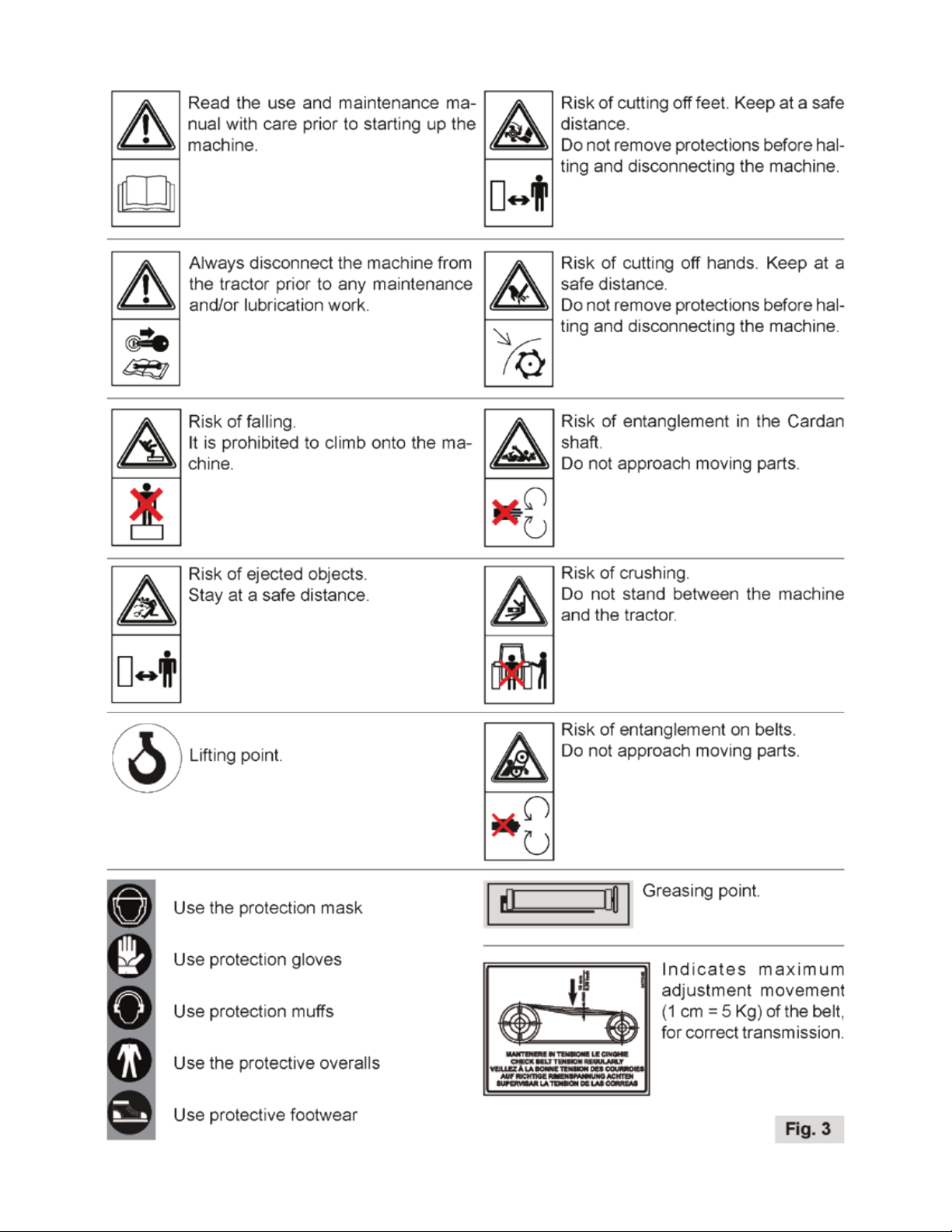
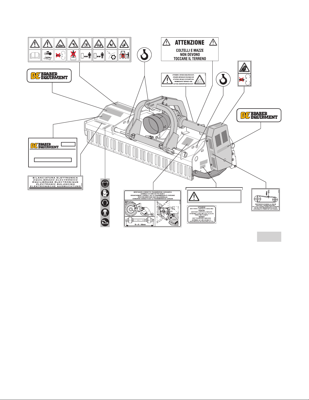
Pay attention to the following danger signal were contained in this manual and follow safety instructions.
DANGER
Indicates a hazardous situation which, if not followed, will result in serious injury or death.
WARNING
Indicates a hazardous situation which, if not avoided, could result in serious injury or death.
CAUTION
Indicates a hazardous situation which, if not followed, could result in minor to moderate injury.
Terminology
The indicated levels of danger refer to specific risk situation that may occur during machine use and may
involve the same machine, the operator and any exposed persons (according to Directive 2006/42/EC).
With the purpose of highlighting situations or operations that may result in risks, the meanings of terms
used in this manual are indicated here:
• HAZARDOUS AREA: Any area in and/or around a machine where the presence of an exposed person
constitutes a risk to the health and safety of said person. (Attachment I, Point 1.1.1., Letter b), Directive
2006/42/EC).
• EXPOSED PERSON: A person fully or partly in a hazardous area (Attachment I, Point 1.1.1., Letter c),
Directive 2006/42/EC).
• OPERATOR: The person or personnel in charge of the installation, the operation, the adjusting, the cleaning,
the repairing and the moving of the machine. (Attachment I, Point 1.1.1., Letter d), Directive 2006/42/EC).
• USER: the person, entity or company, who purchased or rented the machine and intends to use it according
to the intended use foreseen by the manufacturer.
• SPECIALIZED PERSONNEL: any person specifically trained and approved to carry out maintenance or
repair interventions that require particular knowledge of the machine, its operation, the installed safety
devices, intervention modes. It must be capable of recognizing danger present on the actual machine,
therefore avoiding at risk situations.
• RISK: a combination of the probability and seriousness of injury or damage to health which can arise in a
dangerous situation.
• GUARD: a part of the machine that is used to specifically guarantee protection by way of a material barrier.
• PROTECTION DEVICE: a device that reduces risk (unlike the guard) either on its own or together with the
guard.
• INTENDED USE: the use of the machine in accordance with the information provided in the operating
instructions.
• REASONABLY FORESEEABLE MISUSE: the use of the machine dierent to the information provided in the
operator’s instructions, which may be the result of readily predictable human behavior.
• AUTHORIZED ASSISTANCE CENTRE: The Authorized Assistance Centre, legally authorized by the
Manufacturer, is formed by specialized sta able to carry out all types of assistance, maintenance and
repair work, even of a certain complexity, required to maintain the machine in perfect working order.
WARNING
Carefully read the following rules. If the instructions described are not followed, a situation may arise
which causes irreparable damage to the machine or property, or injury - even severe - to people or
animals.

8 BE-TMSXXXX USER MANUAL
Braber declines all responsibility for damage caused by not complying with the safety and injury prevention
regulations described below. Braber also declines any responsibility for damage caused by improper use of
the machine and/or as a result of modifications made without authorization by the manufacturer.
Danger plates and warning
The Mulcher is equipped with pictograms (labels) warning about residual risks present on the machine that it
was not possible to eliminate. Figure 3 specifies the meaning of symbols contained in the pictograms.
The operator must memorize the meaning of the symbols. The labels should always be kept clean and
replaced immediately if they are fully or partially detached or damaged.
Plates with indications and particular warnings for
maintenance and a correct use of some parts of the machine.
The respect of these plates lengthens the duration and the
eciency of the Mulcher.
Check the oil level the first time the machine is used.
Indicates the correct functioning of the Cardan shaft.
Keep clear from the moving machine; Keep at a safe distance.
Do not approach moving parts.

BE-TMSXXXX USER MANUAL 9
DANGER PLATES & WARNINGS CONT. BE-TMSxxxx

10 BE-TMSXXXX USER MANUAL
Figure 4 shows an indication of the precise points on the machine where labels are usually applied by the
manufacturer.
DANGER PLATES & WARNINGS CONT. BE-TMSxxxx
CONTROLLARE OLIO AL PRIMO UTILIZZO DELLA MACCHINA
CONTROLAR EL ACEITE LA PRIMERA VEZ QUE SE UTILIZALA MÁQUINA
CONTRÔLER L’HUILE LORS DE LAPREMIÈRE UTILISATIONDE LA MACHINE
CHECK THE OIL BEFORE USING THE MACHINE FOR THE FIRST TIME
VOR DER ERSTENINBETRIEBNAHME DER MASHINE, DEN ÖLSTAND PRÜFEN.
5470122
Fig. 4
Figure 4 shows an indication of the precise points on the machine where labels are usually applied by
the manufacturer.
2.4. Clothing
In general it is necessary to wear suitable clothing for the work to be carried out. In particular, as far as Mulcher
use, obey the following provisions:
-- It is mandatory to use clothing which is as suitable as possible, meaning not too loose and without any
protruding or moving parts (for example ties or necklaces). Do not wear belts, rings and chains. Always use
sturdy safety footwear. Long hair must be tied using a specific cap.
-- It is mandatory to use protective goggles or a mask before proceeding with the work in order to protect the
face and eyes from vegetable fragments which may be projected outwards during mulching.
-- It is mandatory to use protective mus in order to safeguard hearing from noise from the equipment during
work.
Model No.
Description/ Information
Date Country of Origin
Serial No.
Clothing
In general, it is necessary to wear suitable clothing for the work to be carried out. In particular, as far as
Mulcher use, obey the following provisions:
• It is mandatory to use clothing which is as suitable as possible, meaning not too loose and without any
protruding or moving parts (for example ties or necklaces). Do not wear belts, rings and chains. Always use
sturdy safety footwear. Long hair must be tied using a specific cap.
• It is mandatory to use protective goggles or a mask before proceeding with the work in order to protect
the face and eyes from vegetable fragments which may be projected outwards during mulching.
• It is mandatory to use protective mu s in order to safeguard hearing from noise from the equipment during
work.
Ecology and pollution
Below are the minimum provisions to be followed in order to reduce the risk of environmental impact
connected to the use of the machine according to European directives related to the Eco-compatibility of
products connected to power (Directive 2009/125/EC) and Restrictions in the use of dangerous substances
in electrical and electronic equipment (Directive 2011/65/EU):
• If the Country where the machine is used foresees specific sound emission limits, it is best to adapt to the
provisions in these standards, if necessary, being supplied with suitable protective equipment (earplugs,
mus, etc.).
• It is mandatory to respect current legislation of the Country where the Mulcher is used, related to use

BE-TMSXXXX USER MANUAL 11
and disposal of lubricants and products used for machine cleaning and maintenance, observing the
recommendations of the manufacturer of those products.
• If replacing worn parts or during demolition, one must follow anti-pollution laws foreseen in the country
where the Mulcher is used.
• It is prohibited to pour products used for cleaning or polluting substances into the sewerage drain, on the
ground, in watercourses, or into the environment.
• It is mandatory to collect products used for cleaning and polluting substances in appropriate containers,
store them and deliver them to companies authorized for their disposal.
Demolition and decommissioning
If deciding not to use the Mulcher, it is best to take a few precautions in order to avoid the risk of
environmental pollution. The various parts of the machine must be treated as if they were special waste.
One must proceed by taking apart the equipment, grouping the various parts and components in similar
parts (rubber, metal, plastic, etc.), providing for disposal of these parts separately, according to existing
anti-pollution laws of the Country where the machine was used. Please note that, in general, exhausted
lubricating oil, rubber parts and scrap metals are special waste.
Making idle
If the machine is to be set aside for a long period, it is recommended to:
• Treat the Mulcher according to the instructions contained in the paragraph “5.2. Cleaning the Mulcher”;
• Check the machine and have any damaged parts replaced;
• Fully tighten all screws and bolts, in particular those which secure the cutters;
• Perform a general thorough lubrication;
• Place the Mulcher in a dry area where it cannot be touched by persons not authorized to use it, and rest it
on struts of wood;
• Protect the entire machine with a tarpaulin. If these operations are carried out properly, the user will find
the Mulcher in perfect condition when it is required again.
If the Mulcher is to be dismantled, comply with the relative anti-pollution legislation of the Country of use.
It should not be forgotten that the Manufacturer is always available if you require any assistance or spare
parts.
Safe use
• It is prohibited to use the Mulcher in ways that are dierent from the indications contained in the paragraph
“1.6. Intended use”.
• It is prohibited to use or have the Mulcher used by anyone who has not read and completely understood
the information contained in this manual.
• It is prohibited to use or have the Mulcher used by personnel that are not competent or properly trained or
not in good health or physical condition.
• It is forbidden to drive the agricultural tractor attached to the Mulcher or have it driven by personnel
without an appropriate driving license.
• It is forbidden to approach or stop near the Mulcher when the machine is running.
• It is prohibited to stop between the agricultural tractor and the Mulcher (area taken up by the cardan shaft)
if the combustion engine is running.
• It is forbidden to abandon the driver’s seat on the agricultural tractor with the combustion engine running
when the Mulcher is running.
• It is forbidden to alter, tamper with or bypass the safety devices provided by the manufacturer.
• It is forbidden to operate when the labels indicating the warning signs are missing or damaged. Have them
immediately replaced with other labels having the same meaning.
• It is forbidden to use the Mulcher when even one split pin, elastic pins or shims supplied with the machine
is missing.
• It is prohibited to come close and/or touch moving parts during the work.
• It is prohibited to tamper with, remove, damage or exclude any part of the machine.
• It is forbidden to deposit items on the Mulcher which can harm persons or animals or damage property
should they fall.

12 BE-TMSXXXX USER MANUAL
• It is forbidden to abandon the Mulcher and leave it unattended. The machine and the work area should
always be monitored.
• It is forbidden to transport persons or items on board the Mulcher while driving with the tractor.
• It is mandatory to check that all the safety devices of the Mulcher are intact and functional before using it.
• It is mandatory to check that the agricultural tractor on which the Mulcher is installed is of adequate power,
weight and configuration, compatible with the model fitted.
• It is mandatory to disconnect the cardan shaft from the PTO and set the control lever of the tractor
hydraulic lifter in the blocked position when driving on the road with the Mulcher lifted.
• It is mandatory to use the type of cardan shaft indicated by the manufacturer of the Mulcher.
• It is mandatory to set the control lever of the lifter in the blocked position before connecting or
disconnecting the Mulcher from the three-point hitch of the tractor.
• It is mandatory to comply with highway regulations in force in the country where the Mulcher is used.
• It is mandatory to verify that the ground on which the tractor moves is level and sturdy, before using the
machine.
• It is mandatory for the environment where the machine operates to have adequate lighting. Insucient or
excessive lighting may pose a risk to the operator.
• It is mandatory to familiarize yourself with the control devices and their functions prior to starting work.
• It is mandatory to make sure that the maximum number of revolutions of the PTO is set to 540 rpm before
powering it.
• It is mandatory to make sure that the cardan shaft is connected properly and is fitted with the security
devices required before powering the PTO.
• It is mandatory to use suitable clothing. Strictly avoid long or loose clothing that could be caught in any
way by moving parts. Wear suitable helmets, glasses, gloves, footwear, etc.
• It is mandatory to disconnect the cardan shaft connecting the multiplier of the Mulcher to the tractor PTO
before starting any maintenance.
• It is mandatory to lower the Mulcher attached to the lifter unit, switch the combustion engine o and
remove the ignition key from the dashboard of the tractor before leaving the driver’s seat and engaging the
parking brake.
• It is mandatory for the interventions and adjustments to always be performed with the machine switched
o and disconnected from the power.
• It is mandatory to stop the machine and inspect it if abnormal vibration is noted or have it inspected by
personnel assigned by the manufacturer until the causes are identified and eliminated.
• It is mandatory to contact a dealer if the machine stops during operations or a component malfunction.
• It is mandatory to always verify, before starting up the Mulcher, that no persons and/or animals are within
50 meters in any direction from the machine.
• It is mandatory if the agricultural tractor has no closed cabin, for the operator to use ear protectors and a
dust mask if the working ground lifts a considerable amount of dust.
• It is mandatory to periodically verify that the screws and bolts are tightened and secure, especially those
that secure the tools.
• It is mandatory to use the types of lubricating oils indicated by the manufacturer.
• It is mandatory to periodically check the integrity and functionality of the safety devices.
• It is mandatory to comply with the laws in force in the country of installation on the use and
disposal of products used for cleaning and performing maintenance on the machine, considering the
recommendations of the manufacturer of the given products.
• It is mandatory for the Mulcher to be handled without being subjected to impact with other objects which
could compromise the optimal functionality.
• It is mandatory for the Mulcher to be lifted adequately and with suitable lifting accessories and harness and
according to the regulations in force in the country where these operations take place.
• It is mandatory for maintenance on the Mulcher to only be performed by skilled and specialized personnel,
in strict compliance with the instructions in this manual, and any worn or damaged parts should be
replaced.
• It is mandatory to always use original spare parts when carrying out repairs and maintenance.
• It is mandatory to set the Mulcher in a safe place which is protected from the elements, when the work is
completed.
The Mulcher has been designed and built-in accordance with current safety regulations. Special maintenance
(repairs) must only be performed by qualified personnel and original spare parts must be used.

BE-TMSXXXX USER MANUAL 13
Safe maintenance
In order to guarantee safe maintenance of the Mulcher it is necessary to respect the following provisions:
• It is prohibited to remove or tamper with the safety devices.
• Periodically check safety device integrity and operation.
• Periodically check screws and bolts tightness.
• It is mandatory to periodically verify the condition of the hoses. They must not be cut or have abrasions,
otherwise immediately replace them with other hoses having the same characteristics.
• It is mandatory to comply with the recommended oils.
• It is mandatory to switch the tractor engine o and always disconnect the cardan shaft before cleaning or
performing maintenance on the Mulcher.
• It is mandatory to strictly perform maintenance on the Mulcher according to the instructions in this manual
and replace the damaged or worn parts with original spare parts only.
• It is mandatory for maintenance on the Mulcher to only be performed by skilled and specialized personnel,
in strict compliance with the instructions in this manual.
• It is mandatory to always use original spare parts when performing repairs and maintenance on the
Mulcher.
Using non-original parts immediately renders the warranty null and void and can compromise the durability
and reliability of the machine.
• It is mandatory for parts or components of the Mulcher to be lifted adequately and with suitable lifting
accessories and harness and according to the regulations in force in the country where these operations
take place.
• It is forbidden to perform welding, flame-cutting or with a tool or holes on the structure of the Mulcher.
• The dangers signaled on the machine by way of pictograms (labels) of suitable dimensions, applied on the
Mulcher in easy to see places.
• These signals give the proper indications in an essential manner in order to avoid danger and prevent the
risk of damage or injury. These signs must always be kept clean and immediately replaced when removed,
even partially, or damaged: it is prohibited to operate the Mulcher when even one of these signs is missing
from the spot where it was installed by the Manufacturer.
• It is mandatory to save and keep this manual for the entire life of the Mulcher.
INSTALLING THE MULCHER
Before starting to use the Mulcher, it is mandatory to read and perfectly understand the instructions
contained below.
Transport
The Mulcher is supplied fully assembled and protected with a “heat-shrink” nylon cover. Handles protrude
from the cover for lifting and vertical handling of the Mulcher with straps or cables able to withstand the
machine’s weight, as illustrated in figure 5. To transport by carriage make sure that the Mulcher is securely
anchored to the floor with suitable standard ropes or straps, in accordance with the requirements set out in
the paragraph “After use”
INSTALLING THE MULCHER BE-TMSxxxx
3. INSTALLING THE MULCHER
Before starting to use the Mulcher it is mandatory to read and perfectly understand the instructions
contained below.
3.1. Transport
The Mulcher is supplied fully assembled and protected with a “heat-shrink” nylon cover. Handles protrude from
the cover for lifting and vertical handling of the Mulcher with straps or cables able to withstand the machine’s
weight, as illustrated in figure 5. To transport by carriage make sure that the Mulcher is securely anchored to
the floor with suitable standard ropes or straps, in accordance with the requirements set out in the paragraph
"4.4. After use".
Fig. 5

14 BE-TMSXXXX USER MANUAL
WARNING
The machine must be lifted with maximum care and by using lifting devices suitable for the weight and size
of the same.
WARNING
Due to the danger of this operation, it must be performed by expert and responsible personnel. For the
lifting device to be used it is mandatory to comply with the safety regulations prescribed by the laws in force
in the country where the machine is used.
Do not touch the Mulcher and do not stop within the operating range of the crane.
After transportation, remove the protection film and check that the machine was not damaged
in any way. Braber cannot be held responsible for any damage caused by handling carried out any dierently
from that described in the manual.
First Use
DANGER
Connecting the Mulcher to the agricultural tractor is a very dangerous phase.
Ensure you carry out the entire operation in strict compliance with the instructions.
The Mulcher features a multiplier with a 1” 3/8 spline power takeo that can be adapted to any agricultural
tractor PTO with a cardan shaft.
Upon the first installation, simply remove the machine from the packaging and set it up correctly.
The installation, adjustment and testing of the Mulcher involve hazardous operations. Carefully read all the
instructions described in this manual. If in doubt, contact the Manufacturer directly.
In any case, before commissioning the Mulcher, immediately after transport, check that the supply is
intact and complete. The Mulcher can be installed and subsequently removed from the agricultural tractor
according to the requirements of the user.
DANGER
Braber cannot be held liable for damage to persons, animals or property, caused by non-compliance with the
safety and accident prevention regulations or operations which do not conform to the information provided
in the user and installation instructions.
Prior to installation
Before installing the Mulcher it is advisable to check the suitability, good condition and adjustment of the
agricultural tractor on which it will be installed:
• Begin by first checking the power in kW or hp and the minimum mass required of the agricultural tractor.
They must match the minimum characteristics stipulated by the Manufacturer of the Mulcher, which are
indicated in this manual in the paragraph “1.8. Technical data”;
• Move the tractor to the place where the Mulcher was deposited after being transported and stop it in a safe
and practical position for assembly to be performed on level ground;
• Lift the Mulcher with a lifting device of adequate capacity and move the machine near the rear part of the
tractor, in line with the three-point hitch support. Move the tractor in reverse to attach the equipment to it;
WARNING
Due to the danger of this operation, it must be performed by expert and responsible
personnel. Do not touch the Mulcher and do not stop within the operating range of the lifting device.

BE-TMSXXXX USER MANUAL 15
Application to the tractor
WARNING
Clean and clear the installation area from any obstruction before starting to work.
The area must be specifically closed o and personnel not assigned to the works must be made to move
away. The available means must be verified to be intact and suitable. The operator must also tighten all the
bolts and fittings properly, using suitable tools.
DANGER
All the following assembly and installation operations must be carried out with the tractor engine switched
o.
The application of the mulcher to the tractor must take place on flat ground. All the cutters are applicable to
any tractor equipped with a universal three-point hitch. The Manufacturer declines all responsibility for the
breakage of the tractor. Proceed as follows for the coupling (Fig. 6):
• Use appropriate protective gloves to move the tractor back until the lifter bars are inside the plates (A) and
(B). Insert the pin into the preset hole and secure it with the split pins.
• Switch the tractor o and engage the parking brake.
• Lock the lifter bars on the tractor with the appropriate chains and parallel tighteners: this precaution must
take place in order to avoid any transversal movement of the Mulcher.
WARNING Clean and clear the installation area from any obstruction before starting to work.
The area must be specifically closed o and personnel not assigned to the works must be made to
move away. The available means must be verified to be intact and suitable. The operator must
also tighten all the bolts and fittings properly, using suitable tools.
APPLICATION TO THE TRACTOR BE-TMSxxxx
DANGER All the following assembly and installation operations must be carried out with the
tractor engine switched o.
The application of the mulcher to the tractor must take place on flat ground. All the cutters are applicable to
any tractor equipped with a universal three-point hitch. The Manufacturer declines all responsibility for the
breakage of the tractor. Proceed as follows for the coupling (Fig. 6):
-- Use appropriate protective gloves to move the tractor back until the lifter bars are inside the plates (A) and (B).
Insert the pin into the preset hole and secure it with the split pins.
-- Switch the tractor o and engage the parking brake.
-- Lock the lifter bars on the tractor with the appropriate chains and parallel tighteners: this precaution must
take place in order to avoid any transversal movement of the Mulcher.
B
A
C
Fig. 6
• Engage the Cardan shaft and make sure that it is perfectly locked on the power take-o .
• Verify that the protection rotates freely and secure it with the appropriate chain. Remove the support from
the Cardan shaft.
• Connect the upper point (C), securing it with the appropriate pins and split pins, and use the tie-rod to
adjust correctly, making sure that the upper surface of the Mulcher is parallel to the ground. This is very
important in order to obtain parallelism between the cutter power take-o shaft axle and the tractor power
take-o. Operating in these conditions means limiting the stresses on the power take-o and prolonging the
duration of the Cardan shaft and the Mulcher itself.
• The correct position of the tractor / Mulcher unit is such when the mulcher is at a distance from the tractor
so that the cardan shaft does not extend beyond 5-10 cm from the maximum closing position.
• If the machine is provided with lateral hydraulic displacement (optional), connect the two hydraulic hoses
of the Muncher to the special connections on the tractor (Fig. 7).
• Engage the PTO and accelerate up to a minimum of 400 rpm. Then test lift the Mulcher to verify proper
operation.

16 BE-TMSXXXX USER MANUAL
BE-TMSxxxx
-- Engage the Cardan shaft and make sure that it is perfectly locked on the power take-o.
-- Verify that the protection rotates freely and secure it with the appropriate chain. Remove the support from
the Cardan shaft.
-- Connect the upper point (C), securing it with the appropriate pins and split pins, and use the tie-rod to adjust
correctly, making sure that the upper surface of the Mulcher is parallel to the ground. This is very important
in order to obtain parallelism between the cutter power take-o shaft axle and the tractor power take-o.
Operating in these conditions means limiting the stresses on the power take-o and prolonging the duration
of the Cardan shaft and the Mulcher itself.
-- The correct position of the tractor / Mulcher unit is such when the mulcher is at a distance from the tractor
so that the cardan shaft does not extend beyond 5-10 cm from the maximum closing position.
-- If the machine is provided with lateral hydraulic displacement (optional), connect the two hydraulic hoses of
the Muncher to the special connections on the tractor (Fig. 7).
-- Engage the PTO and accelerate up to a minimum of 400 rpm. Then test lift the Mulcher to verify
proper operation.
APPLICATION TO THE TRACTOR CONT.
Fig. 7
Cardan shaft
Braber does not include the cardan shaft in supply. It is therefore necessary to purchase it paying careful
attention to its length and section. Work inclination of the cardan shaft must be as small as possible (max
10 from the horizontal line): this favors its durability and that of the Mulcher.
N.B.: When you are buying the cardan joint, if you want it to have the correct dimensions, please specify the
power of the tractor that will drive the Mulcher.
CAUTION
Before starting the power take-o, ensure that the rotation speed is the same as that required for the
Mulcher (540/1000 rpm).
WARNING
Braber declines any and all liability for damages caused by the Mulcher to persons, animals or property,
resulting from use other than that described in this manual, or due to damage caused by negligence or by
not observing the instructions contained in this manual.
CAUTION
Carefully read the Instruction Manual of the manufacturer of the cardan shaft. It is forbidden to operate with
the cardan shaft worn or damaged. Before starting to work, replace the cardan shaft.
CAUTION
The manufacturer of the cardan shaft recommends that no changes be made to it.
The cardan shaft rotates at a significant speed and is subjected to balancing before being placed
on the market. Therefore, any changes could cause imbalance, which aect the integrity of the cardan shaft.
When the cardan shaft is at its maximum length in any work conditions, the telescopic pipes should overlap
by at least 1/3 of their length, as illustrated in (figure 8).
When operating at full power, the minimum play should be 4 cm. Before start-up, check that the safety
chains are on the protection devices to prevent them from rotating together with the cardan shaft; also
check that the protection devices are in perfect condition.
Lastly, check that the cardan shaft is suitable for transmitting the power required for the Mulcher. When in
doubt, contact the Manufacturer.

BE-TMSXXXX USER MANUAL 17
Cm 4 L.min.
1/3 L.max
10÷15
Max
Max
1/3L
L
Min
Fig. 8
BE-TMSxxxxCARDAN SHAFT
The Mulcher is fitted with a free-wheel in the transmission box and can also be applied to a crawler tractor or
in any case with no double clutch, without the danger that the inertia of the rotor prevents stopping the
Mulcher / tractor assembly.
The Mulcher is fitted with a free-wheel in the transmission box and can also be applied to a crawler tractor
or in any case with no double clutch, without the danger that the inertia of the rotor prevents stopping the
Mulcher / tractor assembly.

18 BE-TMSXXXX USER MANUAL
USAGE INSTRUCTIONS
Before use
Prior to starting up the Mulcher, carry out the following operations;
• Check that all the screws and nuts are fastened, especially those that secure the hammers;
• Check that the cardan shaft is inserted correctly between the multiplier and the tractor PTO and also check
the operation of the hydraulic pump and the distributor.
WARNING
Before operating the Mulcher, check the eciency of the power systems and familiarize yourself with the
controls.
During transport and every time, the Mulcher must be lifted with the tractor it is fastened to, the lifting
device should be adjusted so that the machine is lifted from the ground by about 35 cm (Fig. 9).
Furthermore, verify that all blocking devices are activated so that the Mulcher is absolutely safe.
Fig. 9
BE-TMSxxxx
4.1. Before use
Prior to starting up the Mulcher, carry out the following operations;
-- Check that all the screws and nuts are fastened, especially those that secure the hammers;
-- Check that the cardan shaft is inserted correctly between the multiplier and the tractor PTO and also check
the operation of the hydraulic pump and the distributor.
During transport and every time the Mulcher must be lifted with the tractor it is fastened to, the lifting device
should be adjusted so that the machine is lifted from the ground by about 35 cm (Fig. 9).
Furthermore, verify that all blocking devices are activated so that the Mulcher is absolutely safe.
USAGE INSTRUCTIONS
WARNING Before operating the Mulcher, check the eciency of the power systems and
familiarize yourself with the controls.
Machine settings
A number of adjustments can be made on the Mulcher to help the operator in the various working conditions
that may arise.
Adjustment of the sliders and roller
Adjust the position of the lateral sliders and the stationary roller so that the tools do not come out of the
plane made by the two sliders. In this way, even if there are irregularities in the ground, the tools will not
penetrate the ground itself. It is important to check that the Mulcher is perfectly parallel to the ground in
order to obtain perfect operation. The adjustment must be carried out using the third point “Tp” of the
tractor (Fig. 10).

BE-TMSXXXX USER MANUAL 19
BE-TMSxxxxUSAGE INSTRUCTIONS CONT.
4.2. Machine settings
A number of adjustments can be made on the Mulcher to help the operator in the various working conditions
that may arise.
4.2.1. Adjustment of the sliders and roller
Adjust the position of the lateral sliders and the stationary roller so that the tools do not come out of the plane
made by the two sliders. In this way, even if there are irregularities in the ground, the tools will not penetrate
the ground itself. It is important to check that the Mulcher is perfectly parallel to the ground in order to obtain
perfect operation. The adjustment must be carried out using the third point “Tp” of the tractor (Fig. 10).
Fig. 10
NO
NO
SI
SI
TP
Adjustment of working height
To adjust the working height, raise or lower the support sliders and the idle roller until obtaining the
desired position.
To correctly adjust the working height of the Mulcher, it is necessary:
• To gradually and completely lower the Mulcher, with the tractor o and the emergency brake on, using the
lifter, to ground level;
• Adjust the working height so that the tools are at about 3 - 4 cm from the ground (Fig. 11).
BE-TMSxxxxUSAGE INSTRUCTIONS CONT.
4.2.2. Adjustment of working height
To adjust the working height, raise or lower the support sliders and the idle roller until obtaining the
desired position.
To correctly adjust the working height of the Mulcher, it is necessary:
-- To gradually and completely lower the Mulcher, with the tractor o and the emergency brake on, using the
lifter, to ground level;
-- Adjust the working height so that the tools are at about 3 ÷ 4 cm from the ground (Fig. 11).
3 - 4cm
Fig. 11

20 BE-TMSXXXX USER MANUAL
Adjustment of Mulcher working position
It is possible to work with the Mulcher both in a lateral and central position according to requirements. The
machine is already equipped with a mechanical lateral movement which can be replaced with a hydraulic
one on request. To adjust the position manually, remove the locking bolt, position the mulcher in the desired
position and lock it with the bolt removed at the start of the operation. If the mulcher is equipped with a jack
for lateral movement, once coupled to the tractor, connect the hydraulic tubes to the appropriate hitches
of the tractor’s hydraulic circuit. Using the appropriate lever, the movement of the desired mulcher can be
determined from the driving seat. In all cases, movement must be carried out horizontally on the working
plane with the mulcher slightly lifted o the ground.
BE-TMSxxxxUSAGE INSTRUCTIONS CONT.
4.2.3. Adjustment of Mulcher working position
It is possible to work with the Mulcher both in a lateral and central position according to requirements.
The machine is already equipped with a mechanical lateral movement which can be replaced with a hydraulic
one on request. To adjust the position manually, remove the locking bolt, position the mulcher in the desired
position and lock it with the bolt removed at the start of the operation. If the mulcher is equipped with a jack
for lateral movement, once coupled to the tractor, connect the hydraulic tubes to the appropriate hitches of
the tractor’s hydraulic circuit. Using the appropriate lever, the movement of the desired mulcher can be
determined from the driving seat. In all cases, movement must be carried out horizontally on the working
plane with the mulcher slightly lifted o the ground.
Model HP Power
required Movement (cm)
TMS 1400 60 - 70 90
60
50
80
TMS 1550 60 - 80 90
60
65
95
TMS 1850 60 - 80 90
60
95
125
TMS 2050 70 - 110 105
65
100
140
TMS 2300 90 - 110 105
65
125
165
After having familiarized yourself well with the controls, and having worn the PPE (personal protective
equipment) required, and having set the machine in the desired working position, and having connected the
multiplier and secured it properly to the tractor PTO by means of the cardan shaft, start the tractor engine,
disengage the parking brake, and engage the PTO while maintaining the engine at low rpm. Before starting
work, make sure that there are no exposed persons and/or animals near the machine.
Otherwise, have them move away. On start-up, move slowly with the tractor, gradually and slowly lower the
Mulcher until it reaches the ground. Then, the engine can be brought to the work speed. It is recommended
not to press the accelerator pedal rapidly when the tractor is stationary and the PTO is engaged and the
Mulcher is not running. This can cause damage to the machine and the tractor. The processed material is
shredded correctly by maintaining the tractor at a low forward speed and the rotor rotating at a regular
speed.
N.B: Braber recommends that you always use a tractor equipped with a closed booth.
DANGER
IT IS FORBIDDEN TO WORK WITH THE OPEN INSPECTION HOOD.
WARNING
The speed of the tractor with the Mulcher working must never exceed 5km/h in order to avoid breakage
or damage.
DANGER
During work, stones or other objects found in the terrain can be lifted and projected by the rotating
cutters. Constantly check that there are no persons or animals within the operating range of the Mulcher
(Fig. 12).
WARNING
Braber declines any and all liability for damages caused by the Mulcher to persons, animals or property,
resulting from use other than that described in this manual, or due to damage caused by negligence or
by not observing the instructions contained in this manual.
WARNING
Avoid letting the Mulcher rotate idly. During work, avoid making bends with the Mulcher lowered and do
not work in reverse. It is mandatory to always lift the Mulcher when changing direction or reversing the
drive.
This manual suits for next models
6
Table of contents
Other AGRI EASE Lawn And Garden Equipment manuals
Popular Lawn And Garden Equipment manuals by other brands

Everbloom
Everbloom R144524 installation guide

CAMPAGNOLA
CAMPAGNOLA ICARUS quick guide

Echo
Echo HC-150 HEDGE CLIPPER - PARTS CATALOG SERIAL NUMBER 08001001 -... parts catalog

Gardol
Gardol GLVE 1400-34 Original operating instructions

One Stop Gardens
One Stop Gardens 92485 Assembly & operating instructions

Fimco
Fimco UTL-40-12V-BL owner's manual

Gude
Gude UVH 600-2000 l Translation of the original instructions

Kerbl
Kerbl EcoKill Inox 299930, EcoKill Inox 299931 Instructions for use

Graf
Graf CARAT XL Series Installation and maintenance instructions

VEVOR
VEVOR GT1112 user manual

Toro
Toro 03655 installation instructions

WONDERMAKE
WONDERMAKE solarca1 manual