Titan DK 2500 User manual

TITAN DK 2500
English
OPERATOR'S MANUAL
NV. A. DE KONINCK
Avenue Sleeckx 84-86
B-1030 BRUSSELS -BELGIUM
Phone : ++32/2 216 31 40 Fax : ++32/2 242 41 89

Chapter 1: Installation and lubrication
1. INSTALLATION ................................................................................................................................3
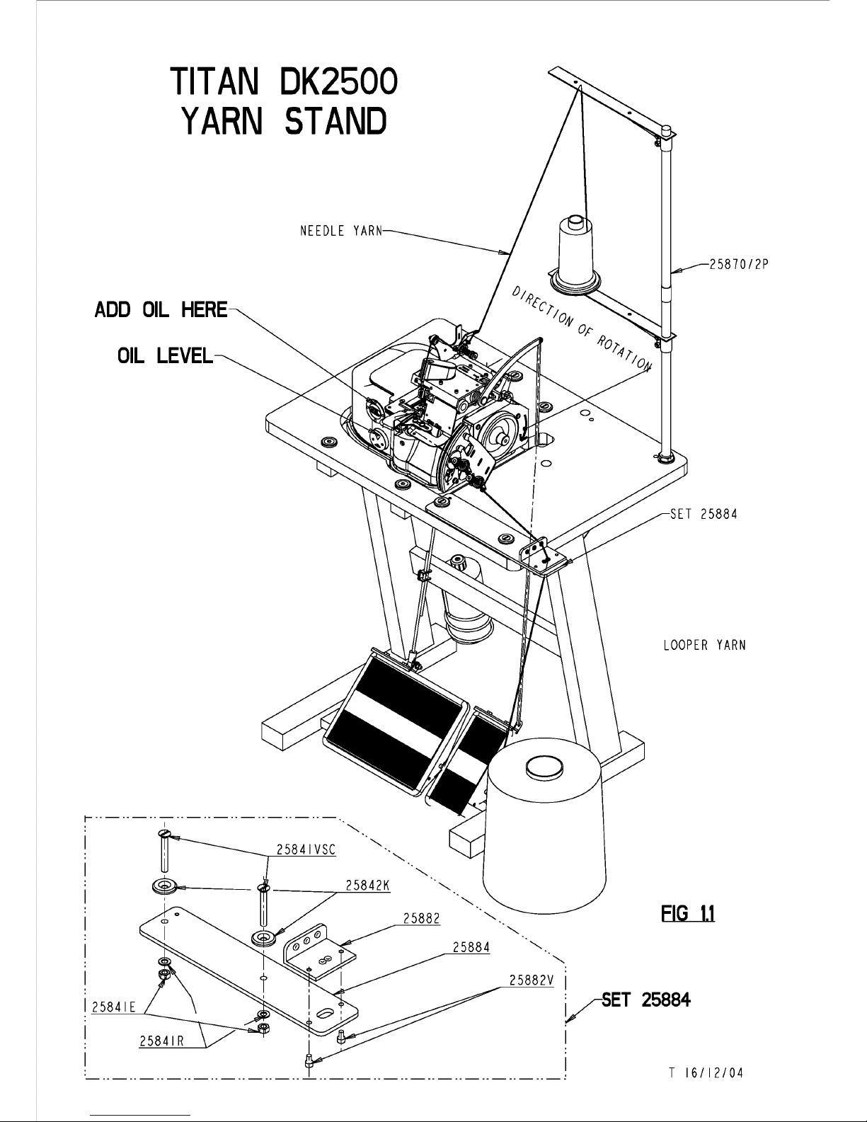
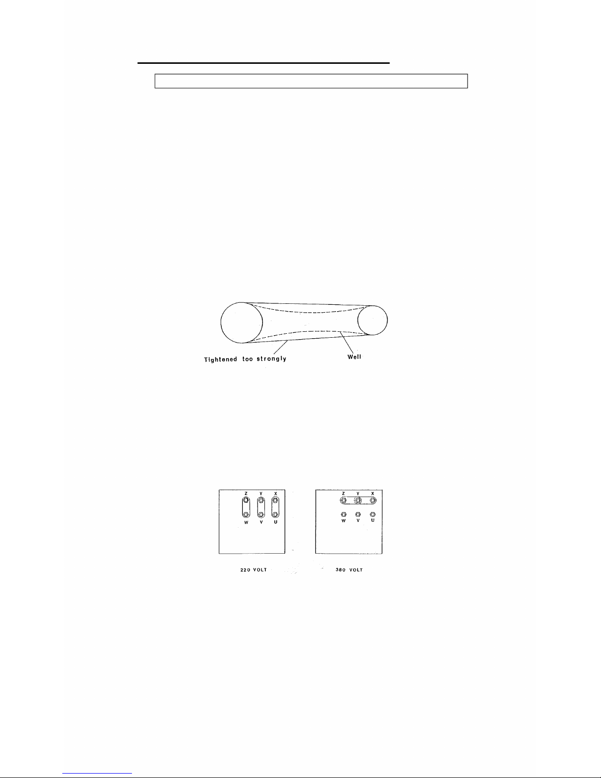
a. Complete machine - with motor and table.................................................................................3
b. Sewing head only .......................................................................................................................5
2. LUBRICATING THE SEWING HEAD....................................................................................................5
Chapter 2: Threading
1. TYPES OF YARNS.............................................................................................................................7
a. Needle yarn................................................................................................................................7
b. Chain yarn .................................................................................................................................7
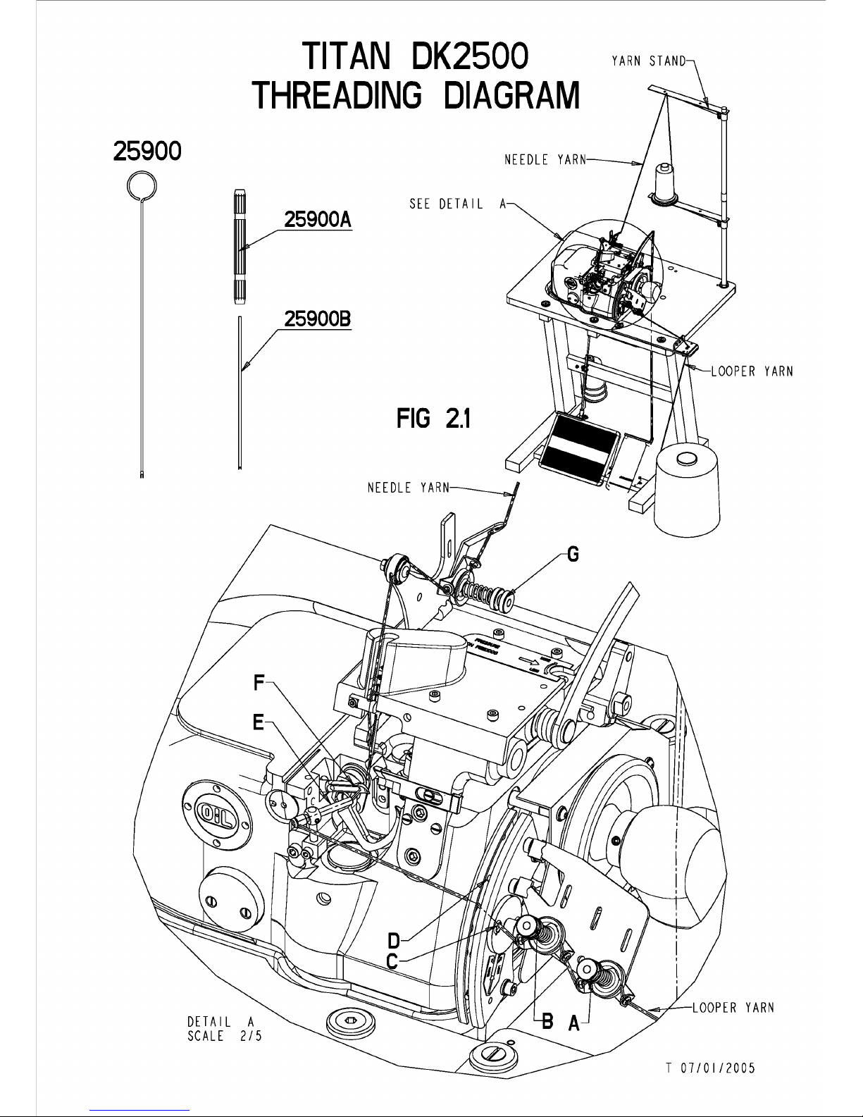
2. THREADING ....................................................................................................................................7
a. Needle thread.............................................................................................................................7
b. Chain yarn .................................................................................................................................7
Chapter 3: Stitch formation
1. CHAIN YARN FEED ..........................................................................................................................9
2. Stitch density setting......................................................................................................................11
a. On standard equipment............................................................................................................11
b With the stitch density regulator...............................................................................................11
Chapter 4: Mechanic adjustment of the sewing head
1. TYPES OF NEEDLES .......................................................................................................................13
a. How often are the needles to be replaced?..............................................................................13
b. Needle replacement..................................................................................................................13
c Needle height adjustment ..........................................................................................................15
d. Replacing the needle bar and adjusting the needle height ......................................................15
2. UPPER LOOPER..............................................................................................................................17
a. Preparatory work.....................................................................................................................17
b. Replacing the upper looper .....................................................................................................17
c. Upper looper fine adjustment...................................................................................................17
3. THE LOWER LOOPER .....................................................................................................................19
a. Preparatory work.....................................................................................................................19
b. Replacing the lower looper......................................................................................................19
c. Adjusting the upper looper to the lower looper .......................................................................21
d. Adjusting the distance between needle and lower looper........................................................21
4. THE CUTTING MOTION...................................................................................................................23
a. Renewing the upper knife.........................................................................................................23
b. Renewing the lower knife.........................................................................................................23
c. Knife fine adjustment ...............................................................................................................23
d. Aligning the lower blade with the needle plate........................................................................23
5. THE PRESSER FOOT ................................................................................................................. 23-25
6. FEED-DOG.....................................................................................................................................26
7. CHAIN GUIDE ................................................................................................................................27
8. STITCH PLATE FINGER ...................................................................................................................27
Chapter 5: Maintenance schedule
Maintenance schedule........................................................................................................28
From the Library of Superior Sewing Machine & Supply LLC

TIT
AN
DK2500
YARN
STAND
ADD
OIL
HERE
OIL
LEVEL
i------------------------------.
I
·-........_
25841VSC
@a,...___
25841E
25841R
2587012P
LOOPER
YARN
25882
........._
FIG
1.1
2
5884
........._
25882V
I
vsET
25884
I
I T 16/12/04
From the Library of Superior Sewing Machine & Supply LLC

Chapter 1: Installation and lubrication
1. Installation
a. Complete machine - with motor and table
For units, supplied complete with motor and table, use FIG 1.1+1.4
1. Mount the yarn-stand 25850/2P en screw it on the table.
2. Mount the yarn guide plate SET 25884 on the table.
3. Place the black rubber anti-vibration blocks(25840) in the aluminium holders .
4. Take the TITAN DK 2500 machine out of its box. TAKE CARE NOT TO LIFT UP
the machine by holding the UPPER PARTS. Instead, place your hands
underneath the closing plate of the machine, and lift the machine. Place the 3
little feet attached at the lower plate, precisely in the black rubber blocks.
5. Look underneath the table, and loosen the nut of the motor, with a flat key of 24.
This allows the motor to rotate upwards or downwards .
6. Push with one hand the motor upwards, and place the driving belt (attached to
the sewing machine) (M10012) around the pulley of the motor. Push the motor
down to stretch the belt slightly as seen in FIG 1.2.
FIG 1.2
7. Unscrew the cover marked “OIL” on the machine. Take the two oil bottles out of
the box and fill the machine with 1.5 L oil. Check if sufficient oil has been added
by looking at the oil-level glass. The oil level should be exactly between the two
red arrows. Close the cover again.
The electric motor is supplied, connected for use on 380V/3 PHASE supplies. For use
on 220V/3PH supplies, use the connection diagram (FIG 1.3). Connect the cores of
the mains to the receptacles of a plug designed for local operation (not included).
Verify that the direction of rotation is correct (FIG 1.1).
FIG 1.3
-----------
--------
---
--
Tightened
too
strongly
Well
Z Y X z y X
~ ~
f@1
bl
bl
bl
~
(~
~
@ @ @
w V u w V u
220
VOLT
380
VOLT
From the Library of Superior Sewing Machine & Supply LLC

TIT
AN
DK25OO
ELECTRONIC
MOTOR
ADD
OIL
HERE
OIL
LEVEL
YARN
STAND
i------------------------------.
I
·-........_
25841VSC
@a,...___
25882
........._
2
5884
........._
FIG
1.4
25882V
I
25841E
vsET
25884
25841R
I
I T 16/12/04
2587012P
From the Library of Superior Sewing Machine & Supply LLC

b.
Sewing head only
The sewing
head
requires a drive motor that must meet the following specifications:
motor rating¾
HP
and
rated
load
speed 2.800
rpm.
Use a pulley
80
mm
in
diameter
to
match the V
belt.
Verify direction ofrotation (FIG 1.1)
Prior
to
starting
the
sewing machine, always make sure
to
pour about 1,5 Iof
oil
into
the machine.
See previous paragraph for more information about this.
I
2.
Lubricating the sewing head
Utilising splash lubrication, the sewing head
is
designed for optimum lubrication of
all
the components concerned.
To
get the maximum performance, never
run
the
machine with oil level lower
than
the minimum level
line.
The sight-glass allows quick
determination of
the
oil level (see
FIG
1.1+1.4).
ATTENTION: the machine should NEVER RUN WITHOUT
OIL.
The machine will loose daily a small amount of
oil.
An
inspection at periodical intervals
is
recommended. Ifrequired, refill the oil reservoir
by
unscrewing the filler
plug
marking OIL just above the sight-glass.
Very important: oil type SP68.
The type of
oil
to
be
used
in
this sewing machine should
be
offollowing viscosity:
SP68.
Recommended
oil
types: CASTROL-ALPHA SP68 or any similar
oil
grade.
ATTENTION:
Use
oflow-viscosity oils
will
result
in
poor lubrication properties
and
excessive wear, which
in
turn will necessitate early renewal ofthe internal parts.
Conversely, use of high-viscosity oils
will
lead
to
lines clogging, which
in
turn will
necessitate early renewal ofthe spare parts from lack of lubrication.
VERY IMPORTANT:
OIL
should
be
completely removed
and
new oil should
be
added
(1.5
I.)
ONCE A MONTH. This is best done after a
few
hours
of
operation
Remove the
plug
for oil draining underneath the machine
and
let the oil leak
in
a
bucket. Replace the
plug
and add
new oil (1.5
I)
through the
plug
marked
OIL.
If
the oil
is
strongly polluted, it
is
recommended
to
remove
the
cover underneath the
machine
and
to
remove
all
excess deposit, which has accumulated
on
the cover.
Change the gasket (25839J)
and
close the cover. Place the machine
on
the table
and
refill the machine with oil as described above.
From the Library of Superior Sewing Machine & Supply LLC

25900
TIT
AN
DK2500
THREADING
DIAGRAM
DETAIL
A
SCALE
2/5
25900A
25900B
SEE
DETAIL
A
FIG
2.1
T
07/01/2005
From the Library of Superior Sewing Machine & Supply LLC

Chapter 2: Threading
1. Types of yarns
a. Needle yarn:
Many types of yarns can be used on the machine. Good results have been obtained
with following qualities : Nylon polyamide yarn of thickness 30 or 40,
Monofil (invisible) thread of 750 denier. (0,3 mm diameter) or
cotton (for example, mercerized cotton, thickness No.18).
b. Chain yarn (or “looper yarn”):
A wide range of threads can be used with DK 2500 machines.
Good results have been obtained with following qualities:
Polypropylene and Polyamide Nylon are most frequently used in thickness ranging
from 1800 detex till 5200 detex. The threads should be very lightly twined. This
gives better results after sewing, because the thread flattens out and covers the
carpet better.
Other qualities like wool, acrylic or cotton have also been used with success.
2. Threading
Remark: always switch off the motor prior to threading the yarns!
a. Needle thread
Refer to FIG 2.1 THREADING DIAGRAM for the details.
b. Chain yarn
1. Turn the hand-wheel by hand and bring the take-up Din its topmost
position. Lead the yarn thru the tension-adjusters Aand Band by hole Cthru the
plates on both sides of the take-up D.
2. Turn the hand-wheel by hand and bring the take-up Din its bottommost
position. In this position the eye of the lower looper faces the threading tube E
3. Thoroughly clean (if necessary, using the threading needle, part 25900) the
lower looper's eye.
4. Tightly wrap the chain yarn around the point of the threading needle and push it
all the way (as far as possible) into the threading tube and through the eye of the
lower looper F.
5. Gently remove the threading needle and push some more chain yarn into the
threading tube in order to obtain a small tangle of chain yarn behind the lower
looper's eye F. REMARK: Remember : remove the THREADING NEEDLE ALWAYS.
6. Turn the flying-wheel by hand to make sure the chain yarn extends above the
needle plate.
7. Make sure the needle thread remains threaded. The sewing machine is now
ready for use.
Note: For improved covering, use two or three thinner threads in the lower
looper.
From the Library of Superior Sewing Machine & Supply LLC

TIT
AN
DK25OO
STITCH
ADJUSTMENT
LOOPER
YARN
NEEDLE
YARN
LOOPER
YARN
CARPET
A:
OK
B:
NOT
OK
FIG
3.1
C:
NOT
OK
D.
NOT
OK
D J
C
H
FIG
3.2
FIG
3.3
FIG
3.4
IMITATION
3-THREADSTITCH
T
25/11/04
From the Library of Superior Sewing Machine & Supply LLC

Chapter 3: Stitch formation
1. Chain yarn feed
It is recommended to keep the pressure on the springs to a minimum on the thread
tensioners A, B and G(FIG 2.1).
Note:
Always make sure the chain yarn is positioned underneath the yarn drawing lever D
(or “take-up”) (see FIG. 2.1-3.2). Failure to do so, will result in improper stitch
formation. To avoid this, check if the machine has been threaded properly (see
chapter 2b).
FIG 3.1A: Correct stitch formation, the chain yarn and the needle thread have both
absolutely uniform tensions.
FIG 3.1B: Either insufficient chain yarn tension, or excessive needle thread tension
FIG 3.1C&D: Either excessive chain yarn tension, or insufficient needle thread tension
With the take-up lever Dcorrectly set, the amount of thread thus fed will assure
successful overlocking of the carpet.
In the event of insufficient thread feed (or with thicker carpets), however, undue
tension will be placed on the chain yarn along the edges of the carpets, which in turn
will pull the needle thread from the carpet backing (see figure 3.1C).
To remedy: adjust the take-up lever Dslightly in the direction of C3 (see figure 3.5).
Conversely in the event of excessive thread feed (or with thin carpets), the chain yarn
will be found to be slack around the carpet edges (see figure 3.1B).
To remedy: adjust the take-up lever Dslightly in the direction of C1 (see figure 3.5).
If the machine isn’t equipped with RFR fine adjustment gear (see figure 3.3), the
position of take-up lever Dis to be changed as follows:
Untighten the screw of the arm I(figure 3.2) and place the take-up lever Dinto the
wanted position (higher=less thread, lower=more thread) afterwards, tighten the
screw of arm I again.
RFR fine adjustment assembly: standard in the new machines (from 2004 on)
To adjust the thread feed : loosen the screw J (FIG 3.3). Push the bar (lever)
towards “+” to increase thread feed, towards “-“ to decrease thread feed.
Note: For the typical two-thread overlock stitch, insert the chain yarn in the Ceye as
illustrated in figure 3.2 and 3.3
For special stitch formation similar to a three-thread stitch (see figure 3.4), pass the
chain yarn through the H eye (see figure 3.2 and 3.3) and then adjust thread feed so
that the stitch thus formed is similar to the one shown in figure 3.4.
From the Library of Superior Sewing Machine & Supply LLC

TIT
AN
DK2500
STITCH
ADJUSTMENT
STITCH
WIDTH
FIG
3.6
STITCH
ADJUSTEMENT
STANDARD
FIG
3.7
STITCH
ADJUSTEMENT
WITH
RPR
L
K
M
T
25/11/04
From the Library of Superior Sewing Machine & Supply LLC

FIG 3.5
2. Stitch density setting (per cm)
a. On standard equipment
• Unscrew and remove the big knurled screw to allow access to nut K
(FIG 3.6).
• Turn the hand-wheel by hand to secure the needle in its bottommost position.
• Holding the hand-wheel in position with your right hand, unscrew (counter
clockwise) the nut Kby ½ a turn using a M10 hex key.
• Place the nut Keither forward or backward as appropriate. Thus you will
increase/reduce stitch density per cm (see figure 3.6).
• Retighten the nut K and replace the knurled screw on the sewing head!
b. With the stitch density regulator (RPE/DK 2500 SEE OPTIONAL ATTACHMENTS)
The RPE option as illustrated in figure 3.7 is fitted on to the left-hand side of the
sewing machine.
• Loosen both L screws.
• Turn the disc Mcounter clockwise.
• By turning the adjuster screw N clockwise,you increase stitch density.
By turning the adjuster screw Ncounter clockwise,you decrease stitch density.
• For best results, we recommend to sew first on a small piece of carpet to see if
the correct amount of stitches per cm has been obtained.
• To secure the adjuster screw Ninto position, turn disc Mclockwise until it can
not move further.
• Slightly tighten both Lbolts to lock the settings.
The RPE option is designed to guarantee optimum sewing result with any carpet
quality and/or yarn thickness.
,
I
From the Library of Superior Sewing Machine & Supply LLC

TIT
AN
DK2500
NEEDLE
REPLACEMENT
&
ADJUSTMENT
X
PLACE
NEEDLEBAR
IN
HIGHEST
POSITION.
D
R
FIG
4.1
T
26/11/04
From the Library of Superior Sewing Machine & Supply LLC

Chapter 4: Mechanic adjustment of the sewing
head.
!! Remark: Always switch off the motor before adjusting whatever part of the machine !!
1. The needle
The table below is a breakdown of typical needle types.
Type: Description Suitable for:
7713/230T Standard needle Medium carpets
7713-99/230T Square pointed needle Heavy car carpets
7713-99/230TP Needle with flat holder Heavy Car carpets
7713-99/230TPC Golden needle For automatic systems DK 4600
7713-200T Medium thick needle Light carpets
7713/180T Medium thin needle Light carpets
7713/160T Thin needle Blankets
7713/130T Ultra thin needle Fabrics (butt-seamer DK 2500E
and 2510E series)
For special purposes, please contact our service department for additional information.
tel.: ++32/2-216.31.40
a. How often are the needles to be replaced?
Considering the typical up and down movement of needles on DK 2500 series sewing
machines is about 2.800 movements per minute, needles will need replacing after a
couple of days as they become blunt, thin, and the groove disappears, thus result :
false stitches.
Assuming the machine is used for one 8-hour shift, the needle will have pierced the
carpet approximately 6 million times in one week (40h). Depending on carpet quality,
we advise to replace the needle at least once a week.
b. Needle replacement
While sewing, a circle of dust will be built up around the needle holder. It is very
important to remove first any dust that may have accumulated, prior to fitting a
replacement needle! If not, dust accumulation in the needle holder may probably
modify the exact movement of the needle, which will result in false or bad stitch
formation and may drastically decrease the life time of internal parts.
From the Library of Superior Sewing Machine & Supply LLC

Needle
guide.
DK
2500.
I
HEAVY
C
ARPETSI
25559A
.
!NORMAL
CARPETS!
PART
NR.
-25559-230
-25559-200
PART
NR.
-
25559A
25559B
NEEDLE
NR.
-7713/230
-7713-99/230
-
7713
/
200
NEEDLE
NR.
-
7713
/
110
-7713/130
-
7713
/
160
- 7
713
/
180
-7713 /
200
From the Library of Superior Sewing Machine & Supply LLC

SET 25559A
Afstelling
van
de
naaldgeleiding.:..
-Stukken 25559A
en
25559B
worden
los
op
de
naaldplaat
bevestigd
met
schroef
25559V.
-Stukken 25559A
en
25559B
maximaal
openschuiven,
-
De
afstelling
gebeurt
steeds
.
met
een
nieuwe
naald.
-
We
zetten
de
risald
in
haar
onderste
dode
punt.
-
We
sluiten
stukken·25559A
en
25559B
rond
de
naald
zodat
er
geen
voorwaartse
of
achterwaartse
speling
meer
is.
-
We
schroeven,
schroef
25559V
vast.
Adjustment
of
the
needle-g~
-
Fix
parts
25559A
and
25559B
·mobile o~
the
needle
plate
_.,,
with
screw
25559V. ·
-Push
the
parts
25559A and
25559B
maximum
open.
-Adjustment
must
always
be
done
with
a new
needle.
-
Put
the·
needle
in
her
lowest
death
point,
-
Close
parts
25559A and
25559B
around
the
needle
in
such
a
way
that
there
is
no more
backward
or
forward
play.
-
Fix
the
screw 25559V.
Reglage
du
guide-aiguille.
-
Pieces
25559A
et
25559B
sont
fixees
mobile
sur
la
plaque
a
aiguille
avec
la
vis
25559V.
-
Ouvrir
lea
pieces
25559A
et
25559B
maximum.
-
L'ajustement
se
fait
toujours
avec
une
nouvelle
aiguille
•
-
Positioner
l'aiguille
a
son
point
mort
inferieur.
-Fermer
les
pieces
25559A
et
25559B
auteur
de
l'aiguille
si
bien
qu1
il
n'y
a
plus
de.
j
eu en
avant
ou
en
arriere
~
-
Serrer
la
vis
25559V,
Einstellung der nadelfuhrung.
-
Teile
25559A und 25559B
milssen Mobil
auf
die
Nadel-·
Platte
befestigt
werden
mit
Schraube
25559V
•.
-
Teile
25559A und 25559B
maximal
aufschieben.
-
Die
Einstellung
musz immer
geschehen
mit
einer
neue
Nadel
-
Setzen
Sie
die
Nadel
in
Ihre
unterste
Tode
Funkt.
-
Schlieszen
Sie
Teile
25559A
und 25559B rund
die
Nadel
sodasz
es
kein
vorwarts
oder
ri.i.ckwarts
Spiel
mehr
gibt.
-
Schraube
25559V
fest
schrauben.
From the Library of Superior Sewing Machine & Supply LLC

TIT
AN
DK2500
NEEDLE
REPLACEMENT
&
ADJUSTMENT
H
FLAT
SIDE
NEEDLE
PARALLEL
WITH
LOWER
LOOPER
5
FIG
4.2
SEE
DETAIL
A
5
FIG
4.3
w
DETAIL
A
SCALE
3/
I
LOWEST
POSITION
OF
NEEDLE
POINT
.!!!
T
07/01/2005
From the Library of Superior Sewing Machine & Supply LLC

To replace worn out or broken needles, proceed as follows:
• Loosen the screw H(see figure 4.1) and remove the needle.
• Remove accumulated dust in the needle-holder.
• Fit in a replacement needle. Make sure to position and push the new needle
fully home into the needle-holder.
• Be sure the groove of the needle faces the front and that the flat side on the
back of the needle is mounted parallel to the flat face of the lower looper S(FIG
4.2). To check this, turn the hand-wheel by hand and have the lower looper and
the needle cross.
• Retighten the screw H.
• Check the needle position according to chapter 4.1c .
c. Needle height adjustment
With the needle having reached the top of its stroke, distance between the needle
point and the needle plate must be exactly 23 mm (see figure 4.1).
For fine adjustment of the needle height:
• Loosen the screws Hfirst while holding the needles by hand (see figure 4.1).
• Push the needle against the screw F.
• If adapting screw F, you first have to unscrew the screw G.
• By turning the screw F, the needle height will be increased or reduced
(clockwise/counter-clockwise).
• Retighten the screw G and also screw H
!! The following instructions are restricted to qualified personnel only !!
d. Replacing the needle bar and adjusting the needle height.
Replacing the needle bar
• Loosen the screws Aand remove the worn out needle bar B(figure 4.1) from
clamp C.
• Loosen the screw Xand recuperate the needle holder W.
• Fit the needle holder Winto the new needle bar and tighten screw Xto secure
the needle bar.
• Place a new needle in the needle holder W.
• Check the parallelism between the needle and the needle bar. If these 2 parts
are not parallel, it is strongly advised to replace the needle holder W
• Fit the new needle bar into the holder Cand lightly tighten the screws A.
• Turn the hand-wheel by hand to place the needle at the top of its stroke
(highest position).
• In this position, the distance between the needle point and the needle plate
(25558) must be exactly 23 mm (figure 4.1).
Adjusting the needle height
• Loosen the screws A in FIG 4.1. By doing this, the holder Cwill loose its grip
on needle bar B(figure 4.1).
• The position of the needle can be adjusted to the top dead point being 23 mm.
• Retighten the screws A.
• Verify, by turning the hand-wheel by hand, if the needle is moving up and down
right in the centre of the needle plate (Fig.4.1 Detail).
Optimum needle thread loop formation setting
To achieve optimum needle thread loop formation, make sure the position of the
needle with respect to the lower looper S, is correct.
• Turn the hand-wheel by hand and bring the needle to reach the bottom of its
stroke (lowest position)
• Turn the hand-wheel a little further (see figure 4.3) until the needle has travelled
1,2mm on the upward stroke.
• In this position, the point of the lower looper should just pass behind the needle
as seen in Fig. 4.3 + Detail A.
From the Library of Superior Sewing Machine & Supply LLC

TITAN
DK25OO
UPPER
LOOPER
ADJUSTMENT
5mm
V
T
FIG
4.4
T
29/11/04
From the Library of Superior Sewing Machine & Supply LLC

2. Upper looper
a. Preparatory work
In order to replace the upper looper, the cover and some other parts have to be
removed. We strongly advise to proceed as follows:
• Loosen the two screws 25833V and remove the protective plate (25833).
• Release the pressure on the pressure foot.
• Loosen the two screws 25556V and remove the needle (7713/230T).
• Loosen the two screws 25558V and remove the needle plate (25558).
• Loosen the screw 25804VL and remove the threader unit (25804).
• Loosen the screw 25655V and remove the lower blade (25655).
• Loosen the screw 25744V and remove the feed dog (25744).
• Loosen the two screws 25700V and remove the upper looper (25705).
b. Replacing the upper looper
• Turn the handwheel by hand and push the lower looper to its furthermost
backward position. This action will give the operator access to the screws T
(FIG 4.4).
• Unscrew these and replace the worn out upper looper with a new one (25705).
• Retighten the screws T.
• Turn the hand-wheel by hand for the upper looper to reach its top of its stroke.
• Make sure the outer end of the upper looper extends for 5mm beyond the edge
of the needle, as illustrated in figure 4.4.
If this is not the case, adjust correct position via the screws Tas in figure 4.4.
c. Upper looper fine adjustment
Our sewing machines are factory-set to sewing medium quality carpets with medium
quality yarns.
When using thicker/finer yarns deviating from the factory-set typical yarn thickness,
we recommend that the position of the upper looper be adjusted as follows:
Loosen the T screws (figure 4.4) and turn the hand-wheel by hand for the upper
looper to reach the top of its stroke (highest position).
In the event of thick yarns, move the point of the upper looper a little to the left
(0,5mm maximum), so that the distance between the outer end of the upper looper
and the edge of the needle is 5,5mm.
In the event of fine yarns, move the outer end of the upper looper a little to the right
(0,5mm maximum), so that the distance between the outer end of the upper looper
and the edge of the needle is 4,5mm.
Note: With every change of the upper looper, check the following points while turning
the hand-wheel by hand:
When the upper looper Vand the lower looper S(figure 4.5) cross one another on the
upper looper upward stroke, the end of the upper looper Smust travel right in the
centre of the recess of the lower looper S.
On its upward stroke towards the needle, the end of the upper looper V, must not
touch the lower looper Sand needle (no contact is allowed). Should this occur
anyway, follow the steps below. After having adjusted the upper looper, put back all
parts and put back again the pressure on the pressure foot.
From the Library of Superior Sewing Machine & Supply LLC
Table of contents
Other Titan Sewing Machine manuals