Titan TF10WLED-FA User manual

1
TITAN
5W x 2 LED TWIN HEAD SPOTLIGHT
5
2
1
3
4
LED Light
Beam Adjustment Ring
Wall Box
Main Body
PIR (Motion Sensor)
INTRODUCTION
The Titan twin head 10W LED Spotlight offers you an
economical lighting solution with extremely low energy
consumption.
During darkness, the built-in passive infrared (PIR)
sensor turns on the Spotlight when the PIR sensor
detects a moving heat source in its coverage area. During
daylight, the built-in photocell sensor saves energy by
deactivating the Spotlight.
Two beam adjustable spotlights allow you to provide the
optimum lighting coverage.
Note: Read this entire manual before you start to
install the system.
SAFETY PRECAUTIONS
DO NOT install when it is raining.
Isolate the power supply before installation.
UK Building Regulations require outdoor mains
installations be carried out by a qualified electrician.
BS7671: 2008 IEE Wiring Regulations must be
complied with in all respects.
HO5RNF round flexible cable and drip loops must be
used to avoid water ingress damage to the unit.
Ensure that the power supply is protected by a 6A
circuit breaker or suitable fuse.
Ensure minimum distance of 0.5m away from lighted
objects.
The unit must be installed vertically (FIGURE 1a)
NOT horizontally (FIGURE 1b).
VERTICAL HORIZONTAL
FIGURE 1a FIGURE 1b
CHOOSING A MOUNTING LOCATION
For the best results, mount the Spotlight onto normal
brickwork 2.0m above the ground.
Avoid aiming the PIR sensor at pools, heating vents,
air conditioners or objects that may change
temperature.
Avoid pointing the PIR sensor at trees or shrubs or
where the movement of pets or animals may be
detected.
Avoid locations where direct sunlight will shine onto
the front of the PIR sensor for long periods,
deterioration of the Fresnel lens may occur leading
to poor triggering response.
Prior to mounting, keep in mind that the PIR sensor
is more sensitive to a heat source moving across its
coverage area and less sensitive to a heat source
that moves directly towards the PIR sensor
(FIGURE 2).
FIGURE 2
Select a location for the unit based on the coverage
angles shown in FIGURE 3.
COVERAGE ANGLES
FIGURE 3
180
°
1
10
°
12m
2m

2
WIRING INSTRUCTION
(1) WARNING isolate the power supply.An internal
single pole wall switch is recommended to allow
easy control of the Spotlight.
(2) Remove the wall box screw at the base of the unit (if
fitted retain the screw for later use).
(3) Detach the wall box by using a flathead screwdriver
to gently pry the wall box open. There are two clips;
one on the left side and one on the right side of the
wall box. (FIGURE 4a & 4b)
FIGURE 4a
FIGURE 4b
(4) Use a braddle to punch a small hole in the cable
grommet, enabling the supply cable to enter the wall
box.
(5) Route the supply cable through the cable grommet.
A drip loop is required between the wall box and the
wall to avoid water ingress.
(6) Determine the correct location to mount the Spotlight.
Use the wall box as a template to mark the fixing
holes on the wall. Drill the holes and insert the
plastic wall plugs supplied. Fix the wall box using the
screws provided. (FIGURE 5)
FIGURE 5
(7) Strip approximately 6-8mm of inner core insulation
from the supply cable.
(8) Connect the BROWN wire (Live wire) to the terminal
marked “L”.
Connect the BLUE wire (Neutral wire) to the terminal
marked “N”. (FIGURE 6)
NB: The Spotlight is double insulated no earth is
required.
Fix the Cable Fastener into place to secure the cable.
(FIGURE 6)
AC POWER
LIVE
NEUTRAL
Cable Fastener
FIGURE 6
(9) Refit the Spotlight onto the wall box and secure with
the two clips. Refit the wall box screw at the base of
the unit (if fitted).
Note: If you need to detach the Spotlight from the wall
box. WARNING isolate the power supply. Remove the
wall box screw at the base of the unit (if fitted). Detach
the wall box by using a flathead screwdriver to gently pry
the wall box open. There are two clips; one on the left
side and one on the right side of the wall box. (FIGURE 7).
Support the fitting during the process to prevent it from
falling.
1
2
FIGURE 7
ANGLE ADJUSTMENTS
The LED spotlight heads can be adjusted up to 45° left
and 45° right. The PIR sensor can be adjusted up to 45°
left and 45° right. (FIGURE 8a)
FIGURE 8a
The LED spotlight heads can be adjusted 37.5° vertically.
The PIR sensor can be adjusted vertically 35°
(FIGURE 8b)

3
FIGURE 8b
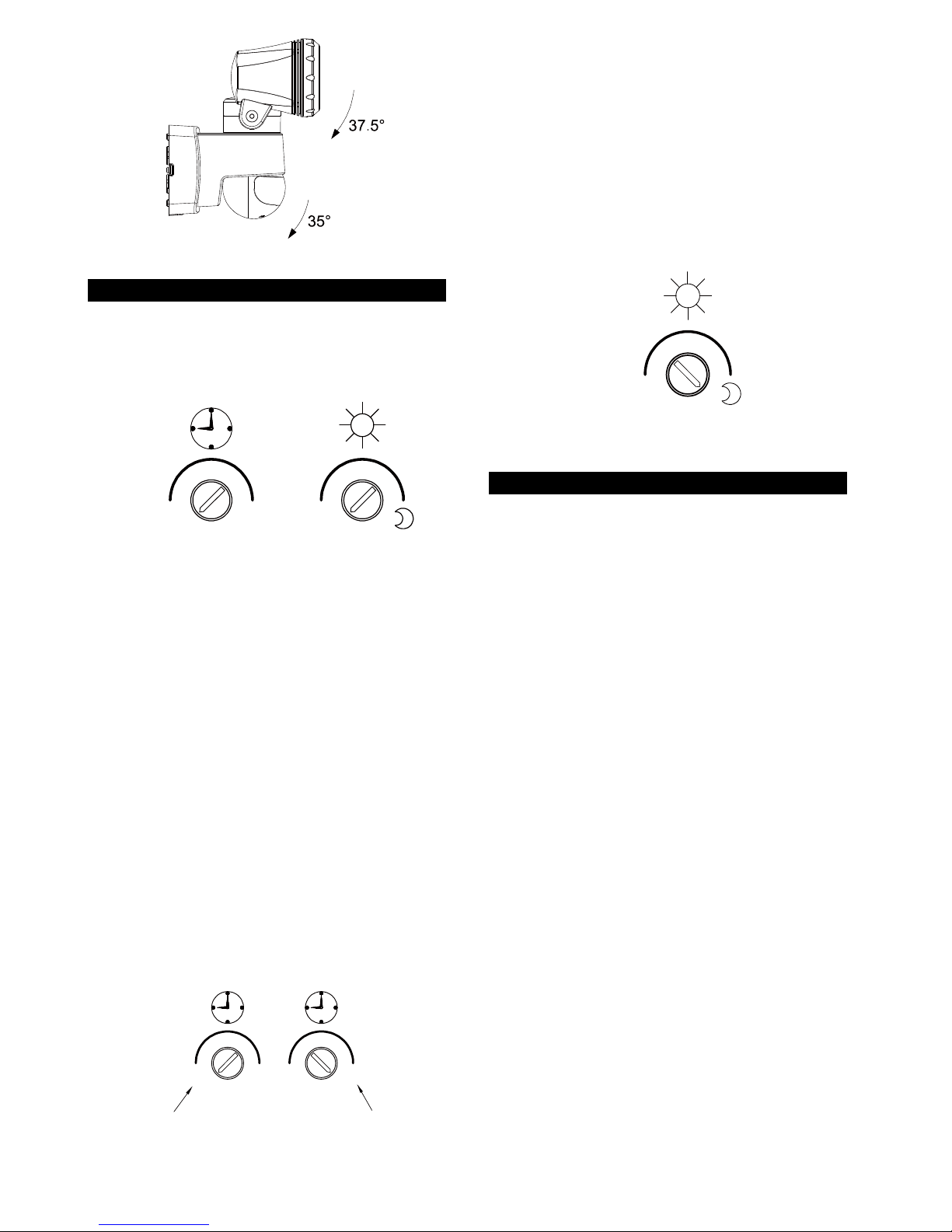
SETTING THE LIGHTING SYSTEM
(1) TEST MODE
Turn the LUX control and the TIME control
counterclockwise to the TEST position. (FIGURE 9)
T+T
FIGURE 9
Turn on the wall switch. The unit will start warm up
sequence for about 60 seconds. After warm up it will
automatically revert to automatic operation. During
the warm-up period the lights will stay on.
Walk through the detection area. The lights turn on
when you move and turn off when you stop. Wait
until the lights turn off and then move again to test
the sensor.
Adjust the motion sensor to cover the desired
detection area. For a smaller coverage area, tilt the
sensor down; for a larger coverage area, tilt the
sensor up.
(2) TIME ADJUSTMENT
The TIME adjustment controls how long the light will stay
on after motion has been detected.
Turn the TIME control clockwise to increase (up to 12
minutes) the time the lights stay on for or counter
clockwise to decrease (down to 5 seconds) the time the
lights stay on for. (FIGURE 10)
About 12 minutesAbout 5 seconds
T+T+
FIGURE 10
(3) LUX ADJUSTMENT
The LUX control determines the ambient Lux level the
lights will turn on when the sensor is in automatic
operation.
The Lux level can be set between 30 and 200 Lux. Turn
the LUX control clockwise to the MOON position and the
lights will only turn on at night (below 30 Lux). Turn the
LUX control knob counterclockwise to increase the Lux
setting. Set the control to suit your requirements.
(FIGURE 11)
T
FIGURE 11
OPERATION
Depending on your requirements you can switch the unit
between the following operation modes: Automatic
Operation and Manual Override.
(1) Automatic Operation
Turn on the wall switch. After about 60 seconds warm up
the PIR sensor will enter automatic operation. When the
PIR sensor detects a moving heat source and the
ambient light level is lower than the LUX setting, the lights
will automatically turn on. The lights will stay on for the
duration of the TIME setting and then turn off. Note that if
another moving heat source is detected while the lights
are still on, the timer will restart.
(2) Manual Override
To keep the lights on regardless you can override the
automatic operation. To enable manual override mode,
first ensure that the lights are on and then turn the wall
switch off and on twice (off-on, off-on) within 3 seconds.
The interval between each operation must be 0.5 to 0.75
seconds.
In Manual Override mode, the lights will remain on for
around 5 hours. After 5 hours the lights will turn off and
the motion sensor will revert to automatic operation.
You can also manually set the motion sensor back to
automatic operation by turning off the wall switch for at
least 10 seconds and then turning it back on.
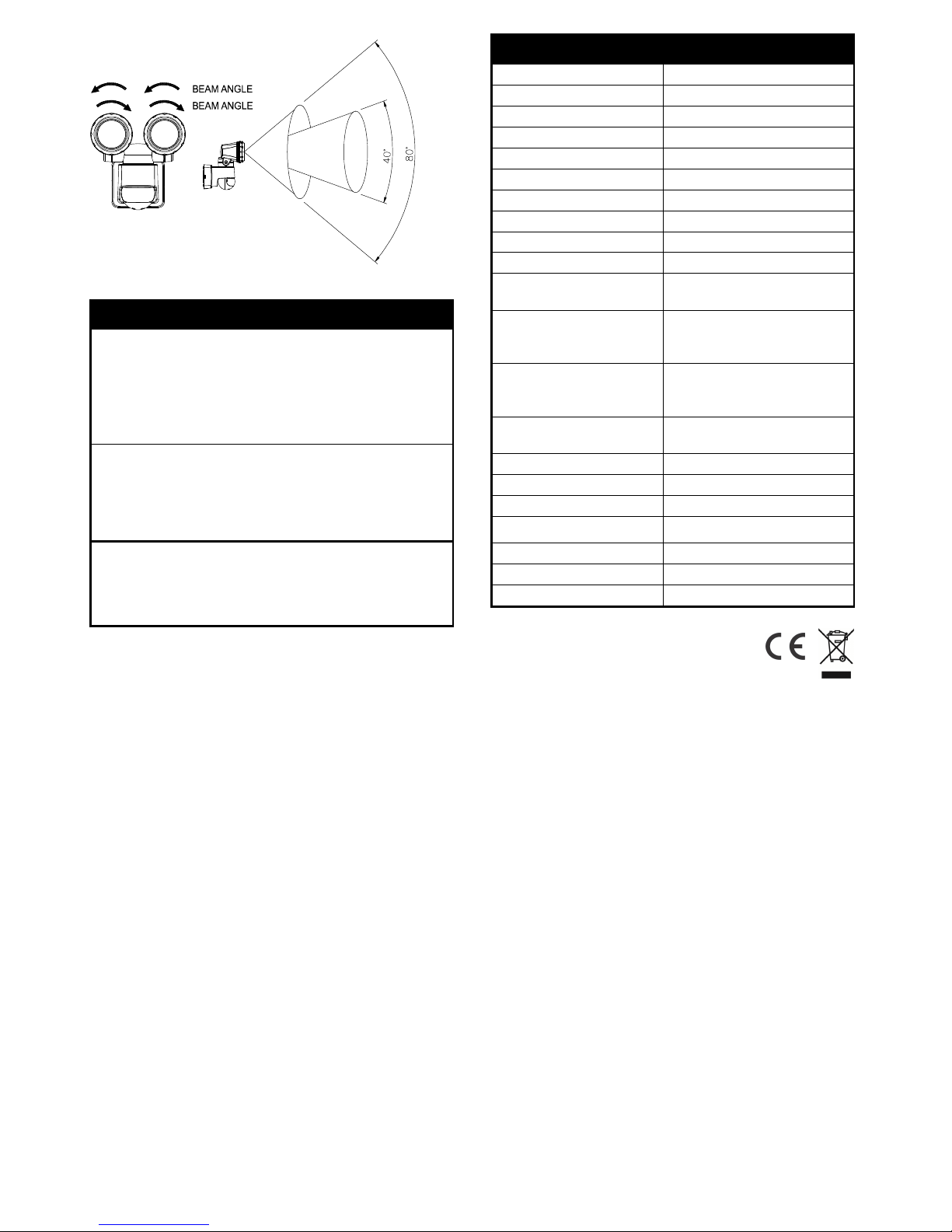
Beam Adjustment
The beam angle of the LED spotlight heads can be
adjusted by turning the Beam Adjustment Ring around
the LED spotlight heads. Adjust the beam according to
your lighting requirements. (FIGURE12)

4
40°
80°
FIGURE 12
TROUBLESHOOTING
Lights do not turn on
Make sure the wiring connection is correct.
Ensure that you are within detection range. Adjust
the PIR sensor angle if necessary.
Adjust the LUX control knob by turning it
counterclockwise.
Lights remain on
Make sure the wiring connection is correct.
Adjust the TIME control knob by turning it
counterclockwise.
Make sure that the unit is not in Manual Override mode.
Others
Check with your electrician who did the installation.
SPECIFICATIONS
*
Power Requirement
AC
220
-
240V / 50Hz
Lighting Load
10W
(5W x 2) LED
Standby
power usage
0.5W
LED
Cree
XBD x 4
Color Temperature (K)
5000K
CRI
>7
0
Lumen (
lm
)
U
p to 550lm (275lm x 2)
Beam Adjustment
Angle
4
0° ~80°
L70 Life Span (hours)
U
p to
30000 hr
Detection Angle
Up to 180° at 2m Height
Detection Range
U
p
to 12m (39.4ft) at 2m
Height
PIR Sensor Adjustment
Angles
Up to
45
° Left
Up to 45° Right
Up to 3
5
°
Vertical
Spotlight Heads
Adjustment Angles
Up to 45
o
Left
Up to 45° Right
Up to 37
.5
°
Vertical
Mounting Height
Recommended 2m
Brick
Wall Mount
Time Adjustment
5
seconds
-
12
minutes
Lux Adjustm
ent
30
-
20
0 Lux
Operation Mode
Auto/Manual override
Warm Up Time About 60 seconds
Working Temperature
-
2
0
°
C
-
+4
0
°
C
Protection Class
Class I
I
Double Insulated
IP Protection
IP44
*Specifications are subject to change without notice.
TITANTF10WLED-FA 2014/10
Environmental Concerns:
Please DO NOT dispose of electrical appliances as
unsorted waste, use the recycling facilities provided by
your local authorities.
Please DO NOT dispose of packaging as unsorted waste,
use the recycling facilities provided by your local
authorities.
Popular Spotlight manuals by other brands

Honeywell
Honeywell Ex-Or MS2421PF quick start guide

Silverline
Silverline 282556 manual

Havis-Shields
Havis-Shields CD-PULS500 instruction manual

Home Zone Security
Home Zone Security LK48498V installation instructions

Lumascape
Lumascape Centria C4 installation instructions

Home Zone Security
Home Zone Security ELI0857V installation instructions