TitanGPS CP2 User manual
CALL TO TESTTHE DEVICE BEFORE CLOSING UP
DASH. FAILURE TO FOLLOW INSTRUCTIONS MAY
DAMAGE EQUIPMENT AND VOID WARRANTY
CERTIFIED
TRACKING
SOLUTIONS
1.780.391.3800
TOLL FREE 1.855.287.4477 (CTS4GPS)
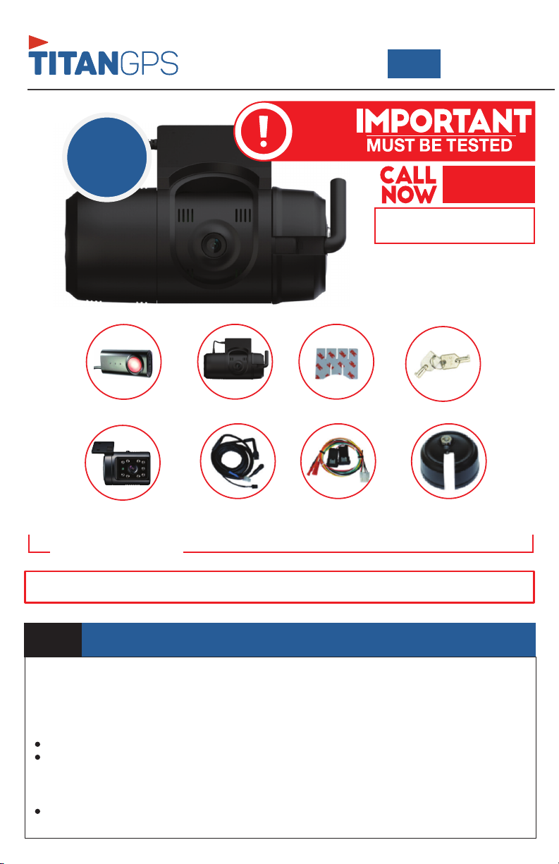
PACKAGE CONTENTS
12-24V
Power Specifications | Input: DC 10~32V, 2000mA Output: DC5V, 2500mA
QUICK INSTALL
GUIDE
CP2
POWER ADAPTER WIRING HARNESS LOCKING COVER
ADHESIVE TAPE
KP1S CAMERA LOCKING COVER KEYS
SECONDARY CAMERA (OPTIONAL)
REMOTE CONTROL
STEP 1 MOUNT CAMERA(S)
The CP2 can accommodate up to two cameras. These can be a combination of indoor and/or
outdoor cameras. We recommend consulting with the client as to their preferred mounting
location(s) and camera angles(s). Please see below for some mounting suggestions;
Windshield mounting:
a) Preparation
Ensure glass is clean and dry.
Glass temperature should not be too hot or cold (between 50F (10C) and 80F (27C).
b) Mounting
Open the locked camera cover using the provided security key. [Turn the key and depress the
black button on the cover]
Adjust bracket by rotating to the desired angle. Important! Remove protective film from camera
lens.(if applicable)

Attach the provided 3M adhesive pad to the bracket and press firmly. [Ensure glass is clean and
dry BEFORE attaching]
Secure to windshield behind the rear view mirror as high on the windshield as possible but still
within the windshield wiper zone. FMCSA mandates the camera portion of the device should
reside within the top 2 inches of the vehicle wiper sweep. [Hold firm pressure for 30 seconds].
Other mounting:
Ensure camera is firmly mounted in a position that will give the client the required camera angle.
Important! Tighten the security screws to lock position (if applicable).
Recommend mounting in a position where camera lens will stay as clean as possible.
Wiring Connections:
Confirm with the client as to which optional connections are required. Required connections
include Power, Ground and Ignition. Optional connections are listed below.
Other mounting Locations:
Select an appropriate location as per the clients direction, and mount the camera. Be sure to
orient the camera with the correct side facing up
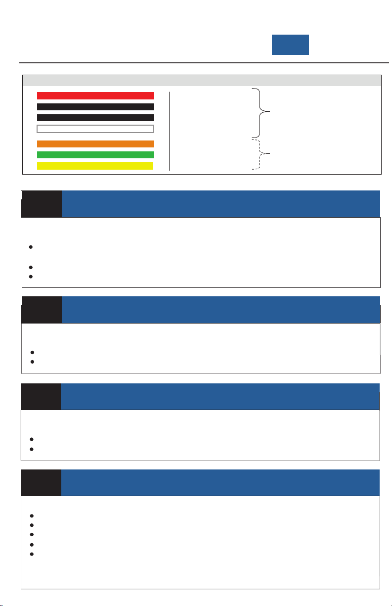
STEP 2 CONNECT IGNITION
In order to function properly the device needs to be connected to a suitable "True" Ignition source.
This source has battery voltage whenever the vehicle is turned on and zero volts whenever the
vehicle is turned off.
This source does NOT drop in voltage during crank.
Connect the White wire of the 8 pin wiring harness to this ignition source.
STEP 3 CONNECT CONSTANT POWER
The device requires a minimum 12V constant (Battery Power) on this line to function. (Max 24v)
Do not remove/bypass the fuse.
Connect the Red wire of the 8 pin wiring harness to this constant source.
STEP 4 CONNECT GROUND
For best results, create a new connection to bare-metal chassis ground
Do not use a shared ground or supplied ground from any module or device.
Connect the Black wire of the 8 pin wiring harness to this ground.
STEP 5 ROUTE AND CONNECT HARNESSES
Ensure the vehicle is turned off before connecting any harnesses
Route main power cable from CP2 camera to in-dash location
Connect the right-angled power cable to CP2 camera
Connect the white 6 pin from the wiring harness to the INT1-T power adapter box
Ensure the INT1-T power adapter is in the “ON” position
Connect the white 8 pin from the wiring harness to the INT1-T power adapter box
Power (BAT+)
Ground (BAT-)
Ground (BAT-)
Ignition (IGN+)
Alarm in 1 (12v)
Alarm in 2 (NC/NO)
Alarm Out
Wiring Harness Diagram
Required
Optional
QUICK INSTALL
GUIDE
CP2
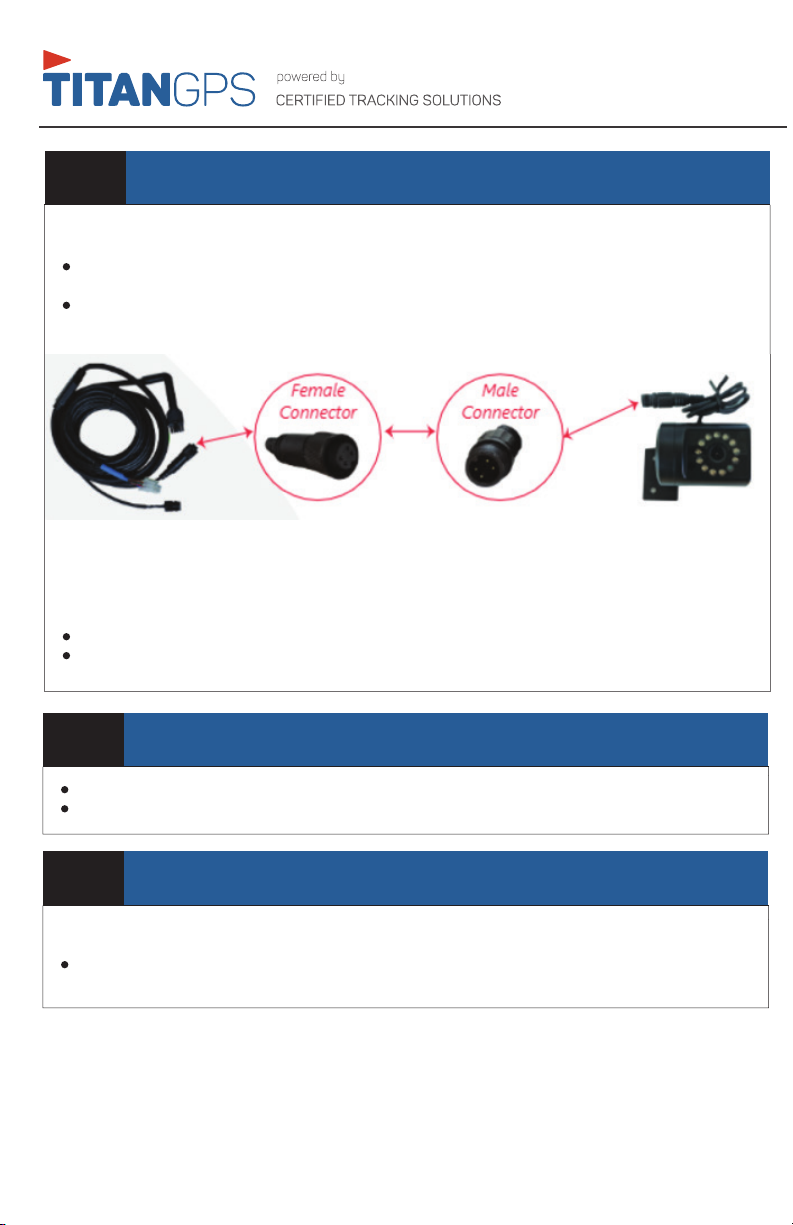
STEP 6 OPTIONAL COMPONENTS (SECONDARY CAMERA AND/OR REMOTE CONTROL)
Secondary Camera (Optional)
The CP2 can be used with many different types of secondary cameras.
Route and Connect the round barrel connector on the main CP2 power adapter cable to the
camera input cable.
Secure the secondary camera in a position where it will provide the desired video angle. We
recommend.
Remote Control (Optional)
The CP2 has an optional Remote Control to tag events. We recommend consulting with the client as
to their preferred mounting location.
Prepare surface and affix the Remote Control onto dash within reach of the driver.
Route, mount and connect Remote Control to the CP2 main power adapter cable.
STEP 7 INITIAL STARTUP
Start Vehicle, LEDs should illuminate
Wait up to five minutes until both the Green and Blue lights are solid
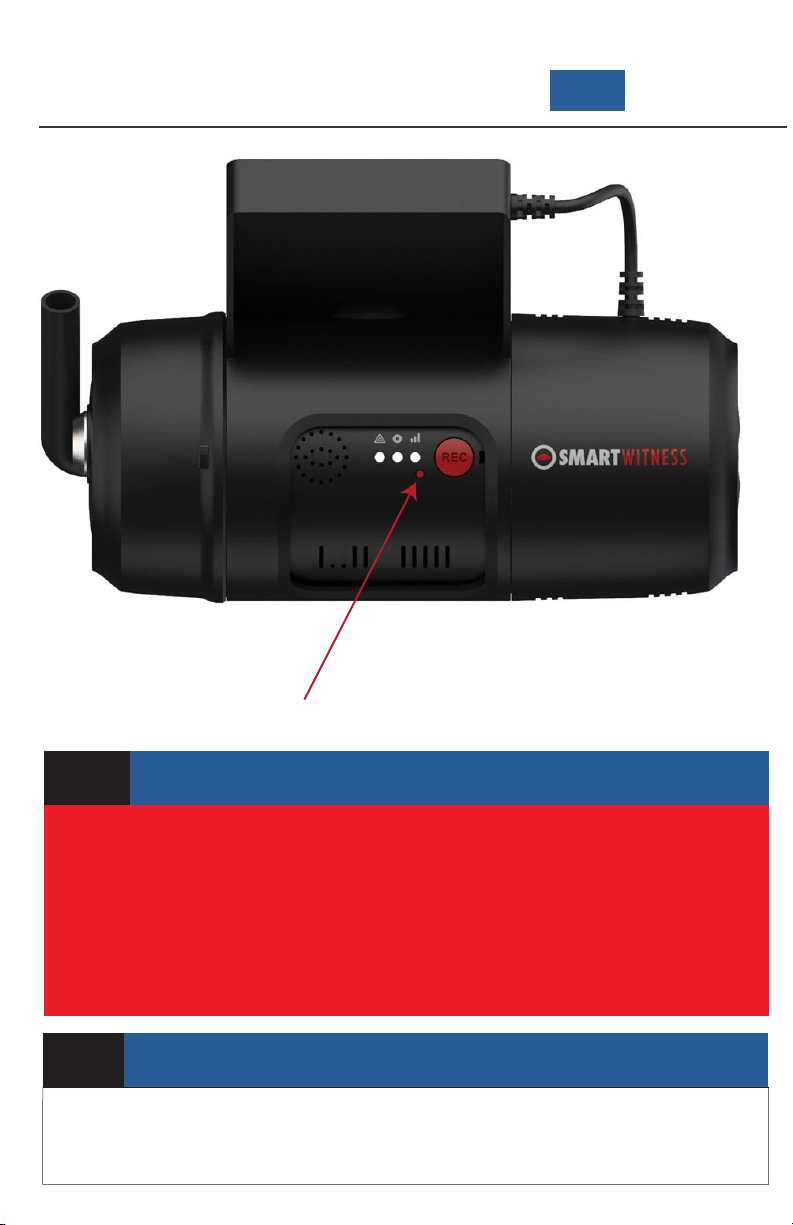
STEP 8 G-SENSOR CALIBRATION
With the vehicle running on a flat surface and both LEDs solid, press the G-Sensor Calibration button
once (small red button to the left of the “REC” button).
There will be a beep and the CP2 LED light will blink briefly to indicate the G-Sensor calibration
has registered.
STEP 9 TEST
To TEST the device, call us NOW!
G-Sensor Calibration
STEP 11
Give the provided keys and any extra parts/accessories to the fleet owner/administrator
ADMINISTRATIVE DETAILS
QUICK INSTALL
GUIDE
CP2

QUICK INSTALL
GUIDE
CP2

1.780.391.3800
TOLL FREE 1.855.287.4477 (CTS4GPS)
powered by: Certified Tracking Solutions
Table of contents
Other TitanGPS Dashcam manuals


