Titanium 59403 User manual

Visit our website at: http://www.harborfreight.com
WELDING
TABLE
59403
Owner’s Manual & Safety Instructions
Save This Manual Keep this manual for the safety warnings and precautions, assembly,
operating, inspection, maintenance and cleaning procedures. Write the product’s serial number in the
back of the manual near the assembly diagram (or month and year of purchase if product has no number).
Keep this manual and the receipt in a safe and dry place for future reference. 23f
When unpacking, make sure that the product is intact
and undamaged. If any parts are missing or broken,
please call 1-888-866-5797 as soon as possible.
Copyright©2021 by Harbor Freight Tools®. All rights reserved.
No portion of this manual or any artwork contained herein may be reproduced in
any shape or form without the express written consent of Harbor Freight Tools.
Diagrams within this manual may not be drawn proportionally. Due to continuing
improvements, actual product may differ slightly from the product described herein.
Tools required for assembly and service may not be included.
Read this material before using this product.
Failure to do so can result in serious injury.
SAVE THIS MANUAL.

Page 2 For technical questions, please call 1-888-866-5797. Item 59403
Specifications
Table Surface 36″ x 24″
Table Height 33-1/4″
Maximum Weight Capacity 600 lb
Hole Diameter 5/8″
Hole Spacing 2″
IMPORTANT SAFETY INFORMATION
Assembly Precautions
1. Assemble only according to these instructions.
Improper assembly can create hazards.
2. Wear ANSI-approved safety goggles and
heavy-duty work gloves during assembly.
3. Keep assembly area clean and well lit.
4. Keep bystanders out of the area during assembly.
5. Do not assemble when tired or when under the
influence of alcohol, drugs or medication.
6. Weight capacity and other product capabilities apply
to properly and completely assembled product only.
Use Precautions
1. This product is not a toy. Do not allow
children to play with or near this item.
2. Use as intended only. Do not sit or stand on Table.
3. Inspect before every use; do not use
if parts are loose or damaged.
4. Use only on flat, level, hard surface.
5. Do not exceed listed weight capacity. Tighten
all knobs securely before applying load.
Be aware of dynamic loading!
Sudden load movement may briefly create
excess load causing product failure.
6. Maintain product labels and nameplates.
These carry important safety information.
If unreadable or missing, contact
Harbor Freight Tools for a replacement.
Page 3For technical questions, please call 1-888-866-5797.Item 59403
Assembly Instructions
Read the ENTIRE IMPORTANT SAFETY INFORMATION section at the beginning of this document
including all text under subheadings therein before set up or use of this product.
Note: For additional information regarding the parts listed in the following pages,
refer to the Assembly Diagram near the end of this manual.
Unwrap and separate all parts on a clear work area.
Tabletop Only Configuration
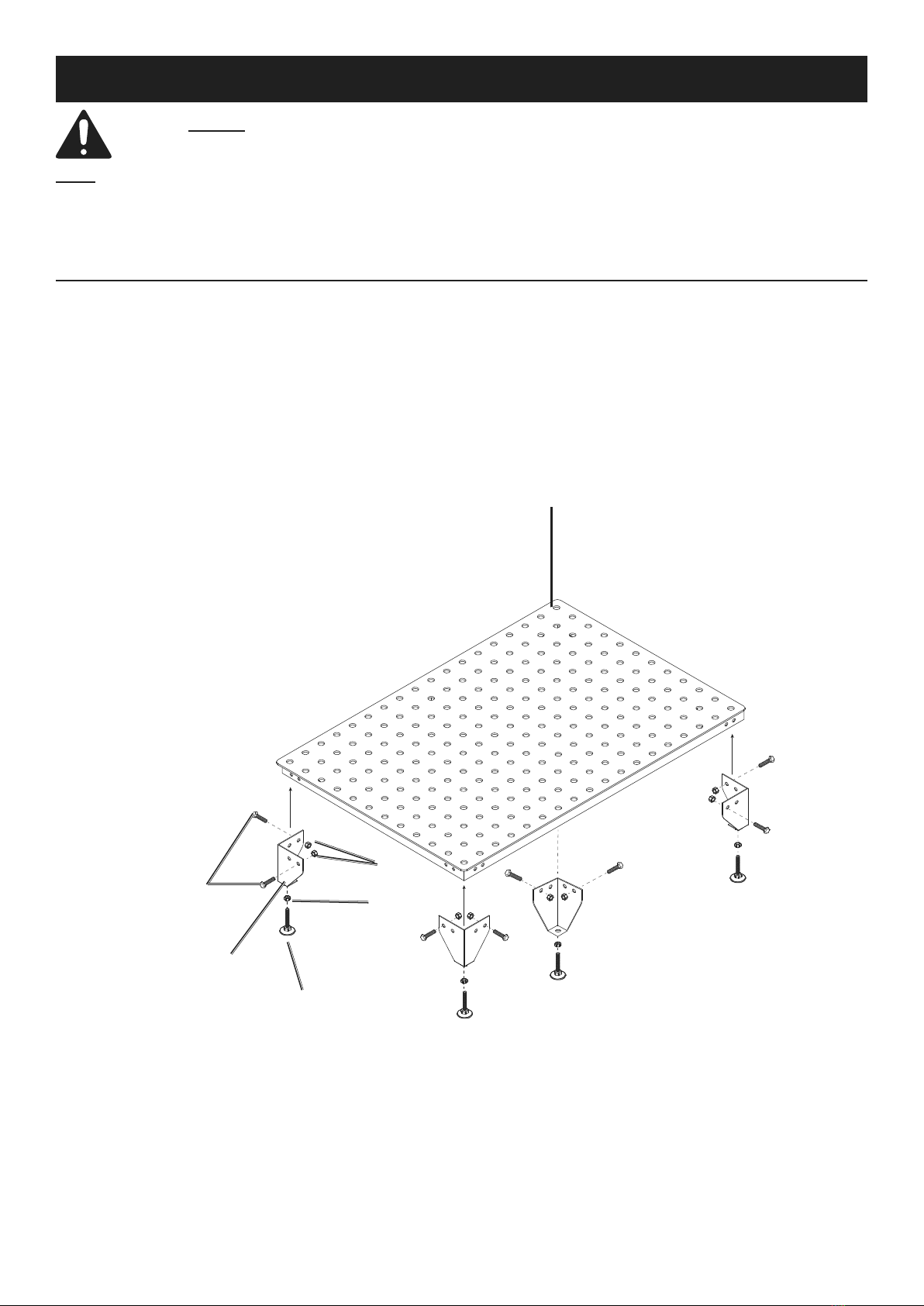
1. Attach the four Short Legs (2) to the Tabletop (1).
Screw two Bolts (6) into the outermost holes on each
Short Leg. Secure with Nuts (7). See Figure A.
2. Screw the four Leveling Feet (5) into the
bottom hole on each Short Leg. Leave Nuts
(8) loose for now. Place the Tabletop Assembly
in the upright position, and adjust the Leveling
Feet as needed to level the Tabletop.
3. When the Tabletop (1) is level, turn it upside
down again, and tighten all four Nuts (8) to
lock the Leveling Feet (5) into position.
Tabletop (1)
Nut (7)
Short
Leg (2)
Leveling
Feet (5)
Nut (8)
Bolt (6)
Figure A: Tabletop Configuration
Page 4 For technical questions, please call 1-888-866-5797. Item 59403
Full Assembly Configuration
1. Attach the four Short Legs (2) to the Tabletop
(1). Screw two Bolts (6) into the outermost
holes on each Short Leg. Secure with
Nuts (7). See Figure A on page 3.
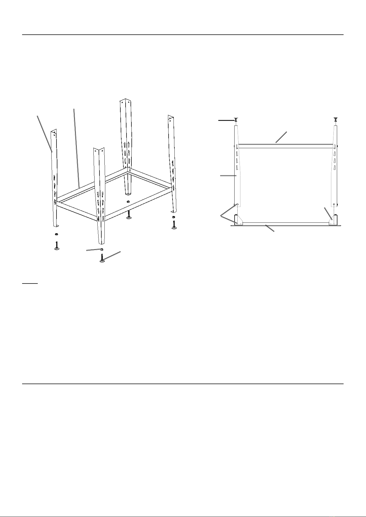
2. Connect Leg Brace (4) to the Long
Legs (3) using the holes in the middle
of the Long Legs (3). See Figure B.
Leg Brace (4)
Long
Leg (3)
Leveling
Foot (5)
Nut (8)
Figure B: Leg Brace (4) Attachment
Note: Use the same height holes on each Long Leg
(3) to make sure the Leg Brace (4) will be level.
3. Place the Tabletop (1) upside down on
a sturdy surface. Set the Leg Assembly
over the Tabletop (1) and align the
mounting holes on the Long Legs (3)
with the mounting holes on the Short
Legs (2). Use two Bolts (6) and Nuts
(7) to secure each Long Leg (3) to
the Table Top assembly. Tighten the
Bolts (6) and Nuts (7). See Figure C.
Leveling
Foot (5)
and Nut (8)
Long
Leg (3)
Leg Brace (4)
Short
Leg (2)
Tabletop (1)
Mounting
Holes
Figure C: Securing Leg Assembly to Tabletop (1)
4. Screw the four Leveling Feet (5) into the
bottom hole on Long Leg (3). Leave Nuts (8)
loose for now. Place the Tabletop Assembly in
the upright position, and adjust the Leveling
Feet as needed to level the Tabletop.
5. Place the assembled table in the upright
position. Adjust the Leveling Feet as
needed to level the table. When the
Table Top is level, turn it upside down
again, and tighten the Nuts (8) to lock
the Leveling Feet into position.
6. When the Tabletop (1) is level, turn it upside
down again, and tighten all four Nuts (8) to
lock the Leveling Feet (5) into position.
Tools and Tool Mounting
1. Tools can be mounted to Tabletop (1) in any
configuration. Make sure all tools are properly
attached and secured before beginning work.
2. Clamp: Insert Clamp (14, 11) into
any hole on Tabletop (1). Clamp may
be used to secure workpiece.
3. Stop Bar: Mount Stop Bar (9, 11, 15) into
any hole on Tabletop (1). Use Stop Bar to
guide or stop workpiece. Use in conjunction
with Threaded Adaptors (12).
4. Threaded Adaptors: Mount Threaded Adaptors
(12) underneath Tabletop (1). Use to convert
any Tabletop hole into an M10 threaded hole.
5. V-Blocks and V-Spacers: Place V-Spacer
(13) into any hole on Tabletop (1), then place
V-Block (10) on top of V-Spacer(13). Use to
support rounded workpieces or parts.

Page 5For technical questions, please call 1-888-866-5797.Item 59403
Maintenance
Inspection, Maintenance, and Cleaning
1. BEFORE EACH USE, inspect the general
condition of the Welding Table. Check for:
• loose hardware
• misalignment or binding of parts
• cracked or broken parts
• any other condition that may
affect its safe operation.
2. AFTER USE, wipe external surfaces
of the Table with clean cloth.

Page 6 For technical questions, please call 1-888-866-5797. Item 59403
Part Description Qty
1 Tabletop (with Bottom Frame) 1
2 Short Leg 4
3 Long Leg 4
4 Leg Brace 1
5 Leveling Foot 4
6 Bolt 16
7 Nut M8 16
8 Leveling Foot Nut M10 4
Part Description Qty
9 Stop Bars 4
10 V-Blocks 8
11 Stop Bars Cover Plate 4
12 Threaded Adaptors 4
13 V-Blocks-Spacers 4
14 Clamp 4
15 Bolt M10 8
16 Clamp Nut M12 4
Record Serial Number Here:
Note: If product has no serial number, record month and year of purchase instead.
Note: Some parts are listed and shown for illustration purposes only, and are not available
individually as replacement parts. Specify UPC 193175469311 when ordering parts.
Parts List and Diagram
PLEASE READ THE FOLLOWING CAREFULLY
THE MANUFACTURER AND/OR DISTRIBUTOR HAS PROVIDED THE PARTS LIST AND ASSEMBLY DIAGRAM
IN THIS DOCUMENT AS A REFERENCE TOOL ONLY. NEITHER THE MANUFACTURER OR DISTRIBUTOR
MAKES ANY REPRESENTATION OR WARRANTY OF ANY KIND TO THE BUYER THAT HE OR SHE IS
QUALIFIED TO MAKE ANY REPAIRS TO THE PRODUCT, OR THAT HE OR SHE IS QUALIFIED TO REPLACE
ANY PARTS OF THE PRODUCT. IN FACT, THE MANUFACTURER AND/OR DISTRIBUTOR EXPRESSLY
STATES THAT ALL REPAIRS AND PARTS REPLACEMENTS SHOULD BE UNDERTAKEN BY CERTIFIED AND
LICENSED TECHNICIANS, AND NOT BY THE BUYER. THE BUYER ASSUMES ALL RISK AND LIABILITY
ARISING OUT OF HIS OR HER REPAIRS TO THE ORIGINAL PRODUCT OR REPLACEMENT PARTS
THERETO, OR ARISING OUT OF HIS OR HER INSTALLATION OF REPLACEMENT PARTS THERETO.
Parts List
Page 7For technical questions, please call 1-888-866-5797.Item 59403
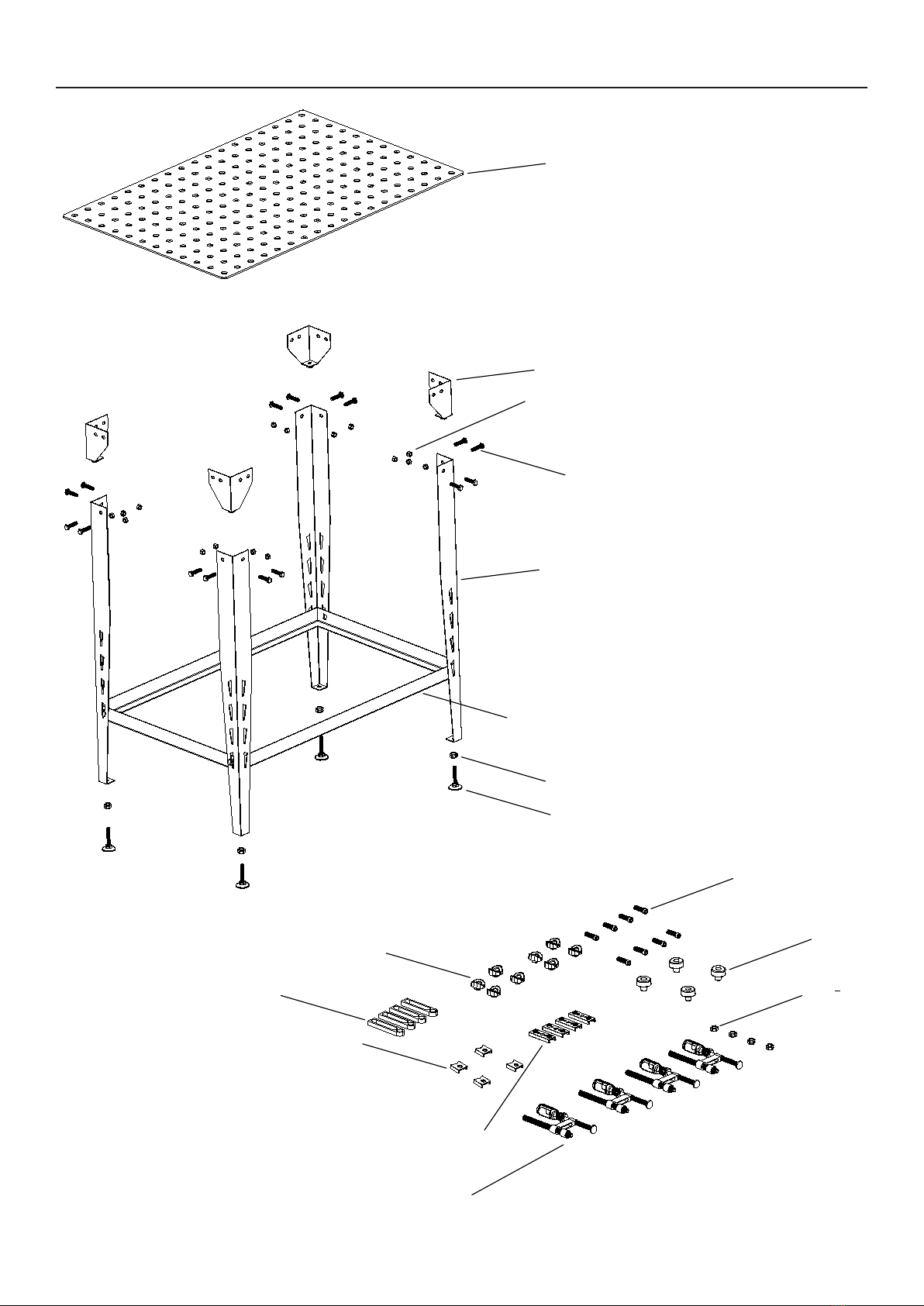
Assembly Diagram
1
2
3
4
5
8
6
7
9
10
11
12
13
14
15
16

Limited 90 Day Warranty
Harbor Freight Tools Co. makes every effort to assure that its products meet high quality and durability standards,
and warrants to the original purchaser that this product is free from defects in materials and workmanship for the
period of 90 days from the date of purchase. This warranty does not apply to damage due directly or indirectly,
to misuse, abuse, negligence or accidents, repairs or alterations outside our facilities, criminal activity, improper
installation, normal wear and tear, or to lack of maintenance. We shall in no event be liable for death, injuries
to persons or property, or for incidental, contingent, special or consequential damages arising from the use of
our product. Some states do not allow the exclusion or limitation of incidental or consequential damages, so the
above limitation of exclusion may not apply to you. THIS WARRANTY IS EXPRESSLY IN LIEU OF ALL OTHER
WARRANTIES, EXPRESS OR IMPLIED, INCLUDING THE WARRANTIES OF MERCHANTABILITY AND FITNESS.
To take advantage of this warranty, the product or part must be returned to us with transportation charges
prepaid. Proof of purchase date and an explanation of the complaint must accompany the merchandise.
If our inspection verifies the defect, we will either repair or replace the product at our election or we may
elect to refund the purchase price if we cannot readily and quickly provide you with a replacement. We will
return repaired products at our expense, but if we determine there is no defect, or that the defect resulted
from causes not within the scope of our warranty, then you must bear the cost of returning the product.
This warranty gives you specific legal rights and you may also have other rights which vary from state to state.
26677 Agoura Road • Calabasas, CA 91302 • 1-888-866-5797
Table of contents
Other Titanium Welding Accessories manuals


Popular Welding Accessories manuals by other brands


Magswitch Technology Inc.
Magswitch Technology Inc. Multi-Angle 400 Magvise Operation and instruction manual

Telwin
Telwin TW 9000 manual

Abicor Binzel
Abicor Binzel MF1-Rear operating instructions

Amada
Amada THIN-LINE 180 M Series Operation manual

Professional Tool Products
Professional Tool Products PWH4000 quick start guide

Abicor Binzel
Abicor Binzel SR 9 operating instructions


