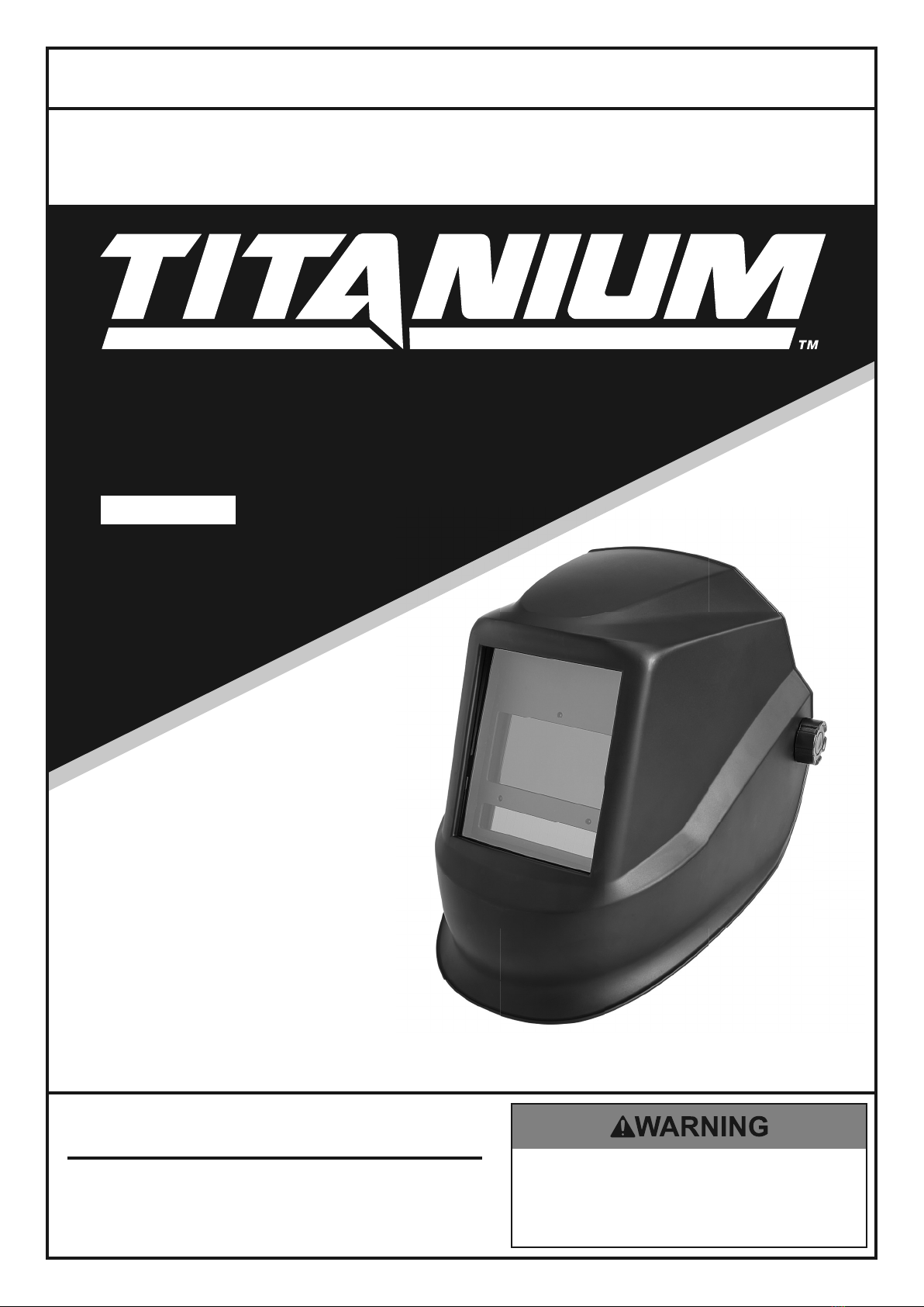
Titanium TI-TCWH7 Assembly instructions
!"#"$%&'(%)*+#"$*%,$-%.$$/-00)))1.,(+&(2(*"3.$14&5
65,"7%&'(%$*4.8"4,7%#'//&($%,$-%/(&9'4$#'//&($:.,(+&(2(*"3.$14&5
TI-TCWH7
58058
Owner’s Manual & Safety Instructions
Save This Manual Keep this manual for the safety warnings and precautions, assembly,
operating, inspection, maintenance and cleaning procedures. Write the product’s serial number in the
back of the manual near the assembly diagram (or month and year of purchase if product has no number).
Keep this manual and the receipt in a safe and dry place for future reference. 20l
When unpacking, make sure that the product is intact
and undamaged. If any parts are missing or broken,
please call 1-888-866-5797 as soon as possible.
Copyright© 2020 by Harbor Freight Tools®. All rights reserved.
No portion of this manual or any artwork contained herein may be reproduced in
any shape or form without the express written consent of Harbor Freight Tools.
Diagrams within this manual may not be drawn proportionally. Due to continuing
improvements, actual product may differ slightly from the product described herein.
Tools required for assembly an d se rv ic e may n ot b e in cl uded.
Read this material before using this product.
Failure to do so can result in serious injury.
SAVE THIS MANUAL.
Page 2 ;&(%$*4.8"4,7%<'*#$"&8#=%/7*,#*%4,77%>?@@@?@AA?BCDC1 Item 58058
EF;6GH IJ6KFGLIM NFLMG6MFMO6EJ6OL;LOFGLIME
G,+7*%&2%O&8$*8$#
Safety ......................................................... 2
Specifications ............................................. 4
Operation .................................................... 6
Maintenance and Servicing ........................ 9
Parts List and Diagram .............................. 11
Warranty .................................................... 12
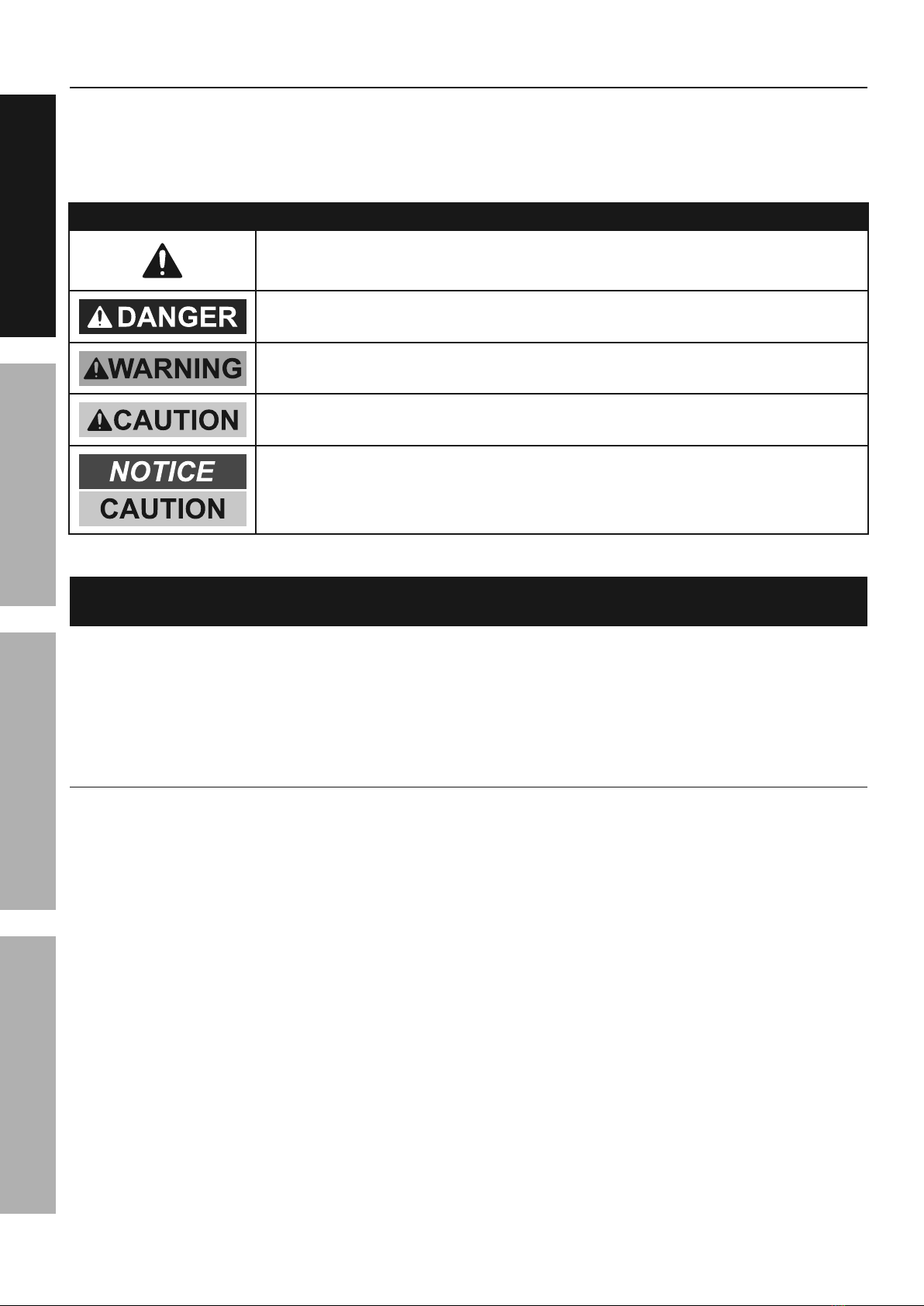
PFKMLMQ%EHNRISE%FMT%T6;LMLGLIME
This is the safety alert symbol. It is used to alert you to potential
personal injury hazards. Obey all safety messages that
follow this symbol to avoid possible injury or death.
Indicates a hazardous situation which, if not avoided,
will result in death or serious injury.
Indicates a hazardous situation which, if not avoided,
could result in death or serious injury.
Indicates a hazardous situation which, if not avoided,
could result in minor or moderate injury.
Addresses practices not related to personal injury.
LNJIKGFMG%EF;6GH%LM;IKNFGLIM
P.*8%'#"83%.*75*$=%+,#"4%#,2*$U%/(*4,'$"&8#%#.&'79%,7),U#%+*%2&77&)*9%$&%
(*9'4*%$.*%("#V%&2%/*(#&8,7%"8W'(U%,89%9,5,3*%$&%*<'"/5*8$1
G.*%),(8"83#=%4,'$"&8#=%,89%"8#$('4$"&8#%9"#4'##*9%"8%$."#%"8#$('4$"&8%5,8',7%4,88&$%4&X*(%,77%/&##"+7*%
4&89"$"&8#%,89%#"$',$"&8#%$.,$%5,U%&44'(1%%L$%5'#$%+*%'89*(#$&&9%+U%$.*%&/*(,$&(%$.,$%4&55&8%#*8#*%
,89%4,'$"&8%,(*%2,4$&(#%)."4.%4,88&$%+*%+'"7$%"8$&%$."#%/(&9'4$=%+'$%5'#$%+*%#'//7"*9%+U%$.*%&/*(,$&(1%
K*,9%,77%"8#$('4$"&8#%+*2&(*%'#"83%$."#%.*75*$Y%
1. T&%8&$%'#*%$.*%P*79"83%Z*75*$%"2%$.*%7*8#%"#%
4(,4V*9=%"2%$.*%7*8#%&(%#*8#&(#%,(*%9"($U=%&(%"2%
$.*%7*8#%&(%2(&8$%(*$,"8"83%2(,5*%"#%7&&#*1
2. [**/%)&(V%,(*,%47*,81 Cluttered
areas invite injuries.
3. I+#*(X*%)&(V%,(*,%4&89"$"&8#1 Do not use
welding helmets in damp or wet locations.
Do not expose to rain. Keep work area well
lit. Do not use auto-darkening helmets in the
presence of flammable gases or liquids.
4. [**/%4."79(*8%,),U1 Children must never
be allowed in the work area. Do not let them
handle this helmet. Dress properly. Do not
wear loose clothing or jewelry. Keep your hair,
clothing and gloves away from moving parts.
5. E$&(*%"97*%*<'"/5*8$1 When not in use,
helmets must be stored in a dry location
to inhibit rust. Always lock up helmets
and keep out of reach of children.
6. T(*##%/(&/*(7U1 Do not wear loose clothing
or jewelry as they can be caught in moving
parts. Protective gear is essential to protect
against welding rays, some examples are: a
leather welding apron, welding sleeves, jeans
without cuffs, work boots. Wear restrictive
hair covering to contain long hair.
7. \#*%+(*,$."83%,89%.*,("83%/(&$*4$"&81
Wear a NIOSH-approved respirator and
hearing protection when welding.
8. E$,U%,7*($1 Watch what you are doing, use
common sense. Do not weld when you are tired.
9. T&%8&$%)*79%"2%'89*(%$.*%"827'*84*%&2%
,74&.&7%&(%9('3#1 Read warning labels on
prescriptions to determine if your judgment
or reflexes are impaired while taking drugs.
If there is any doubt, do not weld.

Page 3;&(%$*4.8"4,7%<'*#$"&8#=%/7*,#*%4,77%>?@@@?@AA?BCDC1Item 58058
EF;6GHIJ6KFGLIMNFLMG6MFMO6 EJ6OL;LOFGLIME
PFKMLMQ
LMZFSFGLIM%ZF]FKT-%
P*79"83%,89%J7,#5,%O'$$"83%J(&9'4*%
GI^LO%;\N6E1
Exposure to welding or cutting exhaust
fumes can increase the risk of developing
certain cancers, such as cancer of the
larynx and lung cancer. Also, some
diseases that may be linked to exposure
to welding or plasma cutting exhaust
fumes are:
• Early onset of Parkinson’s Disease
• Heart disease • Ulcers
• Damage to the reproductive organs
• Inflammation of the small intestine or
stomach • Kidney damage
• Respiratory diseases such as
emphysema, bronchitis, or pneumonia
Use natural or forced air ventilation and
wear a respirator approved by NIOSH to
protect against the fumes produced to
reduce the risk of developing the above
illnesses.
10. O.*4V%2&(%9,5,3*9%/,($#1%%Before using any
helmet, any part that appears damaged should be
carefully checked to determine that it will operate
properly and perform its intended function. Check
for alignment and binding of moving parts; any
broken parts or mounting fixtures; and any other
condition that may affect proper operation. Any
part that is damaged should be properly repaired
or replaced by a qualified technician. Do not use
the helmet if any switch does not operate properly.
11. K*/7,4*5*8$%/,($#%,89%,44*##&("*#1 When
servicing, use only identical replacement parts.
Use of any other parts can render helmet ineffective,
possibly causing eye damage, and will void the
warranty. Only use accessories intended for
use with this helmet. Approved accessories
are available from Harbor Freight Tools.
12. N,"8$*8,84*1 For your safety, service
and maintenance should be performed
regularly only by a qualified technician.
13. G."#%.*75*$%/(&X"9*#%/(&$*4$"&8%2&(%"8$*89*9%
/'(/&#*#%&87U1 There are certain applications
for which this helmet was designed. Do not
modify this helmet and do not use this helmet
for a purpose for which it was not intended:
a. G.*%P*79"83%Z*75*$ is not
suitable for laser welding.
b. G.*%P*79"83%Z*75*$ will not protect
against severe impact hazards.
c. G.*%P*79"83%Z*75*$ will not protect against
explosive devices or corrosive liquids.
14. \#*%&87U%,$%$*5/*(,$'(*#%)"$."8%$.*%&/*(,$"83%
(,83*%2&(%U&'(%5&9*7%,#%#$,$*9%&8%$.*%
#/*4"2"4,$"&8#%4.,($%"8%$."#%5,8',71
15. Maintain the helmet and lens correctly
to help ensure reliable protection:
a. Clean filter’s surfaces regularly. Keep sensors
and solar cells clean using a clean lint-
free tissue/cloth. Do not use any solvents
on filter’s screen or helmet components.
Protect filter from liquid and dirt contact.
Do not immerse the filter in water.
b. Should the Auto-Darkening Welding Helmet
not darken upon striking an arc, stop
welding immediately and have the helmet
checked by a qualified service technician.
c. Regularly replace the Front Lens Cover
if it becomes cracked, scratched,
pitted, or otherwise damaged.
d. Do not make any modifications to either the
Auto-Darkening Filter or the rest of the helmet,
other than those specified in this manual. Do
not use any replacement parts other than
those specified in this manual. Unauthorized
modifications and replacement parts will
void the warranty and expose the user to
the risk of personal injury. Do not open or
tamper with the Auto-Darkening Filter.
16. Do not place the Welding Helmet’s Auto-
Darkening Filter on a hot surface.
17. E6!6K6%J6KEIMFS%LM_\KH%,890&(%
RSLMTM6EE%5,U%&44'(%"2%$.*%'#*(%2,"7#%$&%
2&77&)%$.*%,2&(*5*8$"&8*9%),(8"83#%,890&(%
2,"7#%$&%2&77&)%$.*%&/*(,$"&8%"8#$('4$"&8#1
18. Maintain labels and nameplates on the tool.
These carry important safety information.
If unreadable or missing, contact
Harbor Freight Tools for a replacement.
%EF!6%GZ6E6%LMEGK\OGLIME1
Page 4 ;&(%$*4.8"4,7%<'*#$"&8#=%/7*,#*%4,77%>?@@@?@AA?BCDC1 Item 58058
EF;6GH IJ6KFGLIM NFLMG6MFMO6EJ6OL;LOFGLIME
E/*4"2"4,$"&8#
Description Auto-Darkening Welding Helmet
Power Source Solar powered cell with battery assistance
(replaceable 3V CR2450 lithium battery)
Operating Temperature 14° to 149° F
Resting Shade Shade # 3
Shade Range 5 to 9 – 9 to 13 variable
UV/IR Protection Up to DIN 15 at all times
Lens Type ANSI Z87.1-2020 compliant
Viewing Area 1.84" L x 3.81" W (7.1 sq. in.)
Welding Protection
Types
For all arc welding processes including MIG/Flux welding, stick welding,
TIG welding (2+ amps), plasma arc welding/cutting, Oxyacetylene
welding/cutting and air carbon cutting. Not for Laser Welding.
Lens Switching Speed (Clear to Dark) 1/25,000 second (0.04 ms)
Delay Control Controls dark-to-light state from 0.1 to 0.9 seconds
Sensitivity Adjustment Adjustable for ambient lighting (including
sun light) and other welding arcs
Grinding Mode Transforms helmet to grinding shield without shade flickering
Power ON / OFF Fully Automatic
Shell Material Nylon PA 66
Weight 20.6 ounces
Features Ratcheting headband with padded sweatband, 3 arc sensors,
Shade Control, Time Delay Control, Sensitivity Control.

Page 5;&(%$*4.8"4,7%<'*#$"&8#=%/7*,#*%4,77%>?@@@?@AA?BCDC1Item 58058
EF;6GHIJ6KFGLIMNFLMG6MFMO6 EJ6OL;LOFGLIME
E.,9*%Q'"9*%O.,($
Guide for Shade Numbers
Shade numbers are given as a guide only and may be varied to suit individual needs.
JKIO6EE 6S6OGKIT6%EL]6 FKO%O\KK6MG%
`F5/*(*#a
NLMLN\N%
JKIG6OGL!6%
EZFT6
E\QQ6EG6T,%
EZFT6%MI1%
`O&52&($a
Shielded Metal Arc
Welding (SMAW)
Less than 3/32" (2.4 mm) Less than 60 7 —
3/32 – 5/32" (2.4 – 4.0 mm) 60 –160 8 10
5/32 – 1/4" (4.0 – 6.4 mm) 160 – 250 10 12
More than 1/4" (6.4 mm) 250 – 550 11 14
Gas Metal Arc Welding
(GMAW) and Flux-Cored
Arc Welding (FCAW)
Less than 60 7 —
60 –160 10 11
160 – 250 10 12
250 – 550 10 14
Gas Tungsten Arc
Welding (GTAW)
Less than 50 8 10
50 –150 8 12
150 – 500 10 14
Air Carbon Arc
Cutting (CAC-A)
SLQZG- Less than 500 10 12
Z6F!H- 500 –1000 11 14
Plasma Arc Welding (PAW)
Less than 20 6 6 to 8
20 –100 8 10
100 – 400 10 12
400 – 800 11 14
Plasma Arc Cutting (PAC)
Less than 20 4 4
20 – 40 5 5
40 – 60 6 6
60 – 80 8 8
80 – 300 8 9
300 – 400 9 12
400 – 800 10 14
Torch Brazing (TB) — — 3 or 4
Torch Soldering (TS) — — 2
Carbon Arc Welding (CAW) — — 14
JSFG6%GZLO[M6EE
JKIO6EE LM NN E\QQ6EG6T%EZFT6%MI1,%`O&52&($a
Oxyfuel Gas Welding (OFW)
Light
Medium
Heavy
Under 1/8"
1/8 to 1/2"
Over 1/2"
Under 3 mm
3 to 13 mm
Over 13 mm
4 or 5
5 or 6
6 or 8
Oxygen Cutting (OC)
Light
Medium
Heavy
Under 1"
1 to 6"
Over 6"
Under 25 mm
25 to 150 mm
Over 150 mm
3 or 4
4 or 5
5 or 6
a As a rule of thumb, start with a shade that is too dark to see the weld zone. Then go to a lighter shade which
gives sufficient view of the weld zone without going below the minimum. In oxyfuel gas welding, cutting, or
brazing where the torch and/or the flux produces a high yellow light, it is desirable to use a filter lens that
absorbs the yellow or sodium line of the visible light spectrum.
Data from ANSI Z49.1 : 2012
Page 6 ;&(%$*4.8"4,7%<'*#$"&8#=%/7*,#*%4,77%>?@@@?@AA?BCDC1 Item 58058
EF;6GH IJ6KFGLIM NFLMG6MFMO6EJ6OL;LOFGLIME
I/*(,$"83%L8#$('4$"&8#
% K*,9%$.*%6MGLK6%LNJIKGFMG%EF;6GH%LM;IKNFGLIM%#*4$"&8%,$%$.*%+*3"88"83%&2%$."#%
5,8',7%"847'9"83%,77%$*b$%'89*(%#'+.*,9"83#%$.*(*"8%+*2&(*%#*$%'/%&(%'#*%&2%$."#%/(&9'4$1
;'84$"&8
The Auto-Darkening Welding Helmet is designed to protect the eyes and face from sparks, splatter, and
harmful radiation under normal welding conditions. The Auto-Darkening Filter automatically changes from
a clear state to a dark state when an arc is struck, and it returns to the clear state when welding stops.
E&7,(%O*77#
This Welding Helmet utilizes high performance solar cells as its power supply, and has a replaceable 3V CR2450
lithium battery as power backup. Refer to Maintenance section for battery replacement information.
E.,9*#
User-selectable variable shades from 5 to 9 and 9 to 13 are adjusted with the Set
Switch, Set Switch, and Range Switch. This product is in full conformity with related
DIN, ISO, EN379 safety standards and ANSI Z87.1-2020 standard.
;"7$*(#
The ultra high performance of UV and IR Auto-Darkening filters provides the user’s eyes
and face with full protection against UV and IR radiation during the entire welding process,
even in clear state. The UV/IR protection level is up to shade 15 at all times.
N,38"2U"83%O.*,$*(%S*8#
To attach a magnifying cheater lens (sold separately) to the inside of the helmet, slide the cheater lens
into place underneath the tabs located on the lower right and left sides of the Lens Retaining Frame.
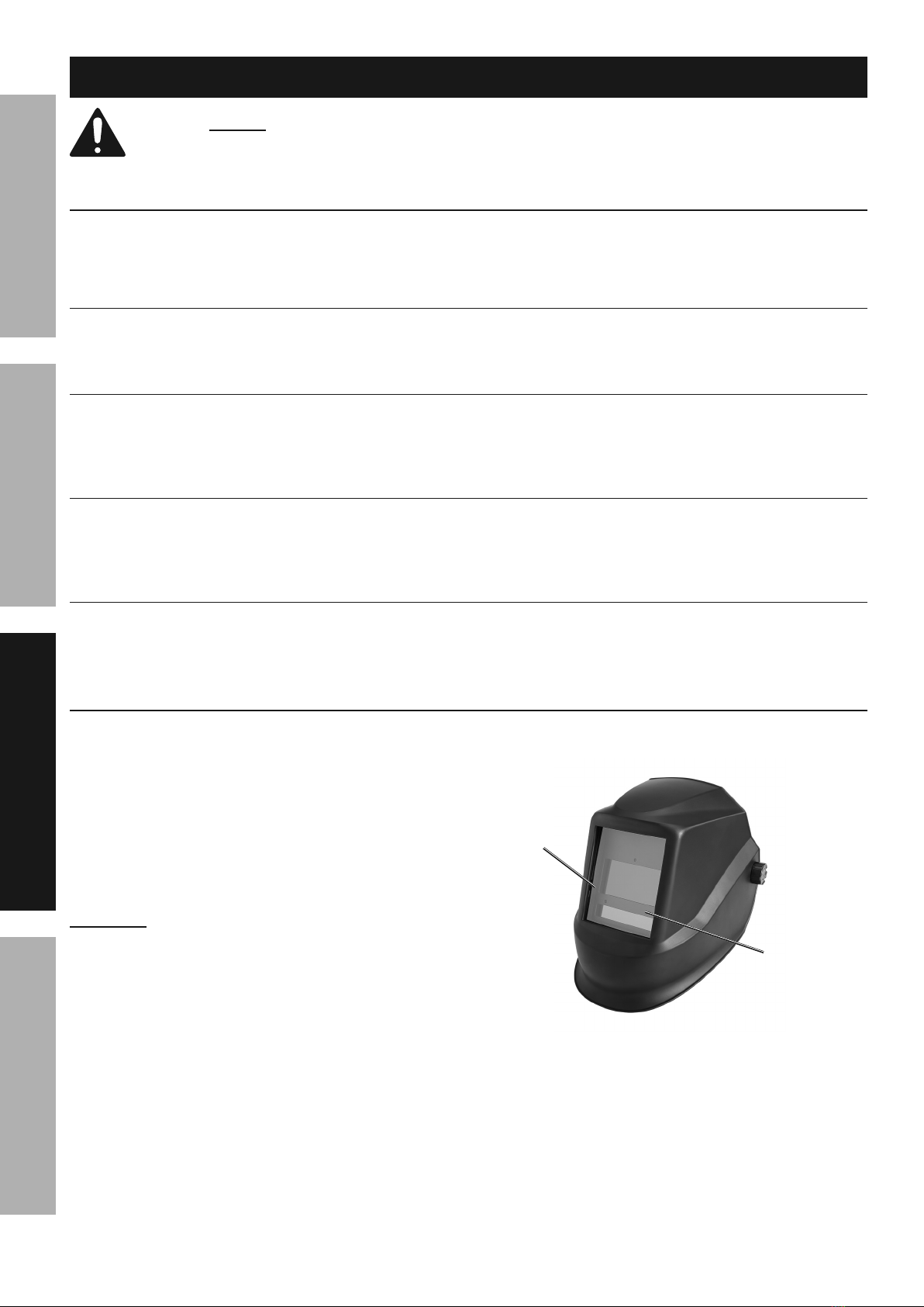
R*2&(*%P*79"83
The Auto-Darkening Welding Helmet comes ready
for use. Prior to first use, remove the protective film
from both sides of the Front Lens Cover and Inside
Lens Cover (if not already done). Check the Front
Lens Cover to make sure that it is clean, and that
no dirt is covering the four sensors on the front of
the Auto Darkening Filter Cartridge. Also check the
Inside Lens Cover and the Lens Retaining Frame,
and make sure that they are secured in place.
L5/&($,8$- Make sure battery is properly
installed before first use. Helmet is shipped
with one CR2450 Lithium Battery.
Adjust the position of the headband, select the correct
shade number for the welding application, and test
the helmet for proper operation as described below.
Inspect all operating parts before each use for signs
of wear or damage. Any scratched, cracked, or
pitted parts should be replaced immediately before
using again to avoid severe personal injury.
F'$&%
T,(V*8"83%
;"7$*(%
O,($("93*
;(&8$%
S*8#%
O&X*(
;"3'(*%F-%%Z*75*$

Page 7;&(%$*4.8"4,7%<'*#$"&8#=%/7*,#*%4,77%>?@@@?@AA?BCDC1Item 58058
EF;6GHIJ6KFGLIMNFLMG6MFMO6 EJ6OL;LOFGLIME
O&8$(&7#
Option
Selection
Mode
Selection
Level
Selection
Display
Mode
Indicator
;"3'(*%R-%%O&8$(&7#
N&9*%E*7*4$"&8%,89%E.,9*%M'5+*(
1. Use Set Switch to choose the Shade option.
2. Press Mode Switch to choose between
Shade 5-9 or Shade 9-13. Selections will
be shown on the display screen.
3. Using the Shade Guide Chart on page 5,
select the shade range required using the Mode
switch and then adjust the Shade Level upwards
or downwards by using the Range switch.
M&$*- If a selection of shades are recommended
for your application, try the darkest setting first.
4. To switch between Cut and Grind
mode, press the Mode switch.
M&$*- To switch modes, you must not be in “Set” options.
5. The light next to “Grind” or “Cut” will
indicate the mode after switching.
OF\GLIMY F2$*(%'#"83%$.*%Q("89%N&9*%#*$%$.*%Z*75*$%
$&%$.*%/(&/*(%#.,9*%#*$$"83%+*2&(*%)*79"83%,3,"81%
6. The shade number can be set from 5 to 9
(cutting) or from 5 to 9 and 9 to 13 (welding)
depending on the shade range selected.
G"5*%T*7,U%,89%E*8#"$"X"$U
1. At the moment the welding operation is started,
the filter screen automatically changes from
clear to dark. The Delay function can vary
the amount of time it takes the filter to return
to a clear state after welding stops. Press
Set Switch to select the Delay option.
2. Use the Range Switch to shorten or lengthen the
delay time. The shortest delay time is 0.1 seconds
(set to 1 using Range Switch). The longest delay
time is 0.9 seconds (set to 5 using Range Switch).
3. The sensitivity setting changes the amount of
light needed to make the filter react. Press the
Set Switch to choose the Sensitivity option.
4. Use the Range switch to raise or lower the
sensitivity (five stages of sensitivity are
available).1 indicates the lowest sensitivity,
and 5 indicates the highest sensitivity.
Page 8 ;&(%$*4.8"4,7%<'*#$"&8#=%/7*,#*%4,77%>?@@@?@AA?BCDC1 Item 58058
EF;6GH IJ6KFGLIM NFLMG6MFMO6EJ6OL;LOFGLIME
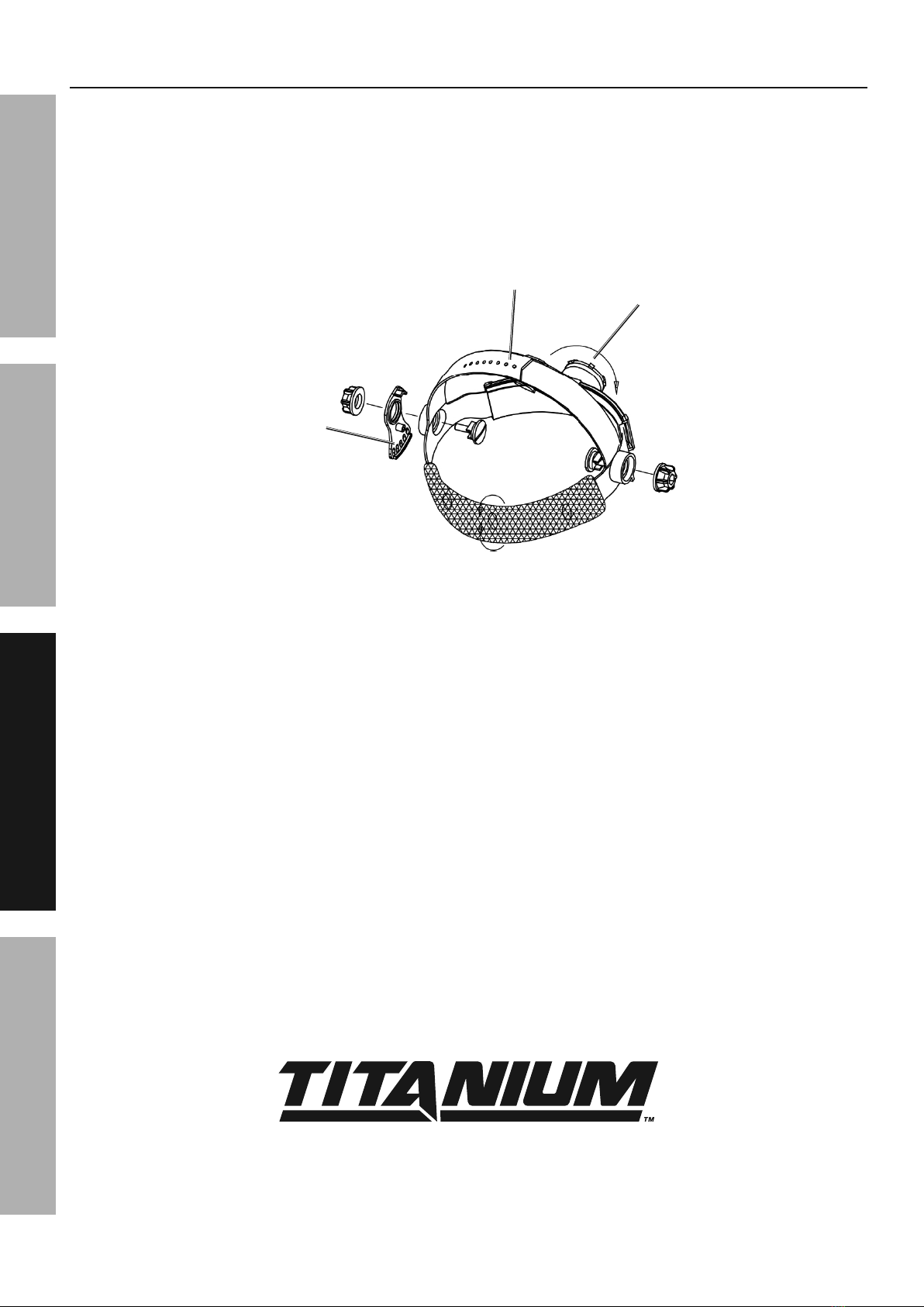
F9W'#$"83%Z*,9+,89
Adjust the Headband so that the Helmet is seated
securely on your head as low as possible and close
to your face using the following procedure:
1. Adjust Helmet Height by tightening or loosening the
Top Straps until the Helmet fits snug on your head.
2. Adjust the Head Size by using the Head Size
Adjustment Knob. Size should be adjusted so
that the Front Lens Cover is aligned with your
eyes and the Helmet fits firmly on your head.
3. Use the Segmental Positioning Mechanism
to adjust the position of the Protection
Plate for optimal viewing angles.
Head Size
Adjustment
Top Straps
Segmental
Positioning
Mechanism
;"3'(*%O-%%Z*,93*,(%E*$'/

Page 9;&(%$*4.8"4,7%<'*#$"&8#=%/7*,#*%4,77%>?@@@?@AA?BCDC1Item 58058
EF;6GHIJ6KFGLIMNFLMG6MFMO6 EJ6OL;LOFGLIME
N,"8$*8,84*
GI%JK6!6MG%E6KLI\E%LM_\KH%;KIN%GIIS%;FLS\K6-%%T&%8&$%'#*%9,5,3*9%*<'"/5*8$1%%
L2%9,5,3*%&(%,+8&(5,7%&/*(,$"&8%&44'(#=%.,X*%$.*%/(&+7*5%4&((*4$*9%+*2&(*%2'($.*(%'#*1
R6;IK6%6FOZ%\E6=%"8#/*4$%$.*%3*8*(,7%4&89"$"&8%&2%$.*%$&&71%%O.*4V%2&(%7&&#*%
.,(9),(*=%5"#,7"385*8$%&(%+"89"83%&2%5&X"83%/,($#=%4(,4V*9%&(%+(&V*8%/,($#=%9,5,3*9%
*7*4$("4,7%)"("83=%,89%,8U%&$.*(%4&89"$"&8%$.,$%5,U%,22*4$%"$#%#,2*%&/*(,$"&81
M&$*- Replace the Lens Cover(s) if they are cracked, scratched, soiled, pitted or damaged in any way. For
additional information regarding the parts listed in the following pages, refer to Parts List and Diagram on page 11.
I'$*(%S*8#%K*/7,4*5*8$%
1. Remove the Lens Frame from the Helmet Shell.
Once the Lens Frame is removed, remove
the Outer Lens from the Helmet Shell.
2. Remove any protective film from both
sides of the new Lens Cover.
3. Install new Front Lens Cover into Gasket and
assemble Lens, Gasket, and Lens Holder into
Shell the same way they were removed.
MIGLO6- Front lens must be in place during
welding. Weld spatter will permanently damage
Auto-Darkening Filter and voids warranty.
L8#"9*%S*8#%O&X*(%K*/7,4*5*8$
1. Remove the old Inside Lens Cover by
pulling it up at the finger notch.
2. Remove any protective film from both
sides of the new Lens Cover.
3. Line up the new Inside Lens Cover with the flanges
at the sides of the lens and snap it into place.
L8#"9*%
S*8#%
O&X*(%
;"83*(%M&$4.
;"3'(*%T-%%L8#"9*%S*8#%J,8*7%E*$'/
R,$$*(U%
Z&'#"83

Page 10 ;&(%$*4.8"4,7%<'*#$"&8#=%/7*,#*%4,77%>?@@@?@AA?BCDC1 Item 58058
EF;6GH IJ6KFGLIM NFLMG6MFMO6EJ6OL;LOFGLIME
;"7$*(%S*8#%K*/7,4*5*8$
1. Remove the Lens Frame from the Helmet Shell.
2. Remove the Auto-Darkening Filter
from the Lens Frame.
PFKMLMQY%%GI%JK6!6MG%E6KLI\E%LM_\KH%
FMT%RSLMTM6EE-%
K*/7,4*%$.*%2"7$*(%7*8#%IMSH%)"$.%,8%*b,4$%
(*/7,4*5*8$1%%I$.*(%7*8#*#%5,U%8&$%/(&$*4$%
/(&/*(7U%2(&5%)*79"83%7"3.$=%&(%5,U%8&$%2"$%.*75*$%
47&#*7U%*8&'3.%$&%+7&4V%,77%7"3.$%,$%$.*%*93*#1
3. Remove any protective film from
both sides of the new Lens.
4. Install new Filter Lens into the Lens Holder
and replace Lens Holder into Shell.
R,$$*(U%L8#$,77,$"&8%&(%K*/7,4*5*8$
There is a battery indicator in the top
left corner of the Display Screen
To install Battery:
1. Remove the Automatic Filter from the Lens Holder.
2. Slide the Battery Housing out of the
Auto-Darkening Filter. Remove the used
battery (if applicable). See Figure D
M&$*- All used batteries must be properly disposed of.
3. Place a new CR2450 Lithium Battery inside
the Battery Holder and put the Battery Holder
back into the Auto-Darkening Filter. Make
sure the new Battery is installed correctly.
4. Replace the Auto-Darkening Filter into the Lens
Holder and replace Lens Holder into Shell.
O&55&8%J(&+7*5#%,89%K*5*9"*#
1. L((*3'7,(%T,(V*8"83%I(%T"55"83
a. Headband has been set unevenly on
both sides of helmet (unequal distances
from the eyes to filter’s lens).
b. Reset Headband to reduce difference
in distances to filter, if necessary.
2. F'$&?T,(V*8"83%;"7$*(%T&*#%
M&$%T,(V*8%I(%;7"4V*(#
a. Front Lens Cover is soiled or
damaged (change the cover).
b. Sensors are soiled (clean surface of the sensors).
c. Welding current is too low (adjust sensitivity).
3. E7&)%K*#/&8#*
Operating temperature is too low (do not
use at temperatures below 14° F).
4. J&&(%!"#"&8
a. Front/Inside Lens Cover and/
or Filter soiled (change it).
b. Insufficient ambient light.
c. Shade number is incorrectly set
(reset shade number).
5. P*79"83%Z*75*$%E7"/#
Headband is not adjusted properly
(adjust to fit head snugly).
E$&/%'#"83%$.*%Z*75*$%"55*9",$*7U%"2%,8U%
&2%$.*#*%/(&+7*5#%4,88&$%+*%4&((*4$*91

Page 11;&(%$*4.8"4,7%<'*#$"&8#=%/7*,#*%4,77%>?@@@?@AA?BCDC1Item 58058
EF;6GHIJ6KFGLIMNFLMG6MFMO6 EJ6OL;LOFGLIME
J,($#%S"#$%,89%T",3(,5
JS6FE6%K6FT%GZ6%;ISSIPLMQ%OFK6;\SSH
THE MANUFACTURER AND/OR DISTRIBUTOR HAS PROVIDED THE PARTS DIAGRAM IN THIS MANUAL
AS A REFERENCE TOOL ONLY. NEITHER THE MANUFACTURER NOR DISTRIBUTOR MAKES ANY
REPRESENTATION OR WARRANTY OF ANY KIND TO THE BUYER THAT HE OR SHE IS QUALIFIED TO
MAKE ANY REPAIRS TO THE PRODUCT OR THAT HE OR SHE IS QUALIFIED TO REPLACE ANY PARTS
OF THE PRODUCT. IN FACT, THE MANUFACTURER AND/OR DISTRIBUTOR EXPRESSLY STATES
THAT ALL REPAIRS AND PARTS REPLACEMENTS SHOULD BE UNDERTAKEN BY CERTIFIED AND
LICENSED TECHNICIANS AND NOT BY THE BUYER. THE BUYER ASSUMES ALL RISK AND LIABILITY
ARISING OUT OF HIS OR HER REPAIRS TO THE ORIGINAL PRODUCT OR REPLACEMENT PARTS
THERETO, OR ARISING OUT OF HIS OR HER INSTALLATION OF REPLACEMENT PARTS THERETO.
J,($#%S"#$%,89%F##*5+7U%T",3(,5
J,($ T*#4("/$"&8 c$U
1 Helmet Shell 1
2 Outer Protection Lens 1
3 Auto-Darkening Filter Frame 1
4 Auto-Darkening Filter 1
5 Inner Protection Lens 1
6 Headgear 1
K*4&(9%J(&9'4$d#%E*(",7%M'5+*(%Z*(*-%
M&$*- If product has no serial number, record month and year of purchase instead.
M&$*- Some parts are listed and shown for illustration purposes only, and are not available
individually as replacement parts. Specify UPC 193175431325 when ordering parts.
:
DRAWING NO.
Revision Description Revision Date
APPROVED
TECHNOLOGY
CHECKED
DRAWN
DATESIGNED BYCHANGE NO.
QUANTITY
MARK
±2°
TITLE:
MATERIAL:
SURFACE TREATMENT:
±0.20 ±0.30
±0.15
±0.10
±0.05 ±0.50
0.5-6 6-30 30-120 120-400 400-1000 1000-2000
DRAWING NO.
REV SCALE UNITS SHEET
A/0 1:1 mm 1/1
EXPLODE DRAWING
WF3363386 00000
NO. Description
1Helmet shell
2Outer protection lens
3 ADF cradle
4ADF
5Inner protection lens
6Headgear

S"5"$*9%De%T,U%P,((,8$U
Harbor Freight Tools Co. makes every effort to assure that its products meet high quality and durability standards,
and warrants to the original purchaser that this product is free from defects in materials and workmanship for the
period of 90 days from the date of purchase. This warranty does not apply to damage due directly or indirectly,
to misuse, abuse, negligence or accidents, repairs or alterations outside our facilities, criminal activity, improper
installation, normal wear and tear, or to lack of maintenance. We shall in no event be liable for death, injuries
to persons or property, or for incidental, contingent, special or consequential damages arising from the use of
our product. Some states do not allow the exclusion or limitation of incidental or consequential damages, so the
above limitation of exclusion may not apply to you. THIS WARRANTY IS EXPRESSLY IN LIEU OF ALL OTHER
WARRANTIES, EXPRESS OR IMPLIED, INCLUDING THE WARRANTIES OF MERCHANTABILITY AND FITNESS.
To take advantage of this warranty, the product or part must be returned to us with transportation charges
prepaid. Proof of purchase date and an explanation of the complaint must accompany the merchandise.
If our inspection verifies the defect, we will either repair or replace the product at our election or we may
elect to refund the purchase price if we cannot readily and quickly provide you with a replacement. We will
return repaired products at our expense, but if we determine there is no defect, or that the defect resulted
from causes not within the scope of our warranty, then you must bear the cost of returning the product.
This warranty gives you specific legal rights and you may also have other rights which vary from state to state.
fABg>%F3&'(,%K&,9%%h%%O,7,+,#,#=%OF%D>ief%%h%%>?@@@?@AA?BCDC
Other manuals for TI-TCWH7
1
This manual suits for next models
1
Table of contents
Other Titanium Welding Accessories manuals


