Titon HRV10 Q Plus User manual

ventilation systems
EN
HRV10 Q Plus
TP440HMB
HRV10M Q Plus
TP441HMB
Heat Recovery Ventilation Unit
auralite®
TP518
LED Status IndicatorProduct Manual

Warnings, Safety information and
Guidance
Important Information
Important: read these instructions fully before the
installation of this appliance
1. Installation of the appliance and accessories must be carried
out by a qualied and suitable competent person and be car-
ried out in clean, dry conditions where dust and humidity are
at minimal levels.
2. All wiring must conform to current I.E.E. Wiring Regulations
and all applicable standards and Building Regulations.
3. Inspect the appliance and electrical supply cord. If the supply
cord is damaged, it must be replaced by the manufacturer,
their service agent or similarly qualied persons in order to
avoid a hazard.
4. The unit is supplied with a mains rated 3 core exible cord
(PVC sheathed, brown, blue and green/yellow 0.75mm²).
5. The appliance must be connected to a local double pole iso-
lation switch with a contact separation of at least 3mm.
6. The appliance must be earthed.
7. Suitable for 230V ~ 50/60Hz single phase with a fuse rating
of 3A.
8. auralite®, control & communication cable access is via the t-
ted cable gland(s) which are suitable for Ø3- 6mm cable.
9. auralite® control & communication cable - Unshielded 4 Core
18-24AWG Stranded, Tinned Copper.
2

10. Control & communication cables should not be placed within
50mm or on the same metal cable tray as any 230V lighting
or power cables.
11. Ensure all cable glands are fully tightened.
12. The unit must be stored in a clean and dry environment. Do
not install the appliance in areas where the following may be
present or occur;
• Excessive oil or a grease laden atmosphere,
• Corrosive or ammable gases, liquids or vapours,
• Ambient temperatures above 40°C or below -5°C,
• Humidity levels above 90% or is a wet environment.
13. The appliance is not suitable for installation to the exterior of
the dwelling.
14. This appliance can be used by children aged from 8 years and
above and persons with reduced physical, sensory or mental
capabilities or lack of experience and knowledge if they have
been given supervision or instruction concerning use of the
appliance in a safe way and understand the hazards involved.
15. Children should be supervised to ensure that they do not
play with the appliance.
16. Ensure that external grilles are located away from any ue
outlet, in accordance with relevant Building Regulations.
17. The unit must not be connected to a tumble dryer.
18. The unit must not be connected to a cooker hood.
19. Precautions must be taken to avoid the back-ow of gases
into the room from an open ue appliance.
20. Ensure all ducting, condensate drain and associated pipe
work is free from debris and blockages before switching on
the unit.
3

Contents
Warnings, Safety information and Guidance
Important Information . . . . . . . . . . . . . . . . . . . . . . . . 2
Product Overview
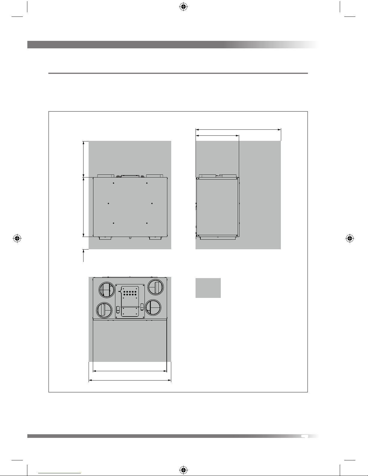
Dimensions HRV10 Q Plus. . . . . . . . . . . . . . . . . .6
Dimensions HRV10M Q Plus . . . . . . . . . . . . . . . .7
Product Features . . . . . . . . . . . . . . . . . . . . . . . . . . . . . 8
Controls & Features . . . . . . . . . . . . . . . . . . . . . . . . . . . 9
auralite® . . . . . . . . . . . . . . . . . . . . . . . . . . . . . . . 9
Auto Setback Speed. . . . . . . . . . . . . . . . . . . . .10
Continuous Speed . . . . . . . . . . . . . . . . . . . . . .10
Boost Speed with Overrun Timer . . . . . . . . . .10
auralite® Boost Alert . . . . . . . . . . . . . . . . . . . .10
Summer Bypass . . . . . . . . . . . . . . . . . . . . . . . .11
SUMMERboost® . . . . . . . . . . . . . . . . . . . . . . . .11
Automatic Frost Protection. . . . . . . . . . . . . . .12
Integrated Humidity Sensor. . . . . . . . . . . . . .12
Packaging Contents. . . . . . . . . . . . . . . . . . . . . . . . . .12
Installation
Fixing . . . . . . . . . . . . . . . . . . . . . . . . . . . . . . . . . . . . .14
Condensate Drain . . . . . . . . . . . . . . . . . . . . . . . . . . .17
Fitting . . . . . . . . . . . . . . . . . . . . . . . . . . . . . . . .18
Ducting Connections. . . . . . . . . . . . . . . . . . . . . . . . .19
Wiring Connections Access. . . . . . . . . . . . . . . . . . . .20
auralite Wiring Diagrams . . . . . . . . . . . . . . . .21
Wiring Diagrams . . . . . . . . . . . . . . . . . . . . . . .22
Wiring Diagrams . . . . . . . . . . . . . . . . . . . . . . .23
Wiring Diagrams . . . . . . . . . . . . . . . . . . . . . . .24
Wiring Diagrams . . . . . . . . . . . . . . . . . . . . . . .25
Commissioning
Controls. . . . . . . . . . . . . . . . . . . . . . . . . . . . . . . . . . . .26
Control Parameters . . . . . . . . . . . . . . . . . . . . .26
Continuous Supply & Extract Speeds. . . . . . .27
Boost Supply & Extract Speeds . . . . . . . . . . .27
Boost Overrun. . . . . . . . . . . . . . . . . . . . . . . . . .28
Humidity Sensor . . . . . . . . . . . . . . . . . . . . . . .28
Controller Reset . . . . . . . . . . . . . . . . . . . . . . . .29
Hardware Reset . . . . . . . . . . . . . . . . . . . . . . . .29
Maintenance
Routine Maintenance . . . . . . . . . . . . . . . . . . . . . . . .30
HRV 10 Q Plus Front Cover Removal . . . . . . .30
HRV 10M Q Plus Front Cover Removal. . . . . .31
Cleaning Interior . . . . . . . . . . . . . . . . . . . . . . .31
Cleaning Exterior . . . . . . . . . . . . . . . . . . . . . . .31
Filter Replacement. . . . . . . . . . . . . . . . . . . . . .32
auralite® Filter Notication Reset . . . . . . . . .33
Service Record . . . . . . . . . . . . . . . . . . . . . . . . . . . . . .34
Service Record . . . . . . . . . . . . . . . . . . . . . . . . . . . . . .35
When this document is
viewed as a PDF the headings
& sub headings on this page
are hyperlinks to the content.
Additionally the page numbers in this
document are hyperlinks back to this
contents page.
4

5

Product Overview
Dimensions HRV10 Q Plus
This diagram details the overall size of the unit and the additional space required
around the unit to allow for commissioning and future servicing and maintenance.
Service Void
484
920
663 400100
890
790
DO NOT
‘BOX IN’
UNIT
All dimensions in millimetres
6

Dimensions HRV10M Q Plus
This diagram details the overall size of the unit and the additional space required
around the unit to allow for commissioning and future servicing and maintenance.
All dimensions in millimetres
920
DO NOT
‘BOX IN’
UNIT
Service Void
470
800
900
100 400
675
7

Product Features
The table below lists the models covered by this Product Manual. To nd out what
features your Titon HRV Q Plus has refer to the part number. The part number can
be found on the serial number label xed to the top and front of the unit.
Model
Part
Number
auralite® Connection
Internal Humdity Sensor
Auto Setback Speed
Continuous Speed
Boost Speed with Overrun Timer
SUMMERboost®
Summer Bypass
Ø150mm Ducting
Independent Adjustment of Fans
Step-less Fan Speed Adjustment
Automatic Frost Protection
HRV10 Q Plus TP440HMB
HRV10M Q Plus TP441HMB
GB Patent Nos.
GB2491516, GB2471406
8

Controls & Features
The HRV Q Plus units are controllable by various volt free switches and sensors.
The following describes the controls and features of the HRV Q Plus units and how
they are controlled. Refer to the table opposite. Ensure all controls are adequately
labelled, indicating their function clearly.
auralite®
auralite® is available separately as an optional add-on. auralite® is a low voltage
hard wired remote LED ventilation system status indicator, designed to t a
standard UK patress or recessed backbox. The indicator has six LEDs which display:-
Normal Solid light - Unit is running at Continuous Speed.
Flashing light - Unit is running at Setback Speed.
Frost Unit is in Automatic Frost Protection mode.
Filter Filters require change.
Boost Solid light - Unit is running at Boost Speed.
Flashing light Boost Alert is active.
Summer Unit is in Summer bypass.
Fault Unit has a fault - Contact the installer.
Ventilation
System
auralite® Indicator Panel
9

Auto Setback Speed
Setback Speed is used to reduce ventilation rates. Setback Speed is automatically
set at the mid point between minimum possible Continuous Speed and the
selected Continuous Speed. The Setback Speed can be enabled by connection of a
volt free one-way switch, or combined with the Boost Speed with the 3 position
switch TP 508.
Continuous Speed
Continuous Speed is the normal continuous extract and supply air ow running
speed of the units.
Boost Speed with Overrun Timer
Boost Speed increases the extract and supply air ow. Boost Speed is congured
with Step-less independent fan controls and includes an Overrun Timer variable
between 0 and 60 minutes. The Boost Speed can be triggered by any device which
provides a volt free one-way switch, such as a PIR, thermostat, humidistat or a
standard one-way switch. If the unit is left Boost (latching switch) for longer than
2 hours the Overrun Timer is disabled meaning the HRV will return to Continuous
Speed as soon as the switch holding the unit in Boost is released.
auralite® Boost Alert
Boost Alert is a timer designed to prevent the HRV being inadvertently left in Boost
for long periods of time. Once the HRV is placed in Boost the timer is started and
after 2 hours Boost Alert will be activated. This is indicated by the Boost LED on the
auralite® Indicator Panel ashing. Once Boost Alert has been activated the Overrun
Timer is disabled meaning the HRV will return to Continuous Speed as soon as the
switch holding the unit in Boost is released.
10

Summer Bypass
Summer Bypass is designed to operate during hot periods where fresh air can be
vented straight into the property without being preheated by the extracted stale
air. Summer Bypass operation is automatically controlled. The Summer Bypass
mechanism diverts the stale air being extracted from the dwelling around the heat
cell so that its heat energy is not transferred to the fresh air being supplied to the
property.
SUMMERboost®
An optional SUMMERboost® facility is available that allows both the supply
and extract fans to run at full speed whenever the Summer Bypass is activated.
By default SUMMERboost® is disabled by a Link Wire, see Wiring Diagrams.
Removal of the link wire will enable SUMMERboost®.
When SUMMERboost® is trigged by Summer Bypass the increased fan speed can be
prevented either Manually or Automatically.
Manual - This is by means of a volt-free switch wired directly into the controller PCB.
Automatic - This is by means of a dedicated wall mounted room thermostat.
SUMMERboost® will only operate when the temperature has exceeded the
thermostat setting. Should the room temperature fall below the thermostat setting,
then SUMMERboost® will not operate.
11

Automatic Frost Protection
During very cold weather, Automatic Frost Protection will detect temperatures that
could form ice inside the unit. It will reduce the supply ventilation rate to prevent
ice build up within the heat cell. Automatic Frost Protection reduces the ow rate of
cold air, thus allowing the warmer stale air to raise the temperature within the heat
cell to such a level that prevents the formation of ice. As internal temperatures rise
Automatic Frost Protection will increase the supply ventilation ow rate back to the
commissioned settings.
Integrated Humidity Sensor
Units are tted with an Integrated Humidity Sensor. This continuously monitors
the relative humidity (RH) of the extracted air and triggers Boost Speed when the
relative humidity rises over the set threshold. The Humidity Sensor’s trigger point
is variable from 55%RH to 85%RH and is congured using step-less independent
potentiometer.
Packaging Contents
Inspect the unit when taking delivery. Check the unit for damage and that all
accessories have been supplied. Each HRV10 Q Plus unit is supplied with:
Mounting Bracket x 1.
Ø40 x 12mm Condensate Drain worm gear hose clamp x 1.
Port Cover 150mm to 125 adapters x 4, supplied packed on Duct Ports.
Product Manual x 1.
Any shortages or damage must be immediately reported to the supplier.
12

13

Installation
Fixing
Titon recommend the use of guidance given in the Domestic Ventilation
Compliance Guide 2010 Edition ISBN-978 1 85946 378 9 and Approved Document
Part F 2010 ISBN-978 1 85946 370 3 for all installations in the United Kingdom.
The above documents can be downloaded free from
www.planningportal.gov.uk.
Do not remove the Port Covers until connecting ducting. Port Covers are tted to
prevent debris falling into the unit and causing blockages and damage:
The Titon HRV10 Q Plus is designed to be mounted on a wall or similar. The
mounting surface must be
suciently strong to support the
unit.
Consider the positioning of
electrical services and the
Condensate Drain when siting the
unit.
Ensure there is sucient access
around the HRV10 Q Plus for future
maintenance.
Do not ‘box-in’the unit making
access to the unit dicult for maintenance and repair.
14

The Unit Must be mounted plumb and level front to back and side to side.
1. Mark a horizontal line on the wall
using a spirit level. This line will be
approximately 330mm below the
location of the top face of the unit
when tted (excluding duct ports).
2. Use one of the Mounting Brackets
as a template to mark the three
xing hole centres.
3. Drill holes for xings, always use a
xing suited to the wall type.
4. Fix one Mounting Bracket to the
wall ensuring the interlocking side
is at the top, as shown. Mounting Bracket highlighted
15

5. Mount the unit by locating the two
Mounting Brackets together. Ensure
a positive location is made between
the
two Mounting Brackets.
6. The Safety Bracket MUST be used.
Rotate Safety Bracket into position.
Drill hole for Safety Bracket, always
use a xing suited to the wall type.
Packing to be used as required
behind the Safety Bracket to ensure
unit is level front to back.
Hook
on to
Wall
Bracket
Safety Bracket highlighted
16

Condensate Drain
The unit’s Condensation Drain Pipe must be tted and connected to the dwelling’s
foul water drainage system in accordance with the relevant building regulations.
The Condensate Drain:
Is attached via the Condensation Drain Socket on the base of
the unit.
Must incorporate a suitable trap, which must act as an air lock.
Must be adequately secured and be insulated with the equivalent of at least
25mm of insulating material with a thermal conductivity of 0.04 W/(mK) if any
part of the pipe passes though an unheated void.
Should be installed to have a minimum 5° fall from the unit.
Titon recommend the use of a diaphragm type waste valve in place of a
conventional ‘wet’trap which could dry out. Such as, BRE certicate no. 042/97
‘Hepworth Hepv0 Hygienic self sealing plastic waste valve’ recommended as an
alternative to traditional U-Traps.
17

Fitting
1. HRV10M - Remove the left hand
cover from the base of the unit,
retain screws & washers.
2. All units - Fit hose clamp around
the Condensate Drain Socket,
ensuring it is pushed over the lip
and aligned with a screwdriver
access hole to enable tightening of
the hose clamp.
3. All units - Insert 22mm O/D PVC
pipe into Condensate Drain Socket
up to the stop, no more than 50mm
of pipe should be inserted into the
Condensate Drain Socket.
4. Hand tighten the hose clip. Do not
over tighten.
5. HRV10M - Replace the cover on the
base of the unit, ensure all screws
and washers are reused.
18

Ducting Connections
Titon recommend the use of guidance given in the Domestic Ventilation
Compliance Guide 2010 Edition ISBN-978 1 85946 378 9 and Approved Document
Part F 2010 ISBN-978 1 85946 370 3 for all installations in the
United Kingdom.
The above documents can be downloaded free from
www.planningportal.gov.uk.
Once the unit has been installed and the ducting is ready to connect to
the unit, remove the Port Covers from the Duct Ports.
Titon recommend:
1. Ø150mm ducting is used to connect the HRV10 Q Plus.
2. A short piece of exible ducting, approximately 200mm long is used to
connect the unit to the ducting system.
3. Any exible ducting used must be pulled taut.
4. A minimum distance of 200mm between the HRV10 Q Plus unit and any sharp
bends in duct work.
5. Ducts within the building heated envelope between the external terminals and
the unit’s From Atmosphere and To Atmosphere ports should be insulated and
wrapped additionally with a vapour barrier outside the insulation.
ENSURE DUCTING IS CONNECTED TO THE CORRECT PORTS
Extract from dwelling
Supply to dwelling
From atmosphere
To atmosphere
19

6. Ducting should be insulated where it passes through unheated areas and
voids with the equivalent of at least 25 mm of a material having a thermal
conductivity of ≤0.04 W/(m.K) to reduce the possibility of condensation
forming. Where a duct extends externally above roof level the section above
the roof should be insulated or a condensate trap should be tted just below
roof level.
7. Where ducts pass through re barriers, they must be appropriately re stopped
in accordance with the requirements of Part B of the Building Regulations (for
England & Wales).
8. A ducting condensate drain must be tted to vertical To Atmosphere duct
work.
9. Ducting must be installed in such a way that resistance to airow is minimised.
10. Ducting connected to the From Atmosphere & To Atmosphere ports, must be
to/from the external air outside the building envelope.
11. Duct joints to the unit’s duct ports must be xed using a method that ensures
a long term seal is achieved. If using a short piece of exible ducting secure
using a hose clamp.
12. A minimum distance of 2m exists between the external supply and exhaust
terminals .
Wiring Connections Access
The electronics compartment is mounted on top of the unit. The compartment
has two removable lids, front & rear. The front lid must always be removed before
the rear lid; both lids are xed by four screws. All wiring must be routed into the
electronics compartment via the knock-outs and using cable glands or similar tted
to the rear lid.
auralite®, Boost and other volt-free connections are on the MVHR controller PCB
located at the front of the electronics compartment.
Duct heater connections are on the auxiliary PCB located at the rear of the
electronics compartment
20
Other manuals for HRV10 Q Plus
1
This manual suits for next models
7
Table of contents
Popular Test Equipment manuals by other brands

Thermo Scientific
Thermo Scientific Elite ORP operating instructions

HYDAC International
HYDAC International FPK operating manual

SEAWARD Electronic
SEAWARD Electronic Primetest 300 operating instructions

Siemens
Siemens RE7T Solo461 operating instructions

Tektronix
Tektronix CTRL7100 Series instructions

Tenmars
Tenmars TM-6001 user manual