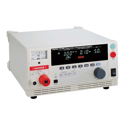
Hioki CLAMP ON LEAK HiTESTER 3283 User manual

3283
CLAMP ON
LEAK HiTESTER
INSTRUCTION MANUAL


Contents
Introduction i
Shipping Check ii
Safety iii
Points for Attention During Use vi
Organization of this manual xii
Chapter 1 Product Outline 1
1.1 Product Outline 1
1.2 Features 2
1.3 Parts and Functions 4
Chapter 2 Measurement Procedure 7
2.1 Preparations 7
2.2 Leak Current Measurement 〜A 8
2.3 Filter Function FILTER 14
2.4 Data Hold Function HOLD 15
2.5 Recording Function REC 15
2.6 Auto Power-Off Function APS 18
2.7 Battery Low Warning 19
2.8 Beep Tone 19
2.9 Fast Mode 20
2.10 Output Function OUTPUT 21
Chapter 3 Battery Replacement 25
Chapter 4 Attaching the Hand Strap 27

Chapter 5 Specifications 29
5.1 Measurement Specifications
(23℃±5℃, 80% RH max.) 29
5.1.1 AC current Arms (true rms indication) 29
5.1.2 Frequency Hz 30
5.2 General Specifications 31
Chapter 6 Troubleshooting 35
Chapter 7 Service 37

i
Introduction
Introduction
Thank you for purchasing this HIOKI "3283
CLAMP ON LEAK HiTESTER." To get the
maximum performance from the unit, please
read this manual first, and keep this at hand.
ARequest
We have tried to bring this manual as close to
perfection as we could achieve. If perchance
you find any unclear portions, mistakes,
omissions, or the like, we would be most
obliged if you could please notify us of them
via any HIOKI agent, or directly.

ii
Shipping Check
Shipping Check
When the unit is delivered, check and make
sure that it has not been damaged in transit.
In particular, check the accessories, panel
switches, keys, and terminals.
If the unit is damaged, or fails to operate
according to the specifications, contact your
dealer or HIOKI representative.
Check the 3283 Unit and the Supplied
Accessories
Main unit
3283 CLAMPONLEAKHiTESTER
Supplied accessories
9399 Carrying Case 1
Hand Strap 1
6F22(006P) 1
Instruction manual 1
Options
9094 OUTPUT CORD
9445 AC ADAPTER(UP01211090, POTRANS)

iii
Safety
DANGER
This equipment is designed according to IEC
1010 Safety Standards, and has been tested for
safety prior to shipment. Incorrect
measurement procedures could result in injury
or death, as well as damage to the equipment.
Please read this manual carefully and be sure
that you understand its contents before using
the equipment. The manufacturer disclaims all
responsibility for any accident or injury except
that resulting due to defect in its product.
Safety
This Instruction Manual provides information
and warnings essential for operating this unit
in a safe manner and for maintaining it in
safe operating condition. Before using this
unit, be sure to carefully read the following
safety notes.

iv
Safety
DANGER
Indicates that incorrect operation
presents extreme danger of accident
resulting in death or serious injury to
the user.
WARNING
Indicates that incorrect operation
presents significant danger of accident
resulting in death or serious injury to
the user.
CAUTION Indicates that incorrect operation
presents possibility of injury to the user
or damage to the equipment.
NOTE Denotes items of advice related to
performance of the equipment or to its
correct operation.
The following symbols are used in this
Instruction Manual to indicate the relative
importance of cautions and warnings.

v
Safety
This symbols is affixed to locations on
the unit where the operator should
consult corresponding topics in this
manual (which are also marked with the
symbol) before using relevant
functions of the unit.
In the manual, this mark indicates
explanations which it is particularly
important that the user read before using
the unit.
Indicates AC (Alternating Current).
Indicates DC (Direct Current).
Indicates a device which is double-
insulated.
Safety Symbols

vi
Points for Attention During Use
DANGER
・
・・
・When conductors being measured carry in
excess of the safe voltage level (SELV-E) and
not more than 300 V, to prevent short circuits
and electric shock while the clamp core jaw is
open, make sure that conductors to be
measured are insulated with material
conforming to (1) Overvoltage CategoryⅠ
ⅠⅠ
Ⅰ, (2)
Pollution Degree 2, and (3) Basic Insulation
Requirements for Working Voltages of 300 V.
Refer to the following standards regarding the
meanings of underlined terms.
IEC61010-1
IEC61010-2-031
IEC61010-2-032
・
・・
・Use clamp testers only on power lines up to 300
Vrms AC, to avoid short-circuits and accidents
that could result in injury or death.
・
・・
・Do not use clamp testers on bare conductors.
When the clamp core jaw is open, there is a risk
of short-circuits and accidents that could result
in injury or death.
Points for Attention During Use
In order to ensure safe operation and to
obtain maximum performance from the unit,
observe the cautions listed below.

vii
Points for Attention During Use
DANGER
・
・・
・Always connect the clamp sensor to the
secondary side of a breaker. On the secondary
side of a breaker, even if the lines are shorted
the breaker can trip and prevent an accident.
On the primary side, however, the current
capacity may be large, and in the event of a
short-circuits there may be a serious accident.
・
・・
・When using an AC adapter, use only the
specified HIOKI model 9445 (UP01211090,
POTRANS).

viii
Points for Attention During Use
WARNING
・
・・
・To prevent electric shock, do not allow the unit
to become wet and do not use the unit when
your hands are wet.
・
・・
・To avoid electric shock accidents, when
carrying out measurement on live lines, wear
proper protective gear, including insulating
rubber gloves, insulating rubber boots, and
safety helmet, and use extreme caution.
・
・・
・When measuring the ground conductor on a
transformer Class 2 connection site, be careful
not to approach high voltage devices or
conductors. Also, if close to high voltage
charging devices or if measurement is otherwise
difficult, first change the route of the grounding
wire.
・
・・
・To avoid electric shock when replacing the
batteries, first disconnect the clamp portion
from the object to be measured. Also, after
replacing the batteries, always replace the back
case before using the unit.
・
・・
・When replacing the batteries, be sure to insert
them with the polarity correct.
・
・・
・Do not short-circuits used batteries,
disassemble them, or throw them in a fire.
Doing so may cause the batteries to explode.
・
・・
・Be sure to dispose of used batteries according
to their type in the prescribed manner and in the
proper location.

ix
Points for Attention During Use
CAUTION
・Do not store or use the unit where it will be
exposed to direct sunlight, high temperature, high
humidity, or condensation. If exposed to such
conditions, the unit may be damaged, the insulation
may deteriorate, and the unit may no longer satisfy
its specifications.
・This is a precision instrument: do not clamp any
foreign objects in the end of the clamp core, or
insert anything in the core gap.
・To avoid damage to the unit, do not subject the unit
to vibrations or shocks during transport or handling.
Be especially careful to avoid dropping the unit. Do
not exert excessive pressure on the clamp sensor
or attempt to wedge the sensor into a tight spot for
measurement.
・Before using the unit, inspect it and check the
operation to make sure that the unit was not
damaged due to poor storage or transport
conditions. If damage is found, contact your dealer
or HIOKI representative.

x
Points for Attention During Use
CAUTION
・Do not exceed the maximum input current rating,
which depends on the frequency of the current
being measured (see Fig.).
Frequency [Hz]
Frequency-dependent deletion characteristics
Current [A]
・Do not use the unit if the battery is exhausted (when
the mark lights in the display area). Be sure to
replace the exhausted battery with a new one.
・When replacing the battery, make sure that the metal
battery snap fitting is firmly connected. If the metal
fitting is loose, adjust it and recheck the connection.
・Make sure the power is turned off before plugging in
or unplugging the AC adapter.

xi
Points for Attention During Use
NOTE ・For circuits which carry several superimposed
currents, correct measurements may not be
obtained.
・Accurate measurement may be impossible in
locations subject to strong external magnetic
fields, such as transformers and high-current
conductors, or in locations subject to strong
external electric fields, such as radio
transmission equipment.
・Gently wipe dirt from the surface of the unit
with a soft cloth moistened with a small
amount of water or mild detergent.
Do not try to clean the unit using cleaners
containing organic solvents such as benzine,
alcohol, acetone, ether, ketones, thinners, or
gasoline. They may cause discoloration or
damage.

xii
Organization of this manual
Chapter 1
Product Outline
Explains the parts and functions of the unit.
Chapter 2
Measurement Procedure
Explains how to use the 3283 for
measurement.
Chapter 3
Battery Replacement
Explains how to replace the battery used to
power the 3283.
Chapter 4
Attaching the Hand Strap
Explains how to attach the hand strap, for
easy handling of the unit in the field.
Chapter 5
Specifications
Lists the specifications of the 3283 CLAMP
ON LEAK HiTESTER.
Chapter 6
Troubleshooting
Describes points to check before requesting
service.
Chapter 7
Service
Explains how to get the unit serviced.

1
Chapter 1 Product Outline
Chapter 1
Product Outline
1.1 Product Outline
The3283CLAMPONLEAKHiTESTERis
designed for wide-range measurement on live
circuits, from very small leak currents up to
load currents of 200 amperes. The clamp part
is made of material with high magnetic
permeability, to minimize adverse effects
caused by external magnetic fields, and to
reduce tolerances due to the position of the
measured conductor.

2
Chapter 1 Product Outline
1.2 Features
・High-sensitivity range with 10-mA full-scale point
Allows accurate measurement even of minute
leak currents (resolution 10μA).
・Wide measurement range
Five range settings from 10 mA to 200 A
make the 3283 suitable for many applications.
・Microprocessor-controlled functions
In spite of the compact dimensions of the
unit, versatile functions such as SLOW and
MAX/MIN are made possible by the built-in
microprocessor.
・True rms indication
The true rms conversion circuit delivers
accurate results not affected by leak current
distortion.
・Filtering
The widespread use of switching power
supplies and equipment incorporating
inverter technology frequently causes
harmonics to be superimposed in the leak
current waveform. The filter in the 3283
allows two kinds of measurement, for leak
current caused by insulation faults and for
leak currents including harmonics.
・Output jack
The output jack allows easy connection to a
level recorder or other equipment (level
recorder output: DC, waveform output: AC).

3
Chapter 1 Product Outline
・Unaffected by external magnetic fields and
conductor position
The core and magnetic shield are made of
material with high magnetic permeability,
allowing precise measurement also in the
vicinity of transformers, electric motors and
other sources of magnetic fields. Since the
influence of the conductor position on the
measurement result is negligible, residual
current characteristics are not a problem even
when using the unit as a zero-phase
transformer.
・Low power consumption
Power consumption is less than 100 mVA,
allowing the unit to operate continuously for
up to 50 hours on a single 6F22 (006P1)
battery.
・Dual power supply design
The unit can be powered using the optional
9445 AC adapter (UP01211090, POTRANS) or
from a battery.

4
Chapter 1 Product Outline
Top and Side View ①
②
③
④
⑤⑥
⑦
⑧
1.3 Parts and Functions
Other manuals for CLAMP ON LEAK HiTESTER 3283
1
Table of contents
Other Hioki Test Equipment manuals

Hioki
Hioki 3288 User manual

Hioki
Hioki ST4030 User manual

Hioki
Hioki 3805-50 User manual

Hioki
Hioki HiLogger 3145-20 User manual

Hioki
Hioki 3504-40 C HiTester User manual

Hioki
Hioki 3257 User manual

Hioki
Hioki FT6380-50 User manual

Hioki
Hioki 3169-20 Instruction manual

Hioki
Hioki 3554 User manual

Hioki
Hioki FT6031-50 User manual

Hioki
Hioki FT4310 User manual

Hioki
Hioki 3804-50 User manual

Hioki
Hioki MR8827 User manual

Hioki
Hioki 3511-50 User manual

Hioki
Hioki MEMORY HiCORDER 8855 Instruction manual

Hioki
Hioki IR3455-01 User manual

Hioki
Hioki IM9202 User manual

Hioki
Hioki 3154 User manual

Hioki
Hioki 3244-60 User manual

Hioki
Hioki IR4055 User manual