ATD Tools ATD8601 User manual

ATD8601
ATD8601
InstructionManual
InstructionManual
ATD8601
InstructionManual
VER: V5
● Power supply for device is 3.7V rechargeable lithium battery.
● Disconnect the 5V 1A Charger when complete charging in fear of
danger.
● Please use battery according to the specification; otherwise, it
may result in damage to equipment.
● Never put the equipment in the place with much dust, humidity
and high temperature (over 40 ).
● Please never dismount the equipment arbitrarily. The maintain
-ance and care shall be conducted by professional personnel.
● Users can set the auto-off time according to his own needs.
● Please take out the battery in launcher and receiver if the
equipment is not used for a long time so as to prevent that the
battery liquid is leaked in future.
● Never use the equipment to detect power cord with electricity
(such as power supply circuit of 220V), otherwise, it may result
in damage to equipment and personal injury.
● Never conduct related operation of communication line in
thunderstorm weather so as to prevent lightning stroke and
Impact on personal safety.
Read the precautions before
your operation. CONTENTS
Overview.............................................................01
Main functions ...................................................02
Benefits..............................................................02
Technical Parameters.........................................02
Product interface and key introduction...............04
Instruction on Main interface..............................06
Charging function...............................................06
Operation steps..................................................07
a. Cable line-to-line test..........................................09
b. Port flash test.....................................................12
c. Cable length test.................................................14
d. Cable tracing test................................................21
e. Crosstalk test.....................................................23
f.POE test............................................................24
g.PING test...........................................................24
h.System set..........................................................26
Power off............................................................27
Accessories.......................................................27
Diagram of series products ................................28
Overview
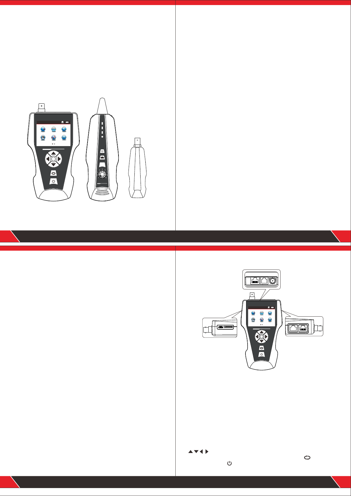
ATD8601 Series are newly developed by our company which are
capableofanti current interference . The equipment is composed of
three parts: main tester (ATD8601-M), receiver (ATD8601-S) and
remote identifier (ATD8601-R). It is a multifunction device, capable
of measuring cable length, cable tracing, cable continuity testing,
PoE and PING functions, also it can detect voltage presence. Users
can read the test results visually from the 3.7 inch color screen. All
these make this item be as a practical tool for low voltage system
installation and maintenance technicians of communication circuits
and comprehensive wiring circuits. It is widely used in the fields like
telephone system, computer networks and other metal lead circuits.
Remote identifier
(ATD8601-R)
Main tester
(ATD8601)
Receiver
(ATD8601-S)
01
OK
Pow er
CHG
NCV
SCA N
SET
RE CEIV ER
Cable Length T ester
NF-8601
WIREMAP
Cable Length Tester
EMIT TER
Menu
Mappin g Port F las h
POE
Scan
Length
Ping
● Capable to test open, short, cross connection, reverse, and
broken wire positioning with M-S, M-R method.
● To perform crosstalk test on network cable to solve the potential
problem of slow speed.
● Measure length of network cable, coaxial cable, telephone cable
and USB cable up to 2000m, no connection of remote unit.
● To quickly find the targeted cable without stripping isolation
among unknown cables.
● Port flash function helps locate the target network cable more easily
on the Router / switches with electricity.
● To trace cable on exchanger or Router without current interference.
● Locate breakage and short position accurately.
● Scanning cable on the POE Router.
● Detect PoE presence and how much the voltage is.
● PING Testing.
Main functions
Technical parameters
02
● Low voltage alarm function.
● Remote unit with tone when checking cable continuity.
● Functions of storage and memory.
● TF function: import and export data.(160 sets)
● Currency detection function and Lighting lamp for working in dark.
● Automatic delay power on-off and language selection: Chinese &
English.
● Single chip microprocessor software watchdog design is reliable
in operation.
Benefits
(1). Overall dimensions
Main tester: 173X92X34mm; Receiver: 183X58X35mm
Remote identifier: 106X32X30mm.
(2). Display
2.8 inch LCD Color screen:320X240 (Effective visible area
60X45mm).
(3). Power supply
3.7V rechargeable lithium battery1800mAh
(4). Tracing cable types
STP/UTP 5E, 6E network cable, telephone cable, coaxial cable,and
common metal wires connected with alligator clip.
(5). Testing cable types
STP/UTP 5E, 6E network cable, telephone cable, coaxial cable, and
common metal wires connected with alligator clip.
(6). Operating environment temperature/humidity
-10℃ ~ +60℃ /20% ~ 70%;
(7). Testing device interface
Main unit: RJ45 (M), RJ45 (S), PoE/PING, RJ11, BNC connector,
Remote identifier: RJ45, RJ11, BNC connector interface.
(8). Length measurement
Range: 1-2000m;
Calibration precision: 2% (+/-0.5m, or +/-1.5 feet); (calibration;
cable>10m) measurement precision: 3% (+/-0.5m, or +/-1.5 feet);
(AMP, CAT5E, 6E cable material)Display unit: meter, foot, yard.
(9). Length calibration, storage and data load
User can set a length value at a known length, store the value in the
system, which can be used for future choice (9 sets of data can be
stored). and the calibration length should be over 10m.
(10). Cable wiremapping
Open, short, reverse , cross, crosstalk, etc.
(11). PoE/PING Testing
(12). Tracing cable
Locate targeted cable among lots of cables.
(13). Automatic power-off
Users can choose time to turn off the tester automatically.
03
OK
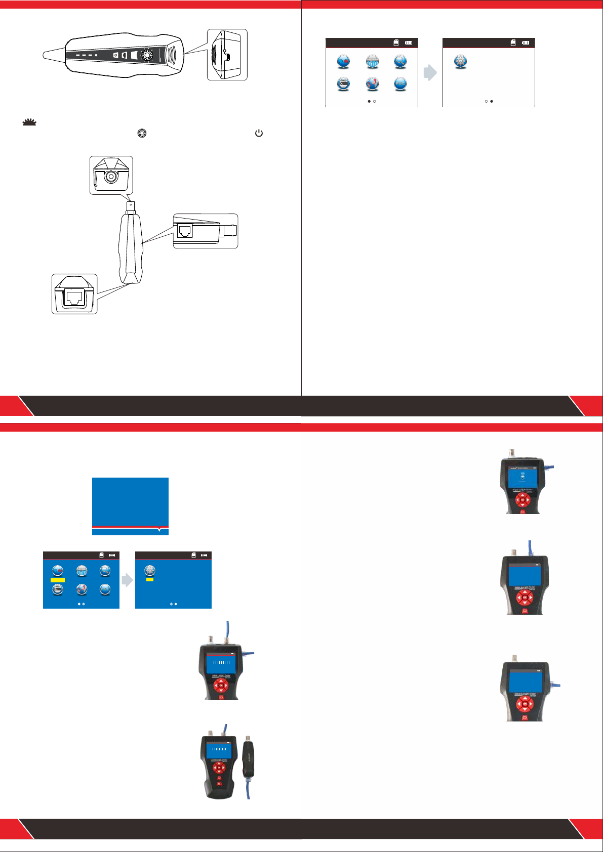
Product interface and key introduction
Main tester
BNC
RJ45
MAIN RJ11
RJ45
SCAN
PoE/Ping
CHG TF Card
04
(1) . Three RJ 45 ports on the main unit:
One of them is “MAIN” port, used for cable length measuring and continuity
testing. and another one is “SCAN” interface , used for cable tracing and
continuity testing locally; The other one is “PoE/Ping” interface, used for
PoE and PING Testing.
(2) Port RJ11: used for tracing cable, cable length and continuity testing for
telephone cable .
(3) Port BNC: used for tracing cable, cable length and continuity testing for
coaxial cable.
(4) MICRO: Charging for battery.
(5) TF: Store and export datas (txt format / 160sets can be stored).
Ports on Main unit
Function keys on Main tester
means up/down/ left/right when moving moving cursor to select
functions on Menu. Press “OK” to confirm or start testing. means return
to last menu.Press to turn on or turn off the device.
Cable Length Tester
EMITT ER
Menu
Map ping P ort Fla sh
POE
Sca n
Len gth
Ping
Powe r
CHG
NCV
SCAN
SE T
REC EIVE R
Cable Length Tester
Receiver
Remote identifier
CHG
05
Function keys on Receiver
is to detect currency and also lighting lamp. “SET” is for voltage
detector and cable tracing. Press to adjust the sensitivity. Press to
turn on or turn off the device.
(1)Port RJ45: remote testing cable continuity for Lan cable.
(2)Port RJ11: remote testing cable continuity for telephone cable.
(3)Port BNC: remote testing cable continuity for COAX cable.
Ports on Remote identifier
NF-860 1
WIREMAP
06
Instruction on Main interface
Here are seven main functions on Main interface.
(1) .Mapping --- Test cable continuity, such as the cable is good, open,
short, cross, reverse connection, etc.
(2).Port flash---For port flash function can help you locate the target
network cable more easily while connect the Router / switch.
(3).Scan ---to find targeted cable among lots of network cables,
telephone cables, USB cables and coaxial cables, also tracing short
position of cable.
(4).PING---to test network signals and the network cable is connected or not.
(5).Length---Pairing and length measurement: verify cable length,
open circuit distance and pairing, crosstalk.
(6).PoE ---to test if a network cable is connected with PoE switcher or Router,
and then detect the power of every cable.
(7).Set---Set up backlight/ backlight time/ auto-off time/ theme color/ data export/
system information (version No.),ect.
Charging function
The power supply for main tester and receiver are both 3.7V Rechargeable
battery, its capacity is 1800mAh. When finish charging, the main tester can
work continuously for over 20hs, receiver can work for over 50hs. The
rechargeable battery avoids the trouble of replacing 9V battery again and
again. The whole standard charging devices are included. After charging,
please disconnect the charging device, otherwise it would shorten the
battery life.
When the emitter low battery(<3V), it will show “Low battery, auto-off
soon! ” ; when the reciever low battery(<3V), “power” will flash.
Menu
Mapping Por t Flash
POE
Scan
Length
Ping
Menu
Set
Graph No.1
Graph No.2
07
Boot screen
Turn on the tester to come to home page.
Operation steps
3 seconds later, the following main interface will be displayed:
Users can set up the systems according to his own needs and to have next
operations.
(1) M-S Method--- Checking cable continuity
with main tester for Lan cable Connect one
end of lan cable into “Main” port, the other
end to “Scan” port. ( Graph No.1)
Note: M-S Method is only for Lan cable continuity
testing, not for other kinds of cables.
Testing methods
(2) M-R Methods---Checking cable continuity
with main tester and remote unit, for Lan cable,
telephone cable, coax cable. ( Graph No.2)
Note: M-R Methods is for cable continuity
testing, not for cable length measuring.
ATD8601
Your excellent
helper in cable test!
1 2 3 4 5 6 7 8 G
M:
S:
1 2 3 4 5 6 7 8 G
RJ45 M appin g
Test mod e: Loca l
OK !
1 2 3 4 5 6 7 8 G
M:
R:
1 2 3 4 5 6 7 8 G
RJ45 M appin g
Test mode : Remot e
OK !
Mappi ng Port Flash
POE
Scan
Menu
Lengt h
Ping
Set
Menu
Sca n
Sca nning ...
Graph No.3
Graph No.4
Graph No.5
08
(3) Scan method---“ RJ45 Scan”“RJ11”“ BNC”
ports are used to trace corresponding cables.
( Graph No.3)
(4) Open Method--- Only connect one end of
cable into main tester when measuring cable
length, don't connect with remote or terminator.
( Graph No.4)
(5) PoE/ PING Methods--- Connect one end
of lan cable with “POE/Ping” Port, the other
end to PoE switcher or router. ( Graph No.5)
RJ45 Le ngth
1 Open 10 5.3m
2 Open 1 05.3m
3 Open 1 05.3m
4 Open 1 05.3m
5 Open 105 .3m
6 Open 10 5.3m
7 Open 105. 3m
8 Open 1 05.3m
Total le ngth:
105.3m
Pin g
Pi ng 192 .168 .1.1 w ith 32 b ytes o f dat a:
Re ply fr om 192 .168 .1.1 : time =1m s TTL= 64
Re ply fr om 192 .168 .1.1 : time =1m s TTL= 64
Re ply fr om 192 .168 .1.1 : time =1m s TTL= 64
Re ply fr om 192 .168 .1.1 : time =1m s TTL= 64
Pi ng sta tist ics f or19 2.1 68.1 .1
Pa cket s: Sen t=4 , Rece ive d=4, L ost= 0
Ap prox imat e rou nd tri p tim es in ms :
Mi n=1m s , Max= 1ms , A vera ge= 1ms

Data upload
Start
Testing ...
Cable open or too short!
x x 3 4 5 6 7 8 G
M:
R:
X X3 4 5 6 7 8 G
Wire Map:Remote
a. Cable line-to-line test ( eg: Network cable):
After entering main menu, move the cursor button to cable on-off test.
Then press OK; at this time, choose network cable, press OK, it
will enter into test the network cable menu. And after that, choose START
and connect the RJ45, the result will show you directly; but you also can
export the data and the tested result will into the TF card, the following
interface is shown indicating test is in process:
Test result 1: Unload or the cable not connected well
If the cable does’t connect to the main tester interface, it will show
as below:
At this time, press to return to the main menu, and then press
“ENTER” key for re-test.
Test result 2: Short circuit
If there is short circuit with the cable and terminal, it will show as below:
(Short circuit with 1 and 2)
At this time, press to return to the main menu, and then press “ENTER”
key for re-test.
09
Mappi ng
RJ11 BNC
RJ45 CAT6
RJ45 Ma ppi ng
RJ45 Mapping
RJ45 Mapping
RJ45 Ma ppi ng
Short mapping: 12
Mappin g Port F lash
POE
Scan
Menu
Length
Ping
12345678G
M:
R:
1 2 3 4 5 6 7 8 G
1 2 X 4 5 6 7 8 G
M:
S:
1 2 X 4 5 6 7 8 G
Open mapping: 3
1 2 3 X X 6 7 8 G
M:
R:
1 2 3 X X 6 7 8 G
Test result 3: correct connection
If the device connects corrected, the tester can check remote identifier (R),
or local port (S) cables. If verify the tested cable with remote ( R) or local
port (S), it can test STP network cable , and the picture will show you as
below :
R = Remote identifier's foot for RJ 45
S= Local foot of RJ45 port for scan
M= Local foot for RJ45 main interface
G = STP network cable
If you press it means back to the last menu and press OK means test
again or back to the main menu for re-test.
Test result 4: open circuit (Local testing with Main tester)
When local test and meet open circuit, it will show as below:
In the figure, “X” shown in “3” position, indicates there is open circuit.
Note: Because network cable is made of pair cores, if there is open circuit,
it will show faults in pairs, just as above "4" &" 5". it means either "4" pin or
"5" pin exists an open circuit, or both "4" and "5" exist an open circuit.
Test result 5: open circuit (Remote testing with Remote unit)
In the figure, “X” shown in “4” and “5” pin position, indicates there is open
circuit in “4” and “5” pin of the remote pin.
10
RJ45 Mapping
Test mode: Re mote
OK !
Test mode:L ocal
RJ45 Mapping
RJ45 Mapping
Open mapping: 45
Test mode: Re mote
X X 3 X X 6 7 8 G
M:
R:
X X 3 X X 6 7 8 G
1 2 3 4 5 6 7 8 G
M:
R:
1 2 3 4 5 6 7 8 G
Note: Because network cable is twisted pair cables, if there is open circuit,
it will show faults in pairs, just as above "4" &" 5". it means
either "4" pin or "5" pin exists an open circuit, or both "4" and "5" exist an
open circuit.
11
Test result 6: Cross (out of order )
When the cables have cross situation , it will show you as below :
Test result 7: Short , Open , Cross
If the cables and remote meet short , open and cross together , will show
you this result : ( 2 is short , 4 and 5 open , 7 and 8 was cross ):
Test result 8: Continuity test for CAT6
It's the same result with Network cable test ,it will show as below:
Test result 9: Continuity test for 6 pin RJ11
The 6-core RJ11 should insert into the telephone interface and the test
method and show result is the same with RJ45.
RJ45 Mapping
Test mode: Re mote
RJ45 Mapping
Test mode: Re mote
Data upload
Start
Testing ...
Data upload
Start
Testing .. .
CAT6 Mapping CAT6 Mapping
RJ11 Mapping R J11 Ma ppi ng
Cross mapping: 78
Short mapping: 12
Cross mapping: 78
Open mapping:45
BNC
Mapping
RJ11
RJ45 CAT6
BNC
Mapping
RJ45 CAT6
RJ11
Mappin g Port F lash
POE
Scan
Menu
Length
Ping
Mappin g Port F lash
POE
Scan
Menu
Length
Ping
12
Test result 10: Continuity test for BNC cable
When you test the BNC cable , you should insert into the BNC interface
and the test method is the same with RJ45.
Remote unit with tone when checking wiremap
When use remote unit to check wiremap, users can distinguish the test
result firstly via tones. When the cable is normal, the remote unit will
generate “ beep ” long and slowly.
When the cable is abnormal, the the remote unit will generate “ beep ”
short and quickly.
Attention 1: The cable continuity testing is only for more than 2-core
cables , it's useless for single cable.
Attention 2 : When test cable continuity with remotes, the remote will not
generate “beep” if the cable is in the below situations.
1. network cable: any pin between pin #7 or #8 is broken,
2. telephone cable: any pin between pin #1 or # is broken,
3. 6P/4C , 6P/2C telephone cable and coax cable.
Data upload
Start
Testing .. .
BNC Map pin g BNC Map pin g
Mapping
RJ45 CAT6
RJ11 BNC
Mappin g Port F lash
POE
Scan
Menu
Length
Ping
b.Port flash testing:( Network cable scanning only )
After entering main menu, move the cursor button to Port Flash .
Connect the network cable into PING/POE port for one side, and the other side
connect the Router.when you enter port flash test function, it will show a and
if the tested network cable is good , the LCD will show a and at the same time
the Router port will keep flashing which the cable connected to. That will help
you to locate the target cable more convenient. The image as below:
Mappi ng Port Flash
POE
Scan
Menu
Lengt h
Ping
Port Flash Port Flash

13
Special Use: network detection
The device can test line sequence under the switches work on.
Network cable as the example---One side connect the main tester's RJ45
interface and the other side connect the switch , then you can press the
test button directly , if the connect is right , will show you as below ( when
the switch is 8 cores )。
But if the Pin1 & Pin2 of the tested switch was open , the testing result will
display as below. (when the switch is 8 cores).
Attention:
This method is only to test lan cable which is open or good connection ,
can't test cross and short.
XXXXXXXX
M:
R:
X X X X X X X X
RJ45 Mapping
Test mode: Re mote
Short mapping: 12345678
XXXXXXXX
M:
R:
X X X X X X X X
RJ45 Mapping
Test mode: Re mote
Short mapping: 345678
Open mapping:12
This is the especial test result display when check cable wiremapping
connected to switcher. Since the switcher is shorted itself, that's why
the result is short mapping, but it still means the cable is good.
Mappin g Port F lash
POE
Scan
Menu
Length
Ping
Length
RJ11 BNC
RJ45 CAT6
RJ45 Length
Calibr ati on
Unit:M ete r
Testing. ..
Data upl oad
Load Dat a
Cable Le ngt h
14
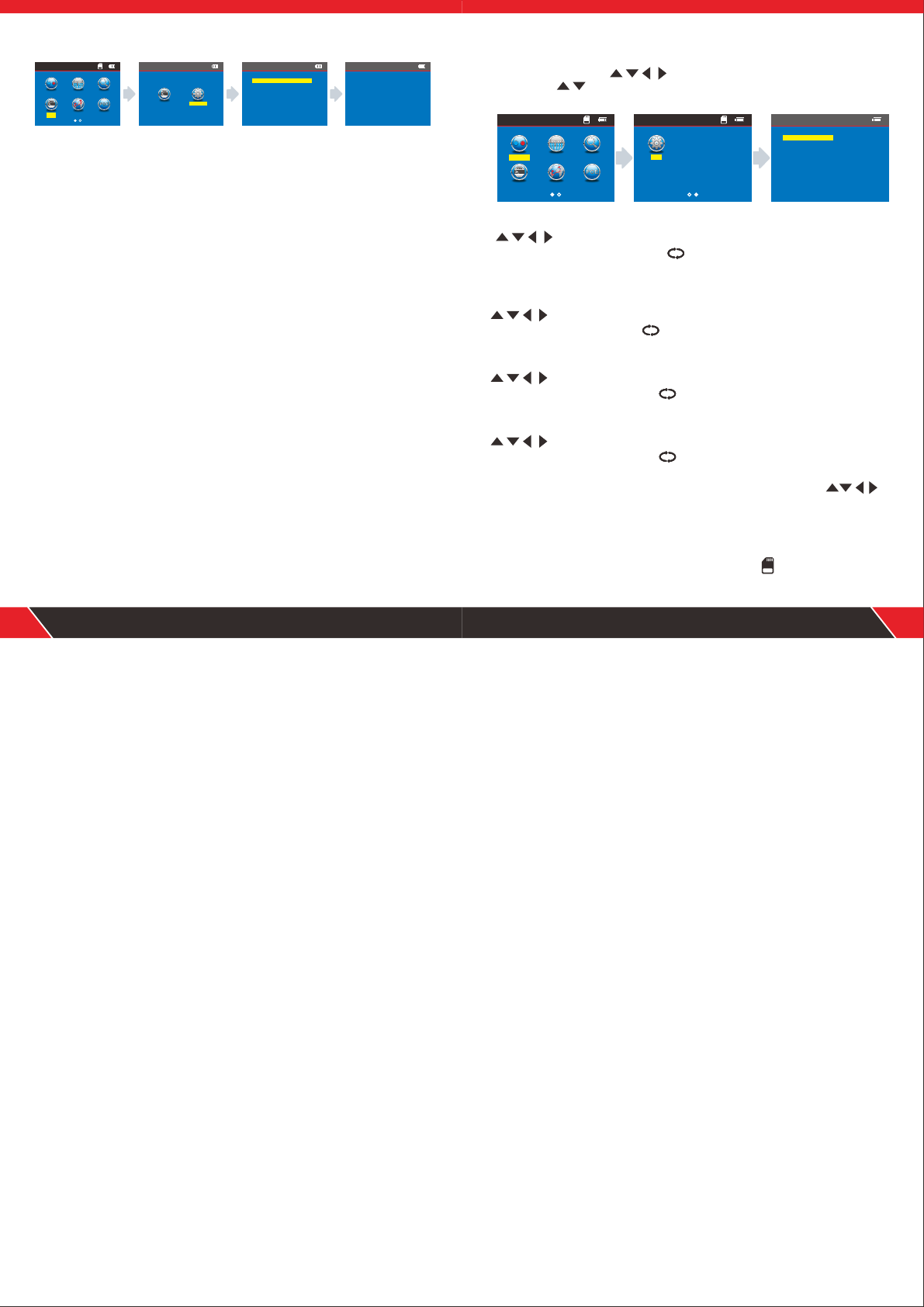
c.Cable length test:( eg: Network cable)
After entering main menu, move the cursor button to Cable
length test. Then press OK; at this time, choose network cable, press OK,
it will enter into test the network cable menu. After that, choose START
and connect the RJ45 port “M” , the the other side connect nothing ,
result will show you directly; but you also can export the data and the
tested result will into the TF card, the following interface is shown indicating
test is in process:
They are 5 items for your choose:
1. Unit---can set up Meter , inch , yard.
2. Calibration---to calibrate different types of cables.
3. Load data---to call out the saved data.
4. Data upload---to export the data of the tested cable length.
5. cable length---Testing cable length.
Attention 1 : You can not connect the local port ( S) , and also can't
connect the remote ( R) when you test the cable length . you just connect
nothing with the other side.
Attention 2 : Due to different technical parameters with different branded
cables, users are recommended to use dynamic calibration function of the
equipment before measuring length (Refer to the related chapter for more
details.).
Attention 3 : If there is much difference in length for every pin, pls take the
data for pin 3 as a standard reference for the network cable.the data pin 4
for the telephone cable ; the data pin 2 for the BNC cable.
Attention 4:the device is only used to test more than 2-core cables’ length
(2-core included), not available for single-core cable , when test 2-core
cables,if the cable is broken , the length shows on the screen is the break
location.
RJ45 Length
15
Test result 1: The commonly used Network cable
The normal network cable length test result show you as below:
From the image you can see the total length is 105.3 M, press back to
the main menu and then enter the next testing.
Test result 2 : Short circuit
If there is short circuit with the cable and terminal, the following interface is
shown (Short circuit with 1 and 2 )
The total length is 105.3M, but it also means that here is a short location
at 50.8 M in pin 1 & 2.
At this time, press to return to the main menu, and then press “ENTER”
key to other functions.
RJ45 Length
1 Open 105.3m
2 Open 105.3m
3 Open 105.3m
4 Open 105.3m
5 Open 105.3m
6 Open 105.3m
7 Open 105.3m
8 Open 105.3m
1 O p e n 5 0 . 8 m
2 O p e n 5 0 . 8 m
3 O p e n 1 0 5 . 3 m
4 O p e n 1 0 5 . 3 m
5 O p e n 1 0 5 . 3 m
6 O p e n 1 0 5 . 3 m
7 O p e n 1 0 5 . 3 m
8 O p e n 1 0 5 . 3 m
s h o r t e n l o c a t i o n f o r P i n 1 2 : 5 0 . 8 m
T o t a l l e n g t h : 1 0 5 . 3 m
Total length:
105.3m
RJ45 Length
1 Short 50.8m
2 Short 50.8m
3 Open 105.3m
4 Open 105.3m
5 Open 105.3m
6 Open 105.3m
7 Open 105.3m
8 Open 105.3m
Short mapping:
12Short- L: 50 .8m
Total length:
105.3m
16
Test result 3 : Normal CAT6
The normal cat 6 cable length test result show you as below:
At this time, press to return to the main menu, and then press “ENTER”
key to other functions.
Test result 4 : Short circuit of cat 6
The cable length of cat 6 when it short circuit, image show you as below:
The total length is 105.3M, but the cable test result is 50.8 M on the screen ,
that means it has a short circuit at the length 50.8M.
1 O p e n 5 0 . 8 m
2 O p e n 5 0 . 8 m
3 O p e n 1 0 5 . 3 m
4 O p e n 1 0 5 . 3 m
5 O p e n 1 0 5 . 3 m
6 O p e n 1 0 5 . 3 m
7 O p e n 1 0 5 . 3 m
8 O p e n 1 0 5 . 3 m
s h o r t e n l o c a t i o n f o r P i n 1 2 : 5 0 . 8 m
T o t a l l e n g t h : 1 0 5 . 3 m
CAT6 Length
1 Open 105.3m
2 Open 105.3m
3 Open 105.3m
4 Open 105.3m
5 Open 105.3m
6 Open 105.3m
7 Open 105.3m
8 Open 105.3m
Total length:
105.3m
1 O p e n 5 0 . 8 m
2 O p e n 5 0 . 8 m
3 O p e n 1 0 5 . 3 m
4 O p e n 1 0 5 . 3 m
5 O p e n 1 0 5 . 3 m
6 O p e n 1 0 5 . 3 m
7 O p e n 1 0 5 . 3 m
8 O p e n 1 0 5 . 3 m
s h o r t e n l o c a t i o n f o r P i n 1 2 : 5 0 . 8 m
T o t a l l e n g t h : 1 0 5 . 3 m
CAT6 Length
1 Short 50.8m
2 Short 50.8m
3 Open 105.3m
4 Open 105.3m
5 Open 105.3m
6 Open 105.3m
7 Open 105.3m
8 Open 105.3m
Short mapping:
12Short- L: 50 .8m
Total length:
105.3m

Test result 5 : Normal 6 cores telephone cable
When test Telephone cable length ,connect one end of cable to port“RJ11"
choose menu of “cable length” for "RJ11"NO connection to the other end,
the result will show as below.
From the image , you can see the cable length is 95.6M , press return
the main menu and start other testing.
Test result 6: 6-core telephone cable with short circuit
When test Telephone cable length ,connect one end of cable to port“RJ11"
choose menu of “cable length” for "RJ11"NO connection to the other end,
the result will show as below.
The cable length is 95.6M, #1 & #2 has a short circuit in the location of
30.8M.
17
RJ11 Length
1 Open 95.6m
2 Open 95.6m
3 Open 95.6m
4 Open 95.6m
5 Open 95.6m
6 Open 95.6m
Total length:
95.6m
1 O p e n 5 0 . 8 m
2 O p e n 5 0 . 8 m
3 O p e n 1 0 5 . 3 m
4 O p e n 1 0 5 . 3 m
5 O p e n 1 0 5 . 3 m
6 O p e n 1 0 5 . 3 m
7 O p e n 1 0 5 . 3 m
8 O p e n 1 0 5 . 3 m
s h o r t e n l o c a t i o n f o r P i n 1 2 : 5 0 . 8 m
T o t a l l e n g t h : 1 0 5 . 3 m
RJ45 Length
1 Short 30.8m
2 Short 30.8m
3 Open 95.6m
4 Open 95.6m
5 Open 95.6m
6 Open 95.6m
Short mapping:
12Short- L: 30 .8m
Total length:
95.6m
Test result 7: BNC cable length test
When test BNC cable length ,connect one end of cable to port“BNC"
choose menu of “cable length” for NO connection to the other end,
"BNC"the result will show as below.
This result show you the cable length is 60.2M , press back to main
menu and enter other testing.
Test result 8 : BNC cable length test with short circuit
When test BNC cable length ,connect one end of cable to port“BNC"
choose menu of “cable length” for "BNC"NO connection to the other end,
the result will show as below.
This result show you the cable length is 20.7M , press back to main
menu and conduct other testing.
18
BNC Length
1 Open 60.2m
2 Open 60.2m
Total length:
60.2m
BNC Length
1 Short 20.7m
2 Short 20.7m
Short mapping:
12Short- L: 20 .7m
Total length:
20.7m
Lengt h
RJ11 BNC
RJ45 CAT6
RJ45 Calibr ati on
Calibr ati on
Unit:M ete r
Data upl oad
Load Dat a
Cable Le ngt h
Tseting ...
13.3Mete r
13.7Me ter
Calibr ati on 1
Calibr ati on 2
Calibr ati on 3
Calibr ati on 4
Calibr ati on 5
Calibr ati on 6
Calibr ati on 7
Calibr ati on 8
Calibr ati on 9
Return
Savin g.. .
Calibration: eg: Network cable
Due to different technical parameters with different branded cables, users
are recommended to use dynamic calibration function of the equipment
before measuring length (Refer to the related chapter for more details).
After entering main menu, move the cursor button to Cable
length test. Then press OK; at this time, choose network cable, press OK,
it will enter into test the network cable menu. And after that, choose
CALIBRATION (this cable need more than 10 M to calibrate, press to
add and to reduce the length) then press OK to save the data, the details
show you as below:
The method of cable length test for parameter callout: eg: Network cable
as Due to different technical parameters with different branded cables,
We recommend users to calibrate a given-length cable before measuring
length (Refer to the related chapter for more details.).
19
RJ45 Calibr ati on
RJ45 Cal ibr ationRJ45 Cal ibr ationRJ45 Cal ibra tion S ave
RJ45 Cal ibra tion S ave
press on ce, + 0.1m
press on ce, -0.1m
long pre ss to s et the data q uickly
press "o k "to s tore the da ta
Mappin g Port F lash
POE
Scan
Menu
Length
Ping
Load!
Data saved to:LONGRJ45 .TX T
After entering main menu, move the cursor button to Cable
length test. Then press OK; at this time, choose network cable, press OK,
and choose “Load Data” , press OK to choose the data saved.
Data export: eg: Network cable
After entering main menu, move the cursor button to Cable
length test. Then press OK; at this time, choose network cable, press OK,
and choose data export menu, press OK and show you “ data saved into
LONGRJ45.TXT “ that means the network cable length export to TF card .
20
RJ45 Leng th
Calib rat ion
Unit: Met er
Data up loa d
Load Da ta
Cable Length
RJ45 Lo ad Da ta
Calib rat ion 1
Calib rat ion 2
Calib rat ion 3
Calib rat ion 4
Calib rat ion 5
Calib rat ion 6
Calib rat ion 7
Calib rat ion 8
Calib rat ion 9
Retur n
RJ45 Lo ad Da ta
RJ45 Dat a Upl oad
Length
RJ11 BNC
RJ45 CAT6
RJ45 Le ngt h
Calibr ati on
Unit:M ete r
Data upl oad
Load Dat a
Cable Le ngt h
Lengt h
RJ11 BNC
RJ45 CAT6
Mapping Por t Fla sh
POE
Scan
Menu
Length
Ping
Mappin g Port F lash
POE
Scan
Menu
Length
Ping

Mappin g Port F lash
POE
Scan
Menu
Length
Ping
Scan
Scanning...
button on the receiver used to control lighting and detect currency;
button is sensitivity control when you find the cables.
The receiver charge : when connected the receiver charge , The light will
shining near the MICRO , and the same time , the charge Indicator light will
flashing , after full of power , this light will always lit.
21
Scan
Scanning. ..
--POE switch--
d. Cable scanning
The advanced version ATD8601, it has three modes for option.
(Low frequency, PoE switch, High frequency)
Firstly, choose icon “SCAN” on the main menu (Graph 1), enter to a default
scan mode, which is “low frequency” mode (Graph 2). Press “Up\Down”
button to switch scan modes to “PoE switch “ (Graph 3) or “High frequency”
(Graph 4) mode according to your
working environments.
Scan
Scanning...
--High frequency--
Graph 1
Graph 2
Graph 3
Graph 4
--low frequency--
Caution:
1. The scan mode in the tranmistter and receiver must be same, If the modes are not
matched correctly,even the receiver touch the correct cable, it won't generate tone,
either. (How to match the mode accordingly, see the following part of “usage of receiver”)
2. Users must choose “PoE switch” mode if scan cables connected to PoE switch.
Press to turn on the receiver, the “power” indicator is lit on, which
means it works normally. “SET” button is for choosing scan modes or voltage
detecting.
a) Short press “SET” one time, the “ SCAN” indicator will turn red, in this
situation, it is available for two scan modes: Low frequency / PoE switch.
It means, when the “scan” indicator is red, users must choose “ Low frequency”
or “PoE switch” mode in the transmitter.
b) Short press “SET” two times, the “ SCAN” indicator will turn purple, in this
situation, it is only available for “High frequency “ mode. It means, when the
“scan” indicator is purple, users must choose “ High frequency” mode in the
transmitter.
c) Long press “SET” for 2-3 secs, the “NCV” indicator will turn red, in this
situation, the receiver can be used as a voltage detector.
Usage of Receiver
1. Tracing Telephone /Lan cable which is connected to switch or router.
Insert the cable into port “RJ11”/ “RJ45 Scan”, enter “SCAN” menu to choose
“Low frequency” mode . Then turn on the receiver, press “SET” button one time
until the “SCAN” indicator turn red, then go to the other side to trace the target
cable.
(Note: telephone cable into “RJ11” port, Lan cable into “RJ45 Scan” port)
2. Tracing Coax cable
Insert the cable into port “BNC”, enter “SCAN” menu to choose “Low
frequency” mode . Then turn on the receiver, press “SET” button one
time until the “SCAN” indicator turn red, then go to the other side to trace
the target cable.
22
Mappin g Port F lash
POE
Scan
Menu
Length
Ping
Connection diagram of crosstalk line pair
1
2
3
6
4
5
7
8
1
2
3
6
4
5
7
8
1 2 3 4 5 6 7 8
1 2 3 4 5 6 7 8
1 2 3 4 5 6 7 8 G
M:
R:
1 2 3 4 5 6 7 8 G
e. Crosstalk test
As shown the figure below: it shows 3, 6 and 4, 5 with crosstalk. The line
pair With crosstalk will flash to indicate failure. If the testing cable is
crosstalk, Which will slow down the network speed:
Crosstalk interface is shown as below:
Note: In case of the non-twisted-pair cable like telephone cable,
Due to over large crosstalk, it generally shown as crosstalk.
f. POE test
After enter the main menu , press this cursor to move , and
point to POE test menu , and press OK to test POE; Take one side insert
the “POE/Ping “ PORT , the other side insert into POE Router or Ethernet ,
then start testing , and press OK , the screen will show you the voltage of
each pin.
23 24
RJ45 Mapping
Test mode : Remote
Data upl oad
Start
POE
Cross over:3 4 5 6
crossover pins flicker
1
2
3
4
5
6
7
8
50.0V
50.0V
0.0V
0.0V
POE
Tseting ...
POE
Mappin g Port F lash
POE
Scan
Menu
Length
Ping
Data upload
Start
POE
Data saved to:POE.TXT
Ping
Config ure
Ping
Ping
Ping Data upl oad
Data saved to:PING.TXT
If you want to save the tested result, you can choose data export into the
TF card, the picture show you as below:
g. PING test:
After enter the main menu , press this cursor to move to “Ping”
test , and press OK to test Ping; Take one side insert the “PING “ PORT ,
the other end connect to router or switcher , then start testing,the screen
will show you the test result as below.
If you want to save the tested result, you can choose data export into the
TF card and choose “PING.TXT”, the picture show you as below:
POE Data upload
Pi ng 1 92 .1 68 .1 .1 w it h 32 b yt es o f da ta :
Re pl y fr om 1 92 .1 68 .1 .1 : ti me =1 ms T TL=64
Re pl y fr om 1 92 .1 68 .1 .1 : ti me =1 ms T TL=64
Re pl y fr om 1 92 .1 68 .1 .1 : ti me =1 ms T TL=64
Re pl y fr om 1 92 .1 68 .1 .1 : ti me =1 ms T TL=64
Ping stat is ti cs f or 19 2. 16 8. 1. 1
Packets : Se nt =4 , Re ce iv ed =4 , Lo st =0
Approxi ma te r ou nd t ri p ti me s in m s:
Min=1ms , Max=1ms , Average=1ms
Ping
Config ure
Ping
Data upl oad
Start
Ping
De st in ati on I P: 192 .1 68 .1. 1
Data upload
St ar t
Ping
De st in ati on I P: 192 .1 68 .1. 1
Mapping Por t Fla sh
POE
Scan
Menu
Length
Ping
Mappin g Port F lash
POE
Scan
Menu
Length
Ping
Parameter specification of PING functions
IP address: can obtain automatically any Internet device which has
connected in the global. (Under a specific situation, users need to manually set
IP address when can't be automatically obtain IP address.)
Local IP address:It can be set up,but it must be different with other LAN devices.
Default gateway / Router: In the local LAN Router or gateway IP address.
Subnet mask: In the local LAN Subnet mask Remark :
Default gateway or Router or Subnet mask can be found by the same LAN
internet; Start – operate – impute CMD, Start the command line program ,
after that type “ ipconfig “ can query it.
Data packet: can be set based on needs.
Usage :
1. LAN communication device
Destination IP address was set to any one of computer in the same LAN , it
can test the LAN whether is normal between mainframes.
2. Network communication test
Destination IP address was set to any one of external network , such as
180.97.33.108, it can test the LAN whether is normal between mainframes.
Instructions of the test result:
The host tester will send four 32 bytes data packages to the garget device ;
The time means the host tester Communication back and forth between the
target device, that can judge the Communication if Stable and reliable.
When it shows 1ms, it means the Communication quality is great.
TTL : the quantity between the host tester and the target device passed
router or default gateway , TTL will reduce 1 when pass one router or
default gateway , it can reflect network' s topology . When TTL=4, it means
the host tester connected the target device directly.
h. System set:
When moving cursor “ ” to “Setup” item, press “OK” key . Move
the cursor “ ”to the relative test . The following interface will be shown:
25 26
Your excellent helper in cable test!
Ping
Ping Config ure
1. Backlight brightness: After entering main menu, move the cursor button
to backlight brightness.Then press OK;at this time,3 kinds them
for you choose, press OK, press back to the main menu again to begin
other test.
Configure
Ba se S et ti ng :
Au to -o bt ai n
La ca l IP : 1 92 .1 68 .0 .1 07
De fa ul t Ro ut er : 19 2. 16 8. 0. 1
Su bn et M as k : 25 5. 25 5. 25 5. 0
IC MP P ac ke t Se tt in g:
Pa ck et S iz e: 3 2 by te s
Ti me O ut : 2 00 0 ms
TT L : 64
Am ou nt : 4
Configure
Lac al I P : 19 2. 168 .0 .1 07
Def au lt R ou ter : 19 2. 16 8.0 .1
Sub ne t Ma sk : 2 55. 25 5. 25 5.0
Mappin g Port F lash
POE
Scan
Menu
Length
Ping
Set
Backlight: Level 3
Light time: 15s
Auto OFF: 15min
Systerm theme: Blue
Data export
Systerm information
Return
Mappi ng Port Flash
POE
Scan
Menu
Lengt h
Ping
Set
Menu
2. Backlight time : After entering main menu, move the cursor button
to backlight time . Then press OK; at this time, 15s,30s,1min for
you choose, press OK, press back to the main menu again to begin other
test.
3. Auto power-off : After entering main menu, move the cursor button
to Auto power-off . Then press OK; at this time, 5 kinds of them
for you choose, press OK, press back to the main menu again to begin
other test.
4. System theme: After entering main menu, move the cursor button
to System theme . Then press OK; at this time, 2 kinds of them
for you choose, press OK, press back to the main menu again to begin
other test.
5.Data export: After entering main menu, move the cursor button
to Export data . Then press OK; at this time, you can export all of the data
which you saved into the TF card that makes you can check them more
convenient on computer.
(When you export the data , you just insert the TF card , when you do this
step ok , it will show you a battery symbol on the left .)
Table of contents
Other ATD Tools Test Equipment manuals

ATD Tools
ATD Tools 5567 User manual

ATD Tools
ATD Tools ATD-5614 User manual

ATD Tools
ATD Tools ATD-5614 User manual

ATD Tools
ATD Tools 5489 User manual

ATD Tools
ATD Tools ATD5490 User manual

ATD Tools
ATD Tools ATD-5614 User manual

ATD Tools
ATD Tools ATD-5494 User manual

ATD Tools
ATD Tools ATD-5493 User manual

ATD Tools
ATD Tools ATD-3305 User manual

ATD Tools
ATD Tools 5573A User manual


