Titus Quasi-Moto User manual
1711 West University Drive, Suite157
Tempe, AZ 85281
480-894-8452 or 1-800-85-TITUS or Titus ycles@titusti.com
Drop The Bomb. You want to hit it and hit it big? Switch between 4.5" and 6" of rear wheel travel,
run up to 3" tires, and still have a triple chainring to get up the hills. All cartridge bearings provide
smoother-than-butter performance, with 4 mega-sized bearings at the main pivot for solid, reliable
tracking no matter how hard you're hitting what's coming at you. heck out the limited edition
"OnePointFive" model for the hardest core of the drop-in set.
The Quasi-Moto is the most versatile bike ever made. We start with a front triangle that can take
anything that you can dream up. Freeride, Downhill, Jumping, this bike can handle it all. You can
even run the bike with anything from a 4"-7" travel fork- Single or Dual crown. The travel adjust
feature allows you to switch between a 4.5" trail bike setting or 6 plush inches of the highest quality,
fully-active travel you have ever experienced. hoose between an air shock or coil-over, The Quasi
has the proper settings for both. The new seat tower design offers clearance for reservoir shocks as
well.
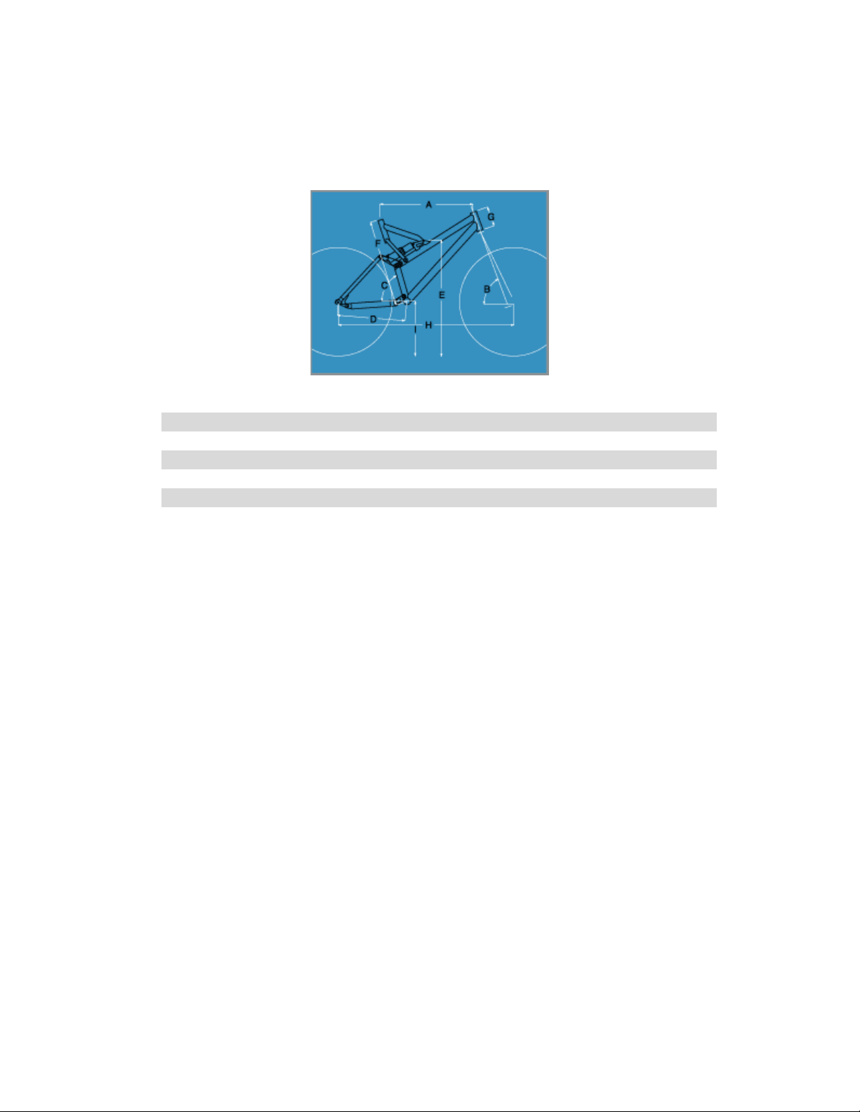
Frame Geometry
A B C D E F G H I
X-Small 21.00 70.75 73.00 16.75 26.75 19.75 3.75 40.50 13.25
Small 22.20 70.75 73.00 16.75 26.75 19.75 4.40 41.75 13.25
Medium 23.00 70.75 73.00 16.75 26.75 20.75 4.75 42.50 13.25
La ge 23.00 70.75 73.00 16.75 26.75 21.75 5.25 43.20 13.25
X-La ge 24.00 70.75 73.00 16.75 26.75 21.75 5.40 43.60 13.25
Frame Weight
Standard small frame with Fox Vanilla-R shock, 500# coil 8.5 lbs
Standard medium frame with Fox Vanilla-R , 800# coil 9.5 lbs
Quasi-Lite with Fox Float-R shock 6.75 lbs
Component Specifications
Seat-post 27.2 mm
Headset 1 1/8”
Seat-collar 34.9mm, bolt-on
Bottom Bracket 73-mm shell, 113 width for triple ring
Front Derailleur 1 3/8” ( 34.9 mm ), top-pull, top-swing
Derailleur Hanger Replacable, uses standard chainring bolt for mount
Tire learance 3” wide 26” tires should clear seat- and chain-stays
Fork ompatibility Single- or Dual- rown, 100-180mm ( 4-7” ) travel
Fork steerer length
Fork headset spacers
Shock ompatibility 7 7/8” long, 2” stroke, most types including
external-reservoir shocks
Rear Wheel Travel 4.5” (114.3mm) or 5.9” (150mm), with any shock
( two mount points )
Owners Manual
Thank you for your purchase of the Titus Quasi-Moto. We know you'll be very pleased with the
performance and features of your new frame. You will be even more pleased if you take the time to
read your owner's manual. The Quasi-Moto is not like any bike you've ever owned. This manual
offers important setup and maintenance tips to make your life easier.
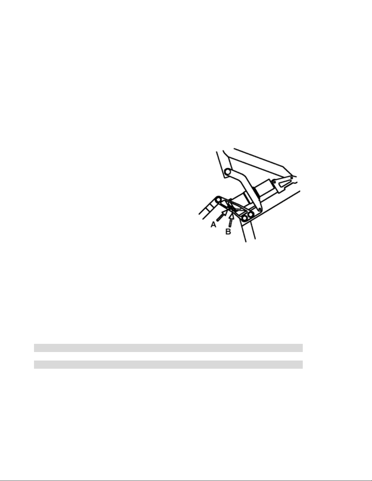
SELECTING T AVEL:
The Quasi-Moto has two rear wheel travel settings (A = 4.5" and B = 5.9"). Setting the travel affects
the head angle, seat angle, and bottom bracket height of the bike. The Quasi-Moto frame is designed
for use with a fork with at least 75mm (2.95") of travel.
•If you a e using a fo k with 80-92mm (3.1" - 3.6")
of t avel, we ecommend setting the ea of the
bike at 4.5" (Position A). This will maintain
p ope geomet y fo agg essive c oss-
count y/all-te ain iding.
•If you a e unning a fo k with 100-125mm (4" -
4.5") of t avel, we ecommend setting the ea of
the bike at 5.9" (Position B). This will set the
geomet y fo gene al all-te ain and downhill
iding.
•If you a e unning a fo k with mo e than 127mm
(5”) of t avel, then set the f ame at 5.9” (Position
B). This will p ovide you with the optimum
geomet y fo a downhill-only ace .
Your frame has come preset in the long travel mode (5.9" - Position B). To change the travel, loosen
the rear shock bolt using a 6mm allen. Remove the bolt and slide the shock eyelet in line with the
other hole. Re-insert the bolt and tighten.
WARNING: DO NOT PUSH OR SIT ON THE BIKE IF THE SHO K BOLTS ARE NOT TIGHT!
Below is a geometry chart showing the head angle, seat angle, and bottom bracket height for the
different fork and travel combinations described above.
Travel Mode Fork Travel Head Angle Seat Angle BB Height
4.5” 75mm 71 73 12.5”
5.75” 110mm 69.5 72 13.25”
5.75” 150mm 68 70 13.8”
SETTING SAG/AI P ESSU E AND SP ING ATE:
Whether you are running an air shock or coil-over shock on your Quasi-Moto, it is important to have
the suspension compress slightly (sag) when sitting on the bike. Setting the proper amount of sag will
allow the bike to follow the terrain better and maintain proper frame angles. The proper sag setting
also determines the air pressure or spring rate so that major adjustments will not be required on the
trail.

If you are using an air shock, follow the steps outlined below:
1. Place a zip tie around the shock shaft (your shock may already have an o-ring).
2. Slide the tie or o-ring up to the base of the shock body.
3. Sit on the bike with your full weight on the saddle.
4. Look down and make sure the tie is still against the shock body, and then slowly step off the
bike.
5. Measure the distance between the shock body and the zip tie/o-ring. The proper measurement
should be between 3/8 and 1/2 inch (9.5 - 12.5mm).
6. Adjust pressure up or down accordingly. Only use a rear shock specific pump, such as those
offered by Fox or Risse.
7. Recheck your settings after a few rides. The shock seals will break in and the pressure will
need to be adjusted.
For coil-over shocks, you need to follow the same basic procedure:
1. Reach between the coils and slide the bottoming bumper against the shock body.
2. Sit on the bike with your full weight on the saddle.
3. Slowly step off the bike.
4. Measure the distance between the bumper and the shock body. Like the air shock, proper sag
is 3/8 - 1/2 inch.
5. Adjust by dialing the spring preload up or down accordingly. If you are turning the preload to
the point that it becomes very difficult to turn, or backing it off far enough to release tension,
then you will need a different spring. The chart below gives a general guideline of spring rates
for different weight riders.
Suggested spring weights
Rider Weight : 110-135 lbs 130-155 lbs 160-175 lbs 170-195 lbs 190-230 lbs 225+ lbs
Spring Weight : 600 lbs 650 lbs 700 lbs 750 lbs 800 lbs 850 lbs
Note: 225+ added by empi acle data, not Titus
ADJUSTING EBOUND DAMPING:
Both the air/oil and coil-over shocks available for the Quasi-Moto have adjustable rebound damping.
Rebound damping controls the speed at which the shock returns after an impact. The amount of
damping needed will vary greatly depending on the spring weight, spring pre-load, or air pressure you
are running. The optimum situation is to have the shock rebound as quickly as possible without
bucking you off the saddle or causing the rear wheel to come off the ground. Too much rebound
damping will cause the suspension to pack up by not allowing the rear end to return quick enough for
the next bump.
To properly set the damping, dial the rebound clicker all the way in (clockwise). Next, count the
amount of clicks on your adjuster by dialing the clicker all the way out. Start with an initial setting
half way between the two. As you ride and get a feel for how the rear end is reacting, you can dial the
clicker in (more damping) or out (less damping). Adjusting two clicks at a time will make it easier to
notice the difference between the different settings. As a general rule, it will take several rides for the
seals and pivots on your frame to fully break in. New seals create more friction and will artificially
increase the amount of rebound damping. You may have to make minor adjustments and increase the

amount of rebound damping by a click or two as the
seals and pivots break in.
After you find a comfortable setting, we suggest you
write down how many clicks out the shock is set at.
It will only be a matter of time before an inquisitive
friend says, "What does this do?" as he turns your
rebound adjuster to some unknown setting.
SELECTING P OG ESSION ATE:
Your Quasi-Moto frame has two rate selections:
Position , which has a rising/falling rate curve, or
Position D, which is a full rising rate. The rate you choose will effect how plush the bike feels and
how easily the suspension moves through the travel. The two rate choices will also allow you to dial
the bike in for either an air/oil or coil-over shock.
COI -OVER: If you are using a coil-over
shock, Position D (full rising rate) will
give you a very plush, active feel with
good bottoming resistance. A coil-over
shock has a very linear spring curve. As
the spring is compressed, it does not
exponentially build up resistance to
further compression like an air shock. The
full rising rate position puts less leverage
on the shock at the end of the stroke,
resulting in a plush but progressive feel.
Placing the coil-over in Position (rising/falling rate) will result in the most active combination
possible. The ride will be super plush from beginning to end. Downhillers may want to run position D
to prevent bottoming.
AIR SHOCK: If you are using an air shock, the special air rockers will only allow you the use of
Position (rising/falling rate). This will give you the most plush, active feel. When the air shock is
compressed, the pressure inside the shock increases exponentially, making it difficult for the shock to
achieve full stroke. The failing rate portion of the suspension curve puts more leverage on the air
shock when the pressures inside the shock are highest. The result is an overall plush feel and the
ability to achieve full stroke without bottoming harshly.
TO CHANGE THE RATE:
1. Loosen and remove the pivot pin and stainless steel washers with the 5mm allen wrench.
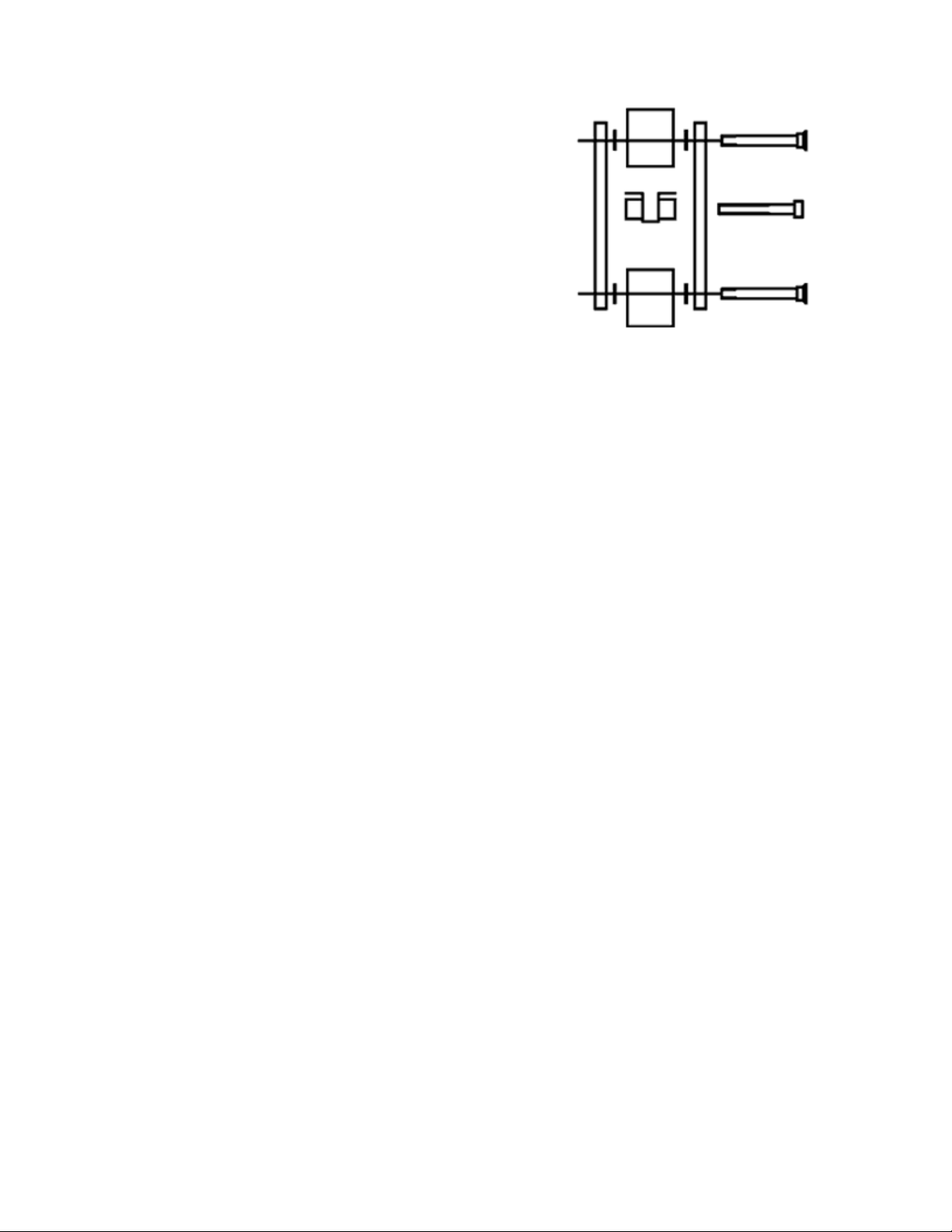
2. Slide the pin and washers over to the other hole.
See the diagram to the right for proper
orientation.
3. Tighten the 5mm pivot bolt until there is no play
in the rockers.
AUTION: Be careful not to over tighten. If the pivot
bolts are too tight, the pivots will not move freely.
MAINTENANCE AND ADJUSTMENTS:
Mountain bikes are amazing products. We know of no other off road racing machine that can put up
with the kind of abuse a mountain bike takes with relatively little service. None the less, it has once
been said, "If you take care of your equipment, your equipment will take care of you!" This is why
your Quasi-Moto frame is designed to be easy to adjust and service. We highly suggest that you take
the time to check all your equipment before every ride.
You will need the following tools:
•4, 5, 6 and 8mm allen wrenches
•10mm wrench
•rank wrench and puller
It is very important to check every nut and bolt on your frame after the first couple of rides. Bushings
and pivots will break-in and may loosen or develop play. The most important areas to check after the
first ride are the 8mm main pivot bolt and the 4mm Horst-Link bolts.
The main pivot on your Quasi-Moto uses sealed cartridge bearings and should require little or no
maintenance. The Horst pivot bushings used on your frame are very durable and do not require
constant lubrication.
If, over time, the rear end on your frame develops side play, take the following steps to track down
the reason:
1. heck your rear hub bearing adjustment and spoke tension first to make sure your rear wheel
is not the culprit.
2. Tighten the 6mm pivot bolts until there is no play in the rockers. Be careful not to over-
tighten.
3. Make sure the 4mm Horst-link bolts are tight.
4. Re-check the rear end for play. If there is still play, move on to step 7.
5. Remove drive side crank arm.
6. Tighten the 8mm pivot bolt at the lower yoke until there is no play in the lower swingarm. Be
careful not to over tighten, a 3 inch allen wrench can generate enough torque to adequately
tighten the main pivot bolt. Over-tightening may result in crushed bearings.
7. Re-check the rear end for play. If this has not solved the problem, see BEARING
REPLA EMENT.
8. Re-install drive side crank arm and Go Ride!

BUSHING SERVICE:
The life of the sealed cartridge bearings, Horst pivot bushings and linkage bushings on your Quasi-
Moto frame will vary depending on the type of conditions that you ride in and the way you ride. You
should be able to get two or more years out of your Horst pivots if you disassemble them every 6-12
months to clean and re-lube the bushings. We recommend using either Judy ButterTM, Bull Shot or
White BrothersTM fork grease when servicing your bushings.
To clean and grease your Horst pivot bushings please use the following steps:
1. Remove your rear wheel.
2. Use a 4mm allen wrench to remove the two Horst-link bolts.
3. Slide the dropouts off of the lower swingarm.
4. Remove the Horst link pivot cylinders from inside the bushings.
5. lean the bushings and pivot cylinders thoroughly. Do not use a citrus type solvent or
degreaser. WD-40 and Windex do an excellent job.
6. Lightly grease the insides and faces of the bushings.
7. Follow steps 1-4 in reverse for re-assembly. Use a generous amount of grease or Anti-Seize
(Finish Line Ti-Prep) on the 4mm allen bolts before re-assembly.
BUSHING REP ACEMENT:
To replace the pivot bushings and/or cartridge bearings, you will need the following additional tools:
•Plastic Mallet
•Blunt ended punch
•A vice, clamp or press with smooth jaws (not serrated) or a bearing kit installation tool
(available through Titus)
IMPORTANT NOTES:
•If you do not have a wealth of experience with every aspect of bicycle maintenance and repair,
we suggest going to your local shop to have a qualified mechanic replace the
bushings/bearings. Bring these instructions with you.
•When removing the bushings, extreme care must be taken not to damage the surfaces which
the bushings press into. Take your time with this project. hances are good that the bushings
will not come out easily.

To replace the 4 pivot bushings please use the following steps:
Follow steps outlined on the previous page under BUSHING SERVI E for disassembly instructions
to gain access to each set of horst link bushings.
1. Insert the blunt ended punch into the bushing
housing.
2. Line the punch up with the bushing lip.
3. Tap the punch with your mallet.
4. Tap the bushing in the + pattern (1, 2, 3 & 4) as
shown so that the bushing slides out straight.
5. ontinue in the above order until the bushing is
fully removed.
6. Repeat steps 2-6 on the remaining bushings: 4 Horst-link bushings total.
7. Lightly grease the new bushings before installation.
8. Hold the bushing housing between the vice jaws.
9. Position the new bushing against the housing, making sure that the bushing is not cocked.
Press only one bushing at a time.
10. Slowly close the vice jaws against the bushing face. Make sure that the bushing is going in
straight.
11. ontinue closing vice jaws until bushing face is flat against bushing housing.
SPECIA NOTE: A -clamp, wood clamp, hand-held
vice or similar clamping tool can be used in place of a
vice, provided that proper action is taken to ensure that
the bushing is pressed in straight and the vice face is
flat and wide enough to avoid damaging the face of the
bushing.
12. Repeat steps 8-12 for opposite bushing.
13. After the bushings have been replaced, lightly
grease the insides and faces of the bushings.
14. Follow steps outlined above under BUSHING SERVI E for re-assembly instructions.
BEARING REP ACEMENT:
The main pivot of your Quasi-Moto has been equipped with 4 sealed cartridge bearings that offer a
smooth ride and minimal maintenance. Over time, your cartridge bearings may become worn and
allow play or cause your rear end to rotate roughly. In this event, we suggest you replace your
cartridge bearings according to the following instructions:

Main Cartridge Bearing Replacement
1. Remove your rear wheel.
2. Remove the drive side crank arm.
3. Use a 4mm allen wrench to remove the two
Horst-link bolts.
4. Slide the dropouts off of the lower swingarm.
5. Remove the 8mm main pivot pin. Be ready to
catch the 2 washers as the pin is removed.
6. Remove the lower swingarm from the front
triangle.
7. Using blunt ended punch, tap out the far set of
bearings in the + pattern shown.
8. Tap the other set of bearings out of the frame, taking care not to scar the inside of the frame.
Do not attempt to re-use the bearings you've removed, even if they come out intact.
9. Apply a small amount of grease to the outside edge of the new bearings.
10. Using a vice or press, and a friend to hold your frame steady, press in the bearings one at a
time. Make sure they go in straight and that you're pressing on both the inner and outer races
evenly.
11. Install both bearings on one side of the frame.
12. Re-insert the compression sleeve inside the bearing
shell.
13. Press the second set of bearings into the frame.
14. Apply grease to the threads, shaft and head of the 8mm
pivot pin.
15. Have your friend hold the swingarm up to the front
triangle as you align the washer and insert the pin into
the drive side of the swingarm.
16. Align the washer on the non-drive side of the swingarm and slide the pin through. A gentle
tap with a rubber mallet may be necessary, but take care not to hammer the threads into the
swingarm on the other side.
17. Tighten the 8mm main pivot pin until snug. Be careful not to over tighten, a standard 3 inch
allen tool can generate enough torque to adequately tighten the main pivot bolt. Over-
tightening may result in crushed bearings.
Follow steps 1-4 in reverse for re-assembly.
ADDITIONAL WA NINGS AND EGULATIONS:
1. Mountain biking is an inherently dangerous sport. Know your limitations and ride within
them. RIDE AT YOUR OWN RISK!
2. Night riding is dangerous. Your Quasi-Moto frame is not supplied with any type of reflective
or lighting gear. WE DO NOT RE OMMEND RIDING AT NIGHT WITHOUT THE
PROPER GEAR.
3. Your Quasi-Moto frame is designed for closed course riding only. To make it street legal it is
your responsibility to acquire and install the required reflective and lighting gear outlined by
your local municipalities and federal government.
4. Your bike should be assembled only by a certified mechanic.
5. Always wear a helmet and full protective gear while riding.

Hardware Specifications
What Spec Source
Shock rear eyelet bolt (1x) M8-1.25x60 socket cap ss Austin Bolt o.
Shock front eyelet bolt (1x) Same as seat-tower front bolt ditto
Shock rear hardware hardware M8 x 43mm overall width Universal ycles
Shock front mount hardware M6 x 15mm overall width Universal ycles
Rear linkage plate bolt (4x) M8-1.25x20 button socket cap ss Austin Bolt o.
Rear linkage plate spacers (4x) 8x15x3/5 mm ( IDxODxW ) alu ustom?
Seat tower rear bolt (1x) M6-1.0x65 socket cap ss Austin Bolt o.
Seat tower front bolt (2x) M6-1.0x45 socket cap ss Austin Bolt o.
Seat tower bolt (3x) M6-1.0 nylon insert L/N ss Austin Bolt o.
hainstay horst-link bolt (2x) M6-1.0x25 flat socket cap sc. ss Austin Bolt o.
hainstay main-pivot bolt (1x) ustom? Titus?
hainstay horst-link bushing (2x) ustom? Titus?
hainstay main-pivot bearings (4x) Type 6802 2RS or H 6802 LLB Enduro Fork Seals
hainstay main-pivot inner spacer (1x) ustom? Titus?
hainstay main-pivot outer spacers (2x) ustom? Titus?
Swing-link pivot bearings (4x) Type 6809 ( enduro ) Enduro Fork Seals
Seat-collar bolt (1x)
Disc-brake mount bolt (6x) M6-1.5x25 socket cap ss (unverified) Austin Bolt o.
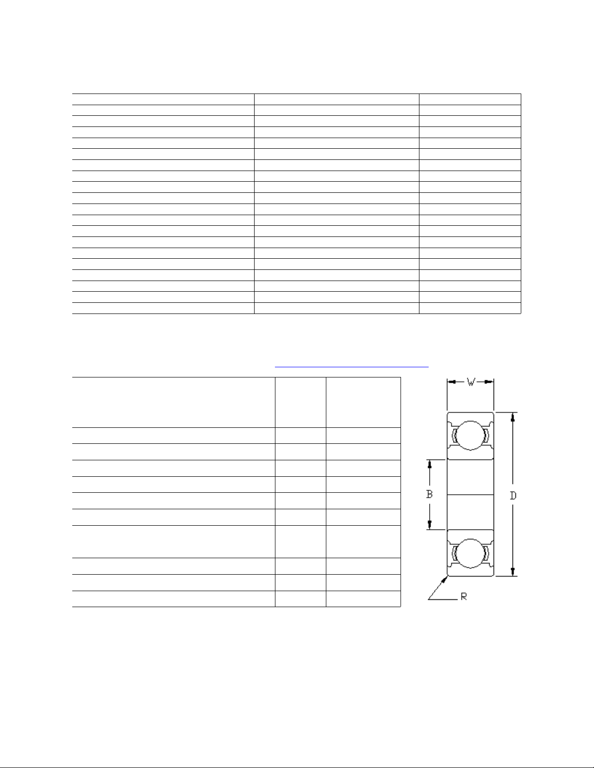
Bearing Specifications
[ Reproduced from the IKS web site www.iskbearing.com/68000_Series_ atalog.htm ]
Type Bore Diameter
(mm)
B
Outer Diameter
(mm)
D
Width
(mm)
W
Fillet adius
(mm)
6800 10 19 5 0.5
6801 12 21 5 0.5
6802 15 24 5 0.5
6803 17 26 5 0.5
6804 20 32 7 0.5
6805 25 37 7 0.5
6806 30 42 7 0.5
6807 35 47 7 0.5
6808 40 52 7 0.5
6809 45 58 7 0.5
6810 50 65 7 0.5
Bearing Type Use on the Quasi-Moto
6802: Main pivot bearings (4 ea)
6809: Swing-link pivot bearings (4 ea)
Table of contents


