manuals.online logo
Brands
  1. Home
  2. •
  3. Brands
  4. •
  5. Yeti
  6. •
  7. Bicycle
  8. •
  9. Yeti KoKoPelli User manual

Yeti KoKoPelli User manual

YETI CYCLES
600 Corporate Circle, Unit D
Golden, CO
USA
p.303-278-6909 / 888-576-9384
www.yeticycles.com
Table of Contents
Brand Overview 6
Maintenance Schedule 8
Assembly Overview 10
Assemblyū12
Exploded Views 20
Part List 22
Warranty 26
Contact Information 27
6
OVERVIEW
Overview
Warning: Make sure you review and understand the warnings, instructions and content of this manual and
accompanying manuals for your bicycle.
Warning: Technological advances have made bicycles and bicycle components more complex and the pace of
innovation is increasing. It is impossible for this manual or accompanying manuals to provide all the information
required to properly repair and maintain your bicycle. In order to help minimize the changes of injury, it is critical for you
to have work performed by an authorized Yeti dealer.
performed by an authorized Yeti dealer.
This manual contains many “Warnings”
and “Cautions” concerning the consequences of
failure to maintain or inspect your bicycle. The
combination of the safety alert symbol and the word
“Warning” indicates a potentially hazardous situation
in which, if not avoided, could result in serious injury
or death. The combination of the safety alert symbol
and the word “Caution” indicates a potentially
hazardous situation in which, if not avoided, may
result in minor injuries or damage to your bicycle
or a component of your bicycle. Be sure to read and
understand all “Warnings” and “Cautions”.
Congratulations on your purchase of a new
Yeti bicycle.We are confident your new bicycle will
exceed your expectations for value, performance and
ride quality. Each frameset and component has
been custom specified and designed to enhance your
riding experience. Whether you are a beginner
cyclist or a seasoned-pro, Yeti bicycles will provide
endless hours of two-wheeled fun.
General infOrmatiOn
This model-specific manual is designed to be
used in conjunction with the general Yeti Owner’s
Manual and the manuals supplied by the suspension
manufacturers. If you did not receive the Yeti
Owner’s Manual or the manual provided by the
suspension manufacturer, download the materials
off the Internet, or contact you dealer.
Bicycling can be a hazardous activity
even under the best of circumstances. Proper
maintenance of your bicycle is your responsibility
and when done properly helps reduce the risk of
injury and damage to your bicycle. This manual
outlines basic setup and maintenance
recommendations of your new Yeti. Because it is
impossible to anticipate every situation or condition
that may occur during the assembly, setup and
maintenance of your bicycle, Yeti recommends that
all service and repairs be
8
Maintenance
MAINTENANCE
MAINTENANCE Following these guidelines will help maintain the performance of your bicycle and prevent
more serious problems from arising. It is important to remember that service intervals can vary depending
on climate, trail conditions and riding frequency.
Caution: The torque specications listed should be used as a guide when performing maintenance. Technological
advances have made bicycles and bicycle components more complex, and the pace of innovation is increasing.
Because of these advances, Yeti recommends that you refer to the torque specications of the manufacture’s component
you are adjusting. In order to help minimize the chances of injury, do not perform any maintenance that you are no
condent can be completed within your abilities.
MAINTENANCE? If you are having trouble with any of the
maintenance tasks that need to be performed contact your
local dealer or visit www.parktool.com and check out the
repair help section. This section contains detailed instruction
on many of the service items listed in the maintenance
schedule.
TORQUE We have attached a brief list of torque specifications for bolts and components that may need to
be tightened while performing basic maintenance. This is just a guide. For specific torque, specifications,
please contact the component manufacturer directly.
TORQUE SPECS
Pivot Bolts 125 -150
Derailleur Hanger Bolts 30 -45
Handlebar Binder Bolt 150 -180
Stem Binder Bolt 175 -260
Seatpost Binder Bolt 150 -180
Saddle Clamp Bolts 175 -250
Rear Derailleur 70 -86
Front Derailleur Clamp 45 -60
Chainring Bolts 88 -132
ACTION WEEKLY MONTHLY 3 MONTHS ANNUALLY
Clean and lube chain x
Check tire pressure x
Clean bike of mud and debris (never
spray water directly into frame or
components)
x
Check brake function x
Check shock pressure, if applicable x
Check for loose bolts and tighten, if
necessary
x
Check headset and tighten / loosen, if
necessary
x
Thoroughly clean pivot points with a
rag (do not lubricate)
x
Replace brake pads, if necessary x
Check tires for wear x
Check spoke tension and retention, if
necessary
x
Check chain for worn, damaged, or
loose links, replace chain if necessary
x
Complete tune-up performed by an
authorized Yeti dealer
x
10
Assembly
ASSEMBLY
TOOLS NEEDED
Warning: Service on Yeti bicycles requires special
knowledge and tools. Yeti Cycles recommends that all
service and repairs be performed by an authorized Yeti
dealer.
Rubber Mallet
Two- 5mm allen keys
8mm allen key
Arbor press or vice w/
aluminum jaws
Lock-tite thread lock
Range of sockets
YETI TIPS
Make sure your tools are in good condition. A
worn allen key can round the hex on a bolt
preventing proper torque. Be careful when using
ballpoint allen wrenches for the same reason.
Torque settings are listed throughout the
instructions. It is also important to prep all bolt
threads. The instructions denote whether to use
a blue Loctite compound or grease.
The linkage tool is necessary to properly
disassemble and reassemble the linkage. Using
a hammer to tap out the pin can cause damage
to the linkage and shock.
Not every tool may be needed for the assembly /
disassembly of your bike. The list encompasses
all the tools necessary to completely assemble
and disassemble a each bike.
12
ASSEMBLY
Assembly
ASSEMBLY
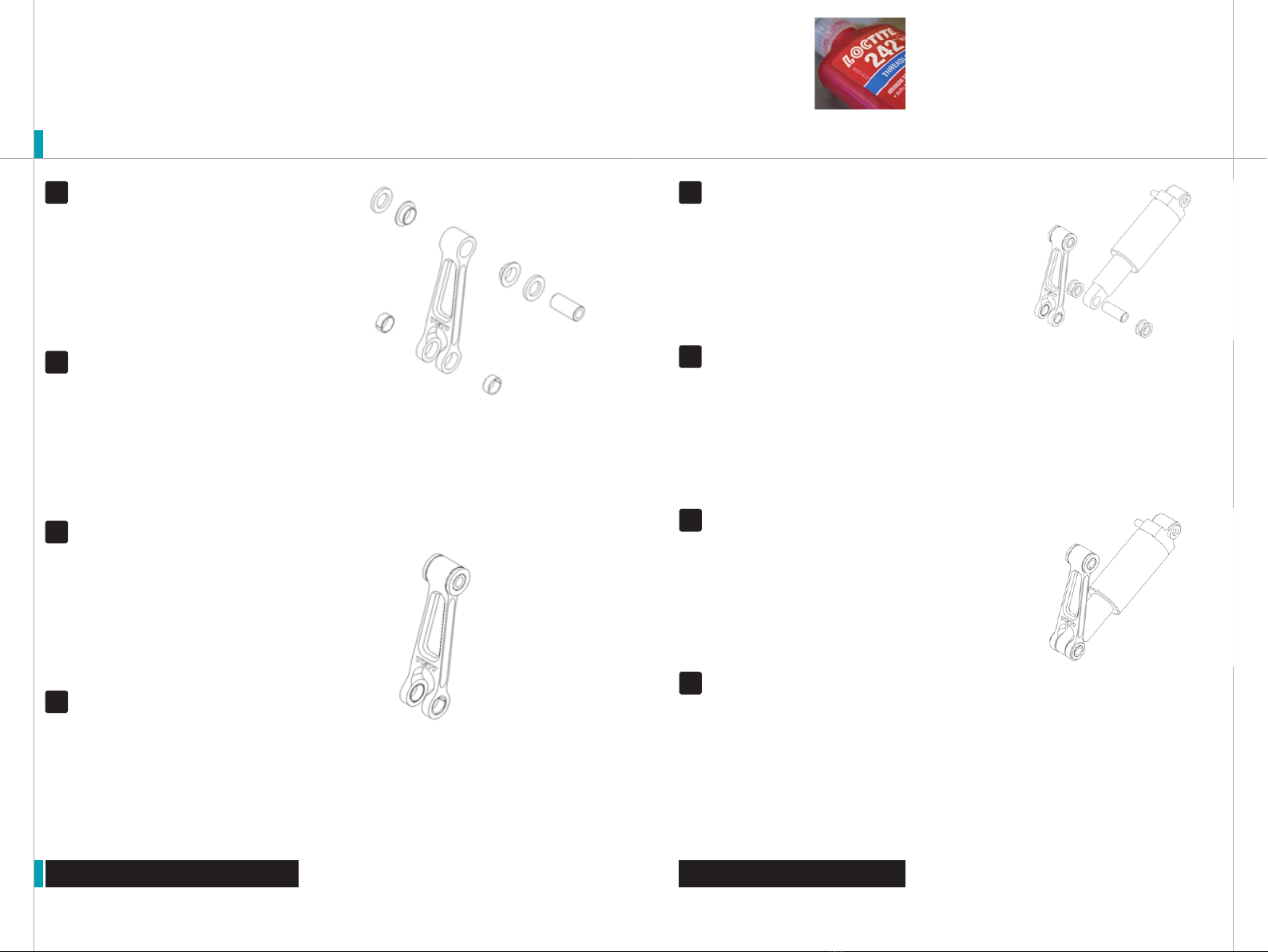
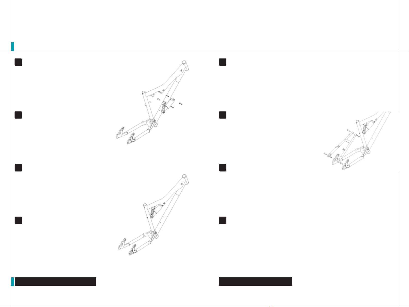
DOGBONE ASSEMBLY Press the two 1/4’’ long
Garlock bushings (9) into each side of the bottom end
of the dogbone (2). Ensure that the dogbone (2) bosses are
supported as the bushings (9) are pressed into place. The
Garlock bushings (9) should be pressed in level and flush
with the outside faces, as shown in Figure 2b.
DOGBONE ASSEMBLY Press the dogbone bushing
insert (8) into the Igus bushings (22) until there is equal
amount of insert sticking out each side of the Igus bushings
(22).
DOGBONE ASSEMBLY Place dogbone bushing spacers
(21) on each side of exposed dogbone bushing insert (8).
DOGBONE ASSEMBLY Install the two Igus bushings (22)
into the 15mm bore at the top part of the dogbone by
pressing the bushings level into the bore. The bushings (22)
should be pressed into the bore until the flanges are flush
with the bore face, as shown in Figure 2b.
Figure 2a: Dogbone (2) with bushings (22 &
9) and insert (8), exploded
Figure 2b: Dogbone (2) with
bushings (22 & 9) and insert (8),
assembled
SHOCK ATTACHMENT While holding the black nylon
washer (11) to the dogbone (2), place the slider end of
the Fox shock (2) between the two bosses of the dogbone (2).
Line up the bushing bore in the Fox shock (3) with the Fox pin
(10) already pressed into the dogbone (2).
6
SHOCK ATTACHMENT Press the 1.3’’ Fox Pin (10)
into an installed Garlock bushing (9) at one end of the
dogbone. The pin should be all the way through one of the
bosses on one side with about 1/16th of an inch of the pin
(10) exposed on the inboard side. Place black nylon washer
(11) on the exposed inboard Fox pin (10) and hold in place by
hand.
5
SHOCK ATTACHMENT After lining up the Fox shock (3)
with the Fox pin (10), press the Fox pin (10) further into
the dogbone (2) and into the Fox shock (3) until the pin just
meet flush with the other side of the Fox shock (2) bushing
bore. This should leave about 1/16th of an inch gap between
the shock (2) and the boss on the other side of the dogbone.
Insert a black nylon washer (11) within the 1/16th’’ gap and
center as close as possible with a screwdriver.
7
SHOCK ATTACHMENT Press the Fox pin (10) the rest of
the way through the shock (3) and into the other side of
the dogbone (2) boss. Press the pin (10) in until it is centered
in the assembly. This will leave about 1/6th’’ exposed on each
side of the dogbone (2) as seen in Figure 3b. Place a black
nylon washer (11) on each end of the exposed Fox pin (10).
These washers (10) will have to be held in place by hand in
one of the following procedures.
8
THREAD PREP Yeti recommends prepping all bolt threads
at once on your work bench with Loctite or grease. This will
ensure that all bolts are used in assembly. The medium
strength (blue) Loctite formula along with proper torque is
ideal to keep the bolts snug.
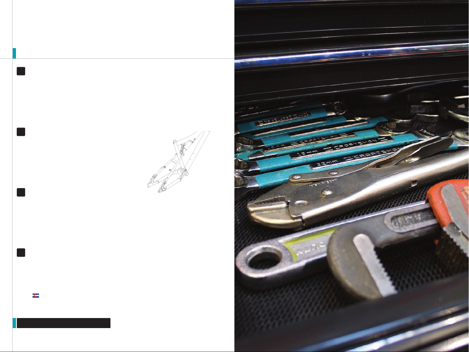
Figure 3a: Dogbone (2) and Shock (3)
Assembly with Fox Pin (10) and Black
Nylon Washers (11), exploded
Figure 3b: Dogbone (2) and Shock (3)
Assembly with Fox Pin (10) and Black
Nylon Washers (11), assembled
1
3
2
4
14
ASSEMBLY
Assembly cont.
ASSEMBLY
CHAINSTAY ASSEMBLY Next, install the sealed
bearings (7) into the chainstay (5) main pivot bore. Press
them into each side of from the outside until they bottom out
on the internal lip
CHAINSTAY ASSEMBLY After all four Igus bushings
are pressed into place, install the rear bushing inserts
(23) into the bushing (22) bores so that the rear insert (23)
end faces are flush with the outside exposed face of the Igus
bushings (22).
CHAINSTAY ASSEMBLY Begin with pressing the Igus
bushings (22) into the rear dropout pivot holes. These
bushings are pressed in the same as the Igus bushings (22)
are pressed into the dogbone (2). Press an Igus bushing (22)
into each side of the chainstay (5) dropout while supporting
the other side
Figure 4a: Chainstay (5) assemble with main
pivot bearings (7), rear pivot bushings (22)
and rear bushing inserts (23), exploded
Figure 4b: Chainstay (5) assembled
with main pivot bearings (7), rear pivot
bushings (22) and rear bushing inserts(23),
assembled
CHAINSTAY ATTACHMENT Place thrust washers (13)
over installed bearing inserts (6) and hole into place.
With the front triangle (1) firmly held in place and the inserts
(6) and washers (13) installed, slide chainstay (5) main pivot
over front triangle (1) main pivot. You will have to hold the
thrust washers (13) as you do this. This fit will be right and
may require the installer to work the chainstay (5) side to
side while trying to work onto frame (1) pivot.
13
CHAINSTAY ATTACHMENT Place front triangle in bike
stand or something similar to hold it in place. Install
bearing inserts (6) into the main pivot. First assembly may
require main pivot holes to be reamed.
12
CHAINSTAY ATTACHMENT Once the chainstay (5) is on
the main pivot, center as close as possible the main
pivot bearing (7) with the bore through the main pivot of the
front triangle (1). When holes are aligned as concentric as
possible, insert the main pivot pin (16) into the right side
main pivot bearing (7). Tap into place with a hammer until the
pin is pushed at least part way through the other side of the
main pivot bearing (7).
14
CHAINSTAY ATTACHMENT Place a little Loc-tite on the
thread of two button head bolts (19). Place washers
(12) on the button heads (19) and thread them into the main
pivot. While holding one side with a 5mm allen key, tighten to
100 - 125 in/lbs.
15
Figure 5a: Chainstay (5) and ASR Front
Triangle (1) with main bearings (7), button
head bolts (19), and flat washers (12),
exploded
Figure 5b: Chainstay (5) and ASR Front
Triangle (1) with main bearings (7), button
head bolts (19), and flat washers (12,
assembled
9
11
10
Titlenames
16
ASSEMBLY
Assembly cont.
ASSEMBLY
DOGBONE ATTACHMENT Put a dab of Loc-tite onto
threads of a Yeti shoulder bolt (20). Thread bolt (20) and
washer (14) into other side of knuckle and tighten to 155 in/
lbs with a 5mm allen key. Use a second 5mm allen key to
hold the sleeve bolt (17) if necessary.
17
DOGBONE ATTACHMENT Slide air-valve end of shock
(3) into front triangle (1) knuckle pocket and line up
8mm bolt holes. Insert a 24.8mm sleeve bolt (17) into knuckle
from the left side of the bike and thru the shock (3) hole to
the other side of the knuckle.
16
DOGBONE ATTACHMENT With the insert (8) flush into
the other end of the dogbone (2), slide the dogbone (2)
between the front triangle (1) dogbone brackets mounted to
the top tube and line up the 8mm bolt holes while holding
spacers (21) in place. Insert a 24,8mm sleeve bolt (17)
into the bracket from the left side of the bike and thru the
dogbone insert (8) to the other side of the bracket.
18
CHAINSTAY ATTACHMENT Put a dab of Loc-tite onto
threads of a Yeti shoulder bolt (20). Thread bolt (20)
and washer (14) into other side of bracket and tighten to 115
in/lbs with a 5mm allen key. Use a second 5mm allen key
to hold the sleeve bolt (17) if necessary. If the black nylon
washers (11) have fallen off the Fox pin (10), then put them
back into place in preparation for installing the seatstay (4).
19
Figure 6a: Dogbone-shock (2-3) assembly
mounted to front triangle (1), exploded
Figure 6b: Dogbone-shock (2-3) assembly
mounted to front triangle (1), assembled
FINAL ASSEMBLY While holding the black nylon
washers (11) in place, slide the upper seatstay (4) over
the washers (11) onto the Fox pin (10). This fit may be tight
and require that the seatstay (4) be worked back and forth to
get over the washers (11) and onto the Fox pin (10).
21
FINAL ASSEMBLY Begin by attaching upper seatstay
(4) to the dogbone-shock (2-3). First, ensure the black
plastic washers (11) are placed on the ends of the Fox pin
(10). The washers (11) will have to be held in place by hand
when installing this part of the seatstay (4).
20
FINAL ASSEMBLY Once onto the Fox pin (10), center
the 8mm thru holes and slide a 35.5mm Yeti sleeve bolt
(18) from the left side, thru the left side of the upper seatstay
(4), thru the Fox pin (10), and into the right side of the upper
seatstay (4).
22
FINAL ASSEMBLY Put a dab of Loc-tite onto the
threads of a Yeti shoulder bolt (20) and insert the bolt
(20) and washer (14) into bolt (18) and tighten to 115 in/lbs
with a 5mm allen key. Use a second 5mm allen key to hold
the sleeve bolt (17) if necessary.
23
Figure 7a: Attached seatstay (4) to front
triangle (1), exploded
Titlenames
18
ASSEMBLY
Assembly cont.
FINAL ASSEMBLY One side at a time, slide each lower
seat stay (4) clevis over the rear Igus bushings (22) and
rear bushing inserts (23). Once you have each side in place,
center the 8mm thru holes simultaneously. From one of the
inboard sides of the seat stay (4) insert a 21mm sleeve bolt
(15) thru the seatstay (4), thru the rear bushing insert (23),
and into the other side of the seatstay (4).
25
FINAL ASSEMBLY Next, install the lower portion
of the seat stay (4) onto the chainstay (5). Begin by
ensuring the rear bushing inserts (23) are place flush into the
chainstay (5) rear Igus bushings (22).
24
FINAL ASSEMBLY Put a dab of Loc-tite onto the threads
of a button head (19) and insert the button head (19) and
washer (12) into the outboard side of the lower seat stay (4).
Thread button head (19) and washer (12) into bolt and tighten
to 115 in/lbs with a 5mm allen key. Use a second 5mm allen
key to hold the sleeve bolt (17) if necessary. Repeat process
for other side of seat stay (4).
26
FINAL ASSEMBLY At this point, the frame is fully
assembled and ready for component assembly or
packing. As a final check make sure all bolts are tight, brakes
stud are tights set clamp is installed, and all parts fit without
abnormal interference, and the head badge is tightly in place.
Also look down the plane of the frame to check alignment.
The seat stays should be spaced evenly around the seat
tube. The shock and dogbone must be in-place with the front
triangle.
27
Figure 7a: Attached seatstay (4) to front
triangle (1), assembled
20
Exploded Views
EXPLODED VIEWS
REBUILD KITS The individual components of each Yeti bike
are not sold separately. All yeti parts are sold in rebuild kits
listed below. Each and every part can be obtained by purchas-
ing one of the rebuild kits. Cross reference the part number
you desire from the parts list to the rebuild list.
PARTS LIST
QTY. PART # DESCRIPTION
1 1 NA Front Triangle
2 1 500070023 Yeti Aluminum Dogbone
3 2 100040032 Fox Float RL Shock
4 1 500070025 Welded Seatstay Assembly
5 1 500070024 Welded Chainstay Assembly
6 2 300030082 Main Pivot Aluminum Bearing Insert
7 2 300020024 Sealed Main Pivot Bearing- R62RS Max
8 1 300020022 Anodozied Insert at Dogbone
9 2 300020017 Garlock 08DP04 Steel Backed Bushing
10 1 100040032 Rear Shock Pivot Pin Thru Shock/Dogbone
11 4 300030052 Black Spacer .75 OD x .5 ID x .061 Thick
12 4 300030062 12.5mm ID x .5mm Thick Washer, Pivots
13 2 300030084 Main Pivot Spacer, 1.25’’ OD x 1’’ ID x .062 Thick
14 3 300030069 12.5mm OD x 8.5mm ID x .6mm, Yeti Shoulder Bolts
15 2 300030005 21mm Button Head Sleeve Pivot Bolt
16 1 300030083 .375’’ Main Pivot Pin, Stainless Steel
17 2 300030077 24.8mm Yeti Sleeve Bolt, 5mm Allen Key
18 1 300030076 35.5mm Yeti Sleeve Bolt, 5mm Allen Key
19 4 300030006 M6 x 1 x 12 Button Head, 5mm Hex
20 3 300030078 Yeti Shoulder Bolt, 5mm Allen
21 2 300030081 Delrin Bushing Spacer
22 6 300020016 Pivot Bushings, IGUS P/N LFM-1315-06
23 2 300020014 Rear Pivot Bushing Insert
22
Parts List
PARTS LIST
PART NUMBER DESCRIPTION QTy.
200020076 KOKO ‘01-’03 PROGRESSIVE HARD 5TH MOUNTING HARDWARE 1
300030098 ALUMINUM SLEEVE INSERT FOR KOKO MODEL 1
300030099 ALUMINUM HAT FOR KOKO MODEL 2
300030069 WASHER SS 8.5MM ID 12.5MM OD 2
300030078 PIVOT BOLT MALE YETI 17MM CHROMEMOLY 2
300030091 PIN- PROGRESSIVE AIR SHOCK 1
300030093 HAT-0-RING-OIN PROGRESSIVE AIR SHOCK 2
300030094 0-RING PROGRESSIVE AIR SHOCK 2
20002077 KOKO ‘01-’03 FOX MOUNTING HARDWARE 1
300030069 WASHER SS 8.5MM ID 12.5MM OD 2
300030076 PIVOT BOLT FEMALE YETI 35.5MM CHROMEMOLY 1
300030078 PIVOT BOLT MALE YETI 17MMCHROMEMOLY 1
300030086 PIN-STEEL SHOCK- 1.30 ASR/K 1
300030100 WASHER-BLK NYL .70 X .51 X .061 4
200020078 KOK ‘02-’03 MASTER REBUILD MAIN PIVOT BEARING MODEL 1
300030062 WASHER SS 6.5MM ID 12.5 OD .5M 2
300030100 WASHER-BLK NYL .70 X .51 X .061 6
300030086 PIN - STEEL SHOCK - 1.30 ASR/K 1
300030077 PIVOT BOLT FEMALE YETI 24.8MM CHROMEMOLY 2
300030084 WASHER - KOKO/ASR MAIN PIVOT PIN 2
300030083 PIN - MAIN BEARING - KOKO/ASR 1
300030082 BUSHING - MAIN PIVOT SHAFT INS 2
300030081 WASHER DELRIN .52ID X .849 OD X .10 2
300030069 WASHER SS 8.5MM ID 12.5MM OD 10
300030076 PIVOT BOLT FEMALE YETI 35.5MM CHROMEMOLY 1
300030006 BOLT-BUTTON HD M6 X 1 X 12 5 MM HEX 4
300030005 BOLT - PIVOT - 7.95 X 20MM 2
300020024 BEARING R62RSMAX MAIN PIVOT KOKO 2
300020022 SLEEVE-INNER BUSHING- DOGBONE KOKO/ASX 1
300020017 GARLOCK BUSHING .5’’X.25’’ 08 DP0 2
300020016 BUSHING - IGUS - ASR 6
300020014 SLEEVE-INNER BUSHING - CLEVIS - AS 2
300030078 PIVOT BOLT MALE YETI 17MM CHROMEMOLY 3
200020079 KOKO ‘01-’02 MASTER REBUILD MAIN PIVOT BUSHING MODEL 1
300030082 BUSHING - MAIN PIVOT SHAFT INS 2
PART NUMBER DESCRIPTION QTy.
300020011 BUSHING - TERCITE X- .750ID- ASR 2
300020014 SLEEVE-INNER BUSHING- CLEVIS- AS 2
300020016 BUSHING - IGUS - ASR 6
300020017 GARLOCK BUSHING .5’’ X .25’’ 08DPO 2
300020022 SLEEVE-INNER BUSHING- DOGBONE KOKO/ASX 1
300030005 BOLT-PIVOT - 7.95 X 20MM 2
300030006 BOLT - BUTTON HEAD M6 X 1 X 12MM HEX 4
300030054 BOLT CAP M6 X 1 X 40-ASR 1
300030069 WASHER SS 8.5MM ID 12.5MM OD 10
300030072 PIVOT BOLT FEMALE YETI 24.8MM CHROMEMOLY 2
300030077 PIVOT BOLT FEMALE YETI 24.8MM CHROMEMOLY 2
300030081 WASHER DELRIN .52ID X .849OD X.10 2
300030086 PIN - STEEL SHOCK - 1.30 ASR/K 1
300030100 WASHER- BLK NYL .70 X .51 X .061 6
300060030 INSERTS- BUSHING- THREADED ASR 1
300060031 INSERTS- BUSHING- NON-THREADED ASR 1
300030076 PIVOT BOLT FEMALE YETI 35.5MM CHROMEMOLY 1
300030078 PIVOT BOLT MALE YETI 17MM CHROMEMOLY 3
200020084 KOKO ‘02-’03 BEARING / BUSHING REBUILD KIT 1
300020014 SLEEVE-INNER BUSHING - CLEVIS- AS 2
300030100 WASHER-BLK NYL .70 X .51 X .061 6
300030084 WASHER - KOK/ASR MAIN PIVOT PIN 2
300030083 PIN - MAIN BEARING - KOK-ASR 1
300030082 BUSHING - MAIN PIVOT SHAFT INS 2
300030006 BOLT- BUTTON HEAD M6 X 1 X 12 5MM HEX 2
300020024 BEARING R62RSMAX MAIN PIVOT KOKO 2
300020022 SLEEVE-INNER BUSHING- DOGBONE KOKO/ASX 1
300020017 GARLOCK BUSHING .5’’ X .25’’ 08DP0 2
300020016 BUSHING - IGUS- ASR 6
200020085 KOKO ‘01-’02 BUSHING REBUILD KIT MAIN PIVOT 1
300060020 INSERTS- BUSHING- THREADED - ASR 1
300030100 WASHER- BLK NYL .70 X .51 X .061 6
300030072 WASHER SS 6MM ID 9MM OD 1MM TH 1
300030054 BOLT CAP M6 X 1 X 40 - ASR 1
300020022 SLEEVE - INNER BUSHING - DOGBONE KOKO/ASX 1
24
PARTS LIST
Parts List
300020017 GARLOCK BUSHING .5’’ X .25’’ 08DP0 2
300020016 BUSHING - IGUS - ASR 6
300020014 SLEEVE - INNER BUSHING - CLEVIS - AS 6
300020011 BUSHING - TERCITE X - .750 ID - ASR 2
300060031 INSERTS - BUSHING - NON-THREADED ASR 1
500050015 ASR / KOKO CHAINSTAY W/ BEARINGS 1
300020024 BEARING R62RS MAX MAIN PIVOT KOKO 2
500070024 CHAINSTAY - ASR / KOKO PAINTED 1
500060001 ASR / KOK0 DOGBONE KIT ‘00 - ‘02 1
300020017 GARLOCK BUSHING .5’’ X .25’’ 08DP0 2
500070023 ASR/KOKO DOGBONE POLISHED 1
300020013 SLEEVE - INNER BUSHING - DOGBONE ‘00-’02 ASR 1
300020016 BUSHING - IGUS - ASR 2
PART NUMBER DESCRIPTION QTy.
26
Warranty
WARRANTY
YETI LIMITED (2) TWO YEAR FRAME WARRANTY (applies to 303, 4X, DJ)
Yeti Cycles will repair or replace, at its option, any frame it determines to be defective materials and / or
workmanship. The (2) two year limited warranty is conditioned upon the bicycle being ridden under normal
conditions and having been properly maintained. This warranty does not apply to the components attached
to the frameset such as suspension components, wheels, drive train, brakes, seatpost, handlebar and stem.
This warranty applies only to the original owner and is non-transferable. This warranty is void if the bicycle
was not properly assembled by an authorized Yeti dealer.
YETI LIMITED (5) FIVE YEAR FRAME WARRANTY (applies to AS-R sl, AS-R Carbon, 575, ARC, ARC-X)
Yeti Cycles will repair or replace, at its option, any frame it determines to be defective materials and / or
workmanship. The (5) five year limited warranty is conditioned upon the bicycle being ridden under normal
conditions and having been properly maintained. This warranty does not apply to the components attached
to the frameset such as suspension components, wheels, drive train, brakes, seatpost, handlebar and stem.
This warranty applies only to the original owner and is non-transferable. This warranty is void if the bicycle
was not properly assembled by an authorized Yeti dealer.
ADDITIONAL CONDITIONS
These limited warranties do not apply to normal wear and tear, nor to claimed defects, malfunction or
failures that result from abuse, neglect, improper assembly, improper maintenance, alteration, collision,
crash or misuse. The original owner shall pay all labor charges connected with the repair or removal of all
components. Under no circumstances does this limited warranty include of the cost of travel or shipment to
and from an authorized Yeti dealer. In order to exercise your rights under these limited warranties, the bicycle
or frameset must be presented to an authorized Yeti dealer, together with proof of purchase.
The above warranties have been in effect since January 2000. All Yeti frames sold prior to that dateū
had a limited (1) one year warranty on the frameset.
No Fault Replacement Policyū
Yeti Cycles will make replacement parts available at a minimum charge to the original owner in theū
event of a crash or any other non-warranty situation. Yeti Cycles does this at its sole discretion and
reserves the right to refuse this offer.
If you have a warranty concern, please contact your authorized Yeti dealer.ū
NO FAULT REPLACEMENT POLICY
Yeti Cycles will make replacement parts available at a minimum charge to the original owner in the event of a
crash or any other non-warranty situation. Yeti Cycles does this at its sole discretion and reserve the right to
refuse this offer. If you have a warranty concern, please contact you authorized Yeti dealer.
PRODUCT LIFE CYCLE
Every Yeti frameset has a useful product life cycle. The length of that useful product life cycle will vary
depending on the construction and materials of the frameset, maintenance and care the frameset receives,
and the amount and type of use the frameset is subjected to over its life. Yeti recommends that an authorized
Yeti dealer should inspect the frame for stress annually. Frame stress could cause potential failure and the
signs are usually apparent in the form of cracks, fracture lines, deformation, dents and other visual indicators
of abnormality. These safety checks for frame stress are important to prevent accidents, injury to the cyclist
and product failure of a Yeti frameset.
DISCLAIMER
Yeti Cycles is not responsible for any damages to you or others arising from riding, transporting or other
use of your bicycle. In the event that your frame breaks or malfunctions, Yeti Cycles shall have no liability or
obligation beyond the repair or replacement of your frame pursuant to the terms outline in this warranty.
CONTACT INFO
Yeti Cycles
600 Corporate Circle, Unit D
Golden, CO 80401
(p) 303-278-6909
(f) 303-278-6906
WWW.YETICYCLES.COM
BUSINESS HOURS
Monday-Friday
8AM-11:30AM, 1:00PM-5:30PM
(Mountain Time)

Other Yeti Bicycle manuals

Yeti 575 2012 User manual

Yeti

Yeti 575 2012 User manual

Yeti AS-X User manual

Yeti

Yeti AS-X User manual

Yeti ARC User manual

Yeti

Yeti ARC User manual

Yeti 575 '08-'09 User manual

Yeti

Yeti 575 '08-'09 User manual

Yeti 160E User manual

Yeti

Yeti 160E User manual

Yeti SB130 User manual

Yeti

Yeti SB130 User manual

Yeti EP801 User manual

Yeti

Yeti EP801 User manual

Yeti SB66 C User manual

Yeti

Yeti SB66 C User manual

Yeti AS-Rsl User manual

Yeti

Yeti AS-Rsl User manual

Yeti 2011 ARC-X User manual

Yeti

Yeti 2011 ARC-X User manual

Yeti 303 DH User manual

Yeti

Yeti 303 DH User manual

Popular Bicycle manuals by other brands

Quantum BROADWAY manual

Quantum

Quantum BROADWAY manual

Edbikes 26" City Bike owner's manual

Edbikes

Edbikes 26" City Bike owner's manual

Mark2 E-Motion CRUISER user manual

Mark2

Mark2 E-Motion CRUISER user manual

Cyrusher FR100 Installation instruction

Cyrusher

Cyrusher FR100 Installation instruction

Sportplus SP-DB-1100-B-i Instructions for use

Sportplus

Sportplus SP-DB-1100-B-i Instructions for use

Giant Propel Advanced SL Disc Series manual

Giant

Giant Propel Advanced SL Disc Series manual

Performer Family Assembly guide

Performer

Performer Family Assembly guide

Klever Y Muse 25 user manual

Klever

Klever Y Muse 25 user manual

Tomos A3 E GOLDEN BULLET Maintenance manual & operator instructions

Tomos

Tomos A3 E GOLDEN BULLET Maintenance manual & operator instructions

Quest 88 Trikes user manual

Quest 88

Quest 88 Trikes user manual

Prodeco Technologies G Stride R user guide

Prodeco Technologies

Prodeco Technologies G Stride R user guide

Scott SOLACE DISC user manual

Scott

Scott SOLACE DISC user manual

Puky learning bike user manual

Puky

Puky learning bike user manual

Bultaco BRINCO R quick guide

Bultaco

Bultaco BRINCO R quick guide

Matrix MX-U5 owner's manual

Matrix

Matrix MX-U5 owner's manual

Giant GLORY - SERVICE  V2.0 Guide

Giant

Giant GLORY - SERVICE V2.0 Guide

Giant TWIST FREEDOM datasheet

Giant

Giant TWIST FREEDOM datasheet

Orbea RISE M-LTD 2021 Technical manual

Orbea

Orbea RISE M-LTD 2021 Technical manual

manuals.online logo
manuals.online logoBrands
  • About & Mission
  • Contact us
  • Privacy Policy
  • Terms and Conditions

Copyright 2025 Manuals.Online. All Rights Reserved.