Titus THH Series User manual

Redefine your comfort zone. ™ | www.titus-hvac.com
THH
HIGH PERFORMANCE HORIZONTAL
FAN COIL UNITS
INSTALLATION MANUAL

2Installation Manual – THH Redefine your comfort zone. ™ | www.titus-hvac.com
THH HIGH PERFORMANCE HORIZONTAL
FAN COIL UNITS
Table of Contents
Introduction ................................................................................................................2
Safety Symbols ............................................................................................................3
Safety Precautions...................................................................................................... 3
Section 1 – Receipt & Initial Installation
Code Compliance................................................................................................. 4
Receipt And Initial Installation............................................................................ 4
Unpacking & Inspection .......................................................................................4
Handling & Installation.........................................................................................5
Drain Pan ..............................................................................................................5
Auxiliary Drain Pans..............................................................................................6
Return Air Location.............................................................................................. 7
Fan Removal ........................................................................................................ 7
Plenum Box Service Panel................................................................................... 7
Plenum Box Removal........................................................................................... 7
Coil Handing ........................................................................................................ 8
Coils...................................................................................................................... 8
Piping Connections...............................................................................................8
Ductwork Connections .........................................................................................8
Electrical Connections..........................................................................................9
Control Enclosure..................................................................................................9
Section 2 – Start-Up
Start-Up ............................................................................................................. 11
Cooling/Heating System.....................................................................................11
Motor & Fan Data ...............................................................................................12
Air Standard Ratings ..........................................................................................12
Air System Balancing .........................................................................................13
Water System Balancing....................................................................................13
Controls Operation..............................................................................................13
Physical Data ......................................................................................................13
Motor/Blower Assembly.....................................................................................13
Section 3 – Normal Operation & Periodic Maintenance
Fan Assembly......................................................................................................14
Coil ......................................................................................................................14
Unit Weight Data............................................................................................... 15
Electric Resistance Heater Assembly.................................................................16
Electrical Wiring & Controls ...............................................................................16
Electric Heat Selection Chart (Amps).................................................................17
Valves & Piping ...................................................................................................18
Drain....................................................................................................................18
Filters...................................................................................................................18
Filter Replacement............................................................................................. 18
Face Area, Free Area And Filter Sizes ................................................................18
Replacement Parts..............................................................................................19
Model THHC Free Return Dimensions .............................................................. 20
Model THHC Free Return Unit Specific Dimensions ........................................ 21
Model THHP Plenum Return Dimensions..........................................................22
Model THHP Plenum Return Unit Specific Dimensions ................................... 23
THHE Exposed Cabinet Units .............................................................................24
THH Telescoping / Filter And Solid bottom Access Panels............................... 25
THH Series Coil Connection Sizes ..................................................................... 26
Inspection & Start-Up Checklist ............................................................................... 27
Notes......................................................................................................................... 28
INTRODUCTION
Titus fan coils represent a prudent investment which can, with proper
installation, operation, and regular maintenance, give trouble free
operation and long service. Your equipment is initially protected under
the manufacturer’s standard warranty; however, this warranty is
provided under the condition that the steps outlined in this manual for
initial inspection, proper installation, regular periodic maintenance, and
everyday operation of the equipment be followed in detail. This manual
should be fully reviewed in advance of any actual work being done on the
equipment. Should any questions arise, please contact your local Sales
Representative or the factory BEFORE proceeding. The equipment covered
by this manual is available with a vast variety of options and accessories.
Consult the approved unit submittal, order acknowledgement, and other
manuals for details on the options and accessories provided with the
equipment on each project.

3
Installation Manual – THH
Redefine your comfort zone. ™ | www.titus-hvac.com
danger
indicates an imminently hazardous situation which, if not avoided,
will result in death or serious injury.
warning
indicates a potentially hazardous situation which, if not avoided,
could result in death or serious injury.
caution
identifies a hazard which could lead to damage to the machine,
damage to other equipment and or environmental pollution.
Usually an instruction will be given, together with a brief explanation.
note
is used to highlight additional information which may be
helpful to you.
The equipment covered by this manual is designed for safe and reliable
operation when installed and operated within its design specification
limits. To avoid personal injury or damage to equipment or property
while installing or operating this equipment, it is essential that qualified,
experienced personnel perform these functions using good judgment and
safe practices. See the following cautionary statements.
danger
ELECTRICAL SHOCK HAZARDS
All power must be disconnected prior to installation and
serving this equipment. More than one source of power
may be present. Disconnect all power sources to avoid
electrocution or shock injuries.
MOVING PARTS HAZARDS
Motor and Blower must be disconnected prior to opening
access panels. Motors can start automatically, disconnect
all power and control circuits prior to servicing to avoid
serious crushing or dismemberment injuries.
HOT PARTS HAZARDS
Electric Resistance heating elements must be disconnected
prior to servicing. Electric Heaters may start automatically,
disconnect all power and control circuits prior to servicing
to avoid burns.
Check that the unit assembly and component weights
can be safely supported by rigging and lifting equipment.
All assemblies must be adequately secured during lifting
and rigging by temporary supports and restraints until
equipment is permanently fastened and set in its final
location.
All unit temporary and permanent supports must be
capable of safely supporting the equipment’s weight and
any additional live or dead loads that may be encountered.
All supports must be designed to meet applicable local
codes and ordinances.
All fastening devices must be designed to mechanically
lock the assembly in place without the capability of
loosening or breaking away due to system operation,
vibration, impact or seismic event.
Secure all dampers when servicing damper, actuator or
linkages. Dampers may activate automatically, disconnect
control circuits or pneumatic control systems to avoid
injury.
Protect adjacent flammable materials when brazing,
Use flame and heat protection barriers where needed. Have
fire extinguisher available and ready for immediate use.
danger
danger
warning
warning
warning
warning
caution
caution
Safety Symbols
The following symbols are used in this document to alert the reader to areas of potential hazard:

4Installation Manual – THH Redefine your comfort zone. ™ | www.titus-hvac.com
THH HIGH PERFORMANCE HORIZONTAL
FAN COIL UNITS
Section 1 - Receipt & Initial Installation
CODE COMPLIANCE
This equipment has been manufactured and certified in accordance with
UL 1995-Standard for Safety, Heating and Cooling Equipment (CAN/CSA
C22.2 NO 236- M90) and bears the Electrical Testing Laboratories (ETL)
Mark under ETL File No: 3036742-002.
RECEIPT AND INITIAL INSTALLATION
No attempt should be made to handle, install, or service
any unit without following safe practices regarding
mechanical equipment.
•All power must be disconnected before any installation or service
should be attempted. More than one power source may be supplied to
a unit. Power to remote mounted control devices may not be supplied
through the unit. Never wear bulky or loose fitting clothing when
working on any mechanical equipment. Gloves should only be worn
when required for proper protection from heat or other possible injury.
Safetyglasses or gogglesshould alwaysbe wornwhen drilling,cutting,
or working with chemicals such as refrigerants or lubricants.
•Never pressurize any equipment beyond specified operating
pressures. Always pressure test with an inert fluid or gas such as
clear water or dry nitrogen to avoid possible damage or injury in the
event of a leak or component failure during testing.
•Always protect adjacent flammable material when welding or
soldering. Use suitable heat shield material to contain sparks or
drops of solder. Have fire extinguisher available for use when welding
or brazing.
•The manufacturer assumes no responsibility for personal injury or
property damage resulting from improper or unsafe practices during
the handling, installation, service, or operation of any equipment.
warning
UNPACKING & INSPECTION
All units are carefully inspected at the factory throughout the
manufacturing process under a strict detailed quality assurance program,
and where possible, all major components and subassemblies are carefully
tested for proper operation and verified to be in full compliance with the
factory manufacturing documents. Customer furnished components such
as control valves, switches and DDC controls are not factory tested.
Each unit is carefully packaged for shipment to avoid damage during
normal transport and handling. The equipment should always be stored in
a dry place in the proper orientation as marked on the carton.
All shipments are made F.O.B. factory and it is the responsibility of the
receiving party to inspect the equipment upon arrival. Any obvious
damage to the carton and/or its contents should be recorded on the bill of
lading and a claim should be filed with the freight carrier.
After determining the condition of the carton exterior,carefully remove
each unit from the carton and inspect for hidden damage. At this time
check to make sure that “furnished only” items such as switches,
thermostats, etc. are accounted for. Any hidden damage should be
recorded and immediately reported to the carrier and a claim filed as
before. In the event a claim for shipping damage is filed, the unit, shipping
carton, and all packing must be retained for physical inspection by the
freight carrier. All equipment should be stored in the factory shipping
carton with internal packing in place until installation.
At the time of receipt, the equipment type and arrangement should be
verified against the order documents. Should any discrepancy be found,
the local Sales Representative should be notified immediately so that the
proper action may be instituted. Should any question arise concerning
warranty repairs, the factory must be notified BEFORE any corrective
action is taken. Where local repairs or alterations can be accomplished,
the factory must be fully informed as to the extent and expected cost of
those repairs before work is begun. Where factory operations are required,
the factory must be contacted for authorization to return equipment
and a Return Authorization Number will be issued. Unauthorized return
shipments of equipment and shipments not marked with an authorization
number will be refused. In addition, the manufacturer will not accept any
claims for unauthorized expenses.

5
Engineering Guide-THB
Redefine your comfort zone. ™ | www.titus-hvac.com
Section 1 - Receipt & Initial Installation
HANDLING & INSTALLATION
While all equipment is designed for durability and fabricated for sturdy
construction and may present a rugged appearance, great care must be
taken to assure that no force or pressure be applied to the coil, piping
or drain stub-outs during handling. Also, depending on the options and
accessories, some units could contain delicate components that may be
damaged by improper handling. Wherever possible, all units should be
maintained in an upright position and handled by the chassis as close as
possible to the mounting point locations.
In the case of a full cabinet unit, the unit must obviously be handled
by the exterior casing. This is acceptable providing the unit is again
maintained in an upright position and no impact forces are applied that
may damage internal components, access panels, or painted surfaces.
The equipment covered in this manual IS NOT suitable for outdoor
installations or hazardous/explosive environments. The equipment should
neverbestoredorinstalledwhereitmaybesubjectedtoahostileenvironment
such as rain, snow, extreme temperatures or corrosive or chemical
laden atmospheres.
During and after installation, special care must be taken to prevent foreign
material such as paint, plaster, and drywall dust from being deposited in
the drain pan or on the motor or blower wheels. Failure to do so may have
serious adverse effects on unit operation and in the case of the motor
and blower assembly, may result in immediate or premature failure.
All manufacturers’ warranties are void if foreign material is allowed
to be deposited on the motor or blower wheels of any unit. Some units
and/or job conditions may require some form of temporary covering
during construction.
While the manufacturer does not become involved in the design and
selection of support methods and components, it should be noted that
unacceptable system operating characteristics and/or performance might
result from improper or inadequate unit structural support. In addition,
adequate clearance must be provided for service and removal of the
equipment and its accessory components. Anchoring the equipment
in place is accomplished by using the mounting points provided and
positioning the unit to maintain the unit on a LEVEL plane. All units are
supplied with hanging holes for use with all thread rods.
DRAIN PAN
The optional sloped, insulated drain pan can be equipped with a secondary
drain connection. Standard drain pans are externally insulated, single wall
galvanized steel. The drain pan is easily removable for cleaning. The pan
can be turned around 180 degrees for drainage on the opposite side of
the valve package(s) while capturing condensate from both the coil and
the valve package(s). The optional auxiliary drip pan to catch condensed
moisture from valves and piping is easily attachable to the drain pan. The
drain pan is equipped with external slots and is to be sloped toward the
outlet connection prior to start-up. Care must be taken to insure that the
unit drain pan does not slope away from the outlet connection.
The drain should always be connected and piped to an acceptable disposal
point. For proper moisture carry-off, the drain piping should be sloped
away from the unit at least 1/8” per foot. A drain trap may be required
by local codes and it is strongly recommended for odor containment.
6Installation Manual – THH Redefine your comfort zone. ™ | www.titus-hvac.com
THH HIGH PERFORMANCE HORIZONTAL
FAN COIL UNITS
Section 1 - Receipt & Initial Installation
AUXILIARY DRAIN PANS
The auxiliary drain pan mounts directly to the unit drain pan using
(2) #10 x 1/2” screws.
After the connections are completed, the system should then be tested
for leaks. Since some components are not designed to hold pressure with
a gas, hydronic systems should be tested with water.
All water coils must be protected from freezing after initial
filling with water. Even if the system is drained, unit coils
may still hold enough water to cause damage when exposed
to temperatures below freezing.
Refrigerant systems should be tested with dry nitrogen rather than air to
prevent the introduction of moisture into the system. In the event that
leaking or defective components are discovered, the Sales Representative
must be notified BEFORE any repairs are attempted. All leaks should be
repaired before proceeding with the installation.
After system integrity has been established the piping should be insulated
in accordance with the project specifications. All chilled water piping and
valves or refrigerant suction piping not located over drain pans must be
insulated to prevent damage from sweating. This includes factory and field
piping inside the unit cabinet.
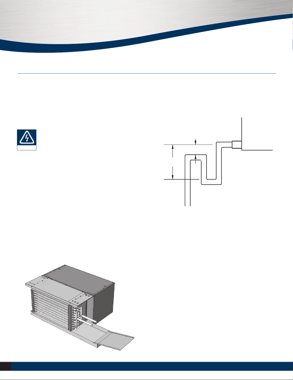
The drain should always be connected and piped to an acceptable disposal
point. For proper moisture carry-off, the drain piping should be sloped
away from the unit at least 1/8” per foot. A drain trap may be required by
local codes and it is strongly recommended for odor containment.
caution
Condensate Trap
“H” MUST BE AT LEAST
1 INCH PLUS CASING
ST
ATIC PRESSURE
H
X
“X” MUST BE
AT
LEAST 1 INCH
7
Installation Manual – THH
Redefine your comfort zone. ™ | www.titus-hvac.com
RETURN AIR LOCATION
This unit is equipped with a field reversible rear or bottom ducted air
return for plenum style units. To change the return air location, remove the
reversible plenum box panel and the filter rack. Rotate both the reversible
panel and filter rack 180 degrees. Replace the reversible panel in the old
filter rack position and fasten using the supplied screws. Fasten the filter
rack to the location where the reversible panel was and replace the filter(s)
as described above.
Section 1 - Receipt & Initial Installation
FAN REMOVAL
This fan assembly is easily removable by unscrewing the (4) E-20 nuts from
the fan deck and sliding the fan assembly off of the weld studs. Disconnect
motor wiring. Reassemble fans and torque nuts to 30 in/lbs.
PLENUM BOX SERVICE PANEL
The service panel on the plenum box is easily removable by removing the
screws located on the sides and bottom of the service panel.
PLENUM BOX REMOVAL
In most cases this unit is fully serviceable without the need for removal of
the plenum box. However should the need arise, the plenum box is easily
removable by removing the screws attaching the plenum box to the sides,
top and rear of the coil casing.
8Installation Manual – THH Redefine your comfort zone. ™ | www.titus-hvac.com
THH HIGH PERFORMANCE HORIZONTAL
FAN COIL UNITS
Section 1 - Receipt & Initial Installation
COIL HANDING
This unit features a field reversible coil assembly should the need arise
upon installation to change the handing of the coil. To change the coil
handing, remove the plenum box (if applicable) from the coil by removing
all screws to the coil casing. Next, remove the fan(s), fan deck, and top
and bottom casings from the coil. Replace the bottom coil casing in the
top coil casing position and the top coil casing in the bottom coil casing
position and reattach the fan deck, fan(s) and plenum box (if applicable) in
the original locations.
The leaving air side of the fin pack will remain the same
after changing the coil handing.
COILS
All fan coils are available in 2 or 4 pipe configurations. Heating and cooling
coils are field reversible for right or left side connections. On units with
water coils, the maximum water pressure applied to the unit should never
exceed 300 PSIG at 200°F. On units with steam heating coils, the maximum
steam pressure applied to the unit should never exceed 15 PSIG. The drain
piping and steam trap should be sized and routed to allow for proper
condensate flow. (Minimum ambient temperature 35°F. Coils may freeze.)
PIPING CONNECTIONS
Toxic residues and loose particles resulting from
manufacturing and field piping techniques such as joint
compounds, soldering flux, and metal shavings may be
present in the unit and the piping system. Special
consideration must be given to system cleanliness when
connecting to solar,domestic or potable water systems.
Submittals and Product Catalogs detailing unit operation, controls, and
connections should be thoroughly reviewed BEFORE beginning the
connection of the various cooling and/or heating mediums to the unit.
All accessory valve packages should be installed as required, and all valves
should be checked for proper operation.
note
caution
If coil and valve package connections are to be made with “sweat”
or solder joint, care should be taken to assure that no components in the
valve package are subjected to a high temperature which may damage
seals or other materials. Many two-position electric control valves,
depending on valve operation, are provided with a manual-opening lever.
This lever should be placed in the “open” position during all soldering or
brazing operations. Valve bodies should be wrapped with a wet rag to help
dissipate heat encountered during brazing. Use a brazing alloy to make
connections such as BCup- 2. Soft solder is not recommended.
If the valve package connection at the coil is made with a union, the coil
side of the union must be prevented from twisting (“backed up”) during
tightening to prevent damage to the coil tubing. Over-tightening must be
avoided to prevent distorting the union seal surface and destroying the
union. In the case of field installed valves and piping, the chilled water
valve cluster (or expansion valve on DX units) should be installed in such
a way that any dripping or sweating is contained in the auxiliary drain pan
or other device. Valves and TXV’s should be secured or supported to avoid
damage to coil headers or distributor tubes.
DUCT WORK CONNECTIONS
All duct work and/or supply and return grilles should be installed in
accordance with the project plans and specifications. If not included on
the unit or furnished from the factory, Johnson Controls supply and return
grilles are available in a variety of types.
All units must be installed in non-combustible areas. Some models are
designed to be connected to duct work with a MINIMUM amount of
external static pressure. Consult the approved submittals and the product
catalog for unit external static pressure limitations.
Units provided with outside air for ventilation should have some form of
low temperature protection to prevent coil freeze-up. Outside air should be
pretreated for best results.
It should be noted that none of these methods would adequately protect
a coil in the event of power failure. The safest method of freeze protection
is to use glycol in the proper percent solution for the coldest expected air
temperature. Consult glycol supplier literature for correct solution ratios.
The manufacturer assumes no responsibility for undesirable system
operation due to improper design, equipment or component selection, and/
or installation of duct work, grilles, and other field supplied components.
9
Installation Manual – THH
Redefine your comfort zone. ™ | www.titus-hvac.com
Section 1 - Receipt & Initial Installation
ELECTRICAL CONNECTIONS
The electrical service to the unit should be compared to the unit nameplate
to verify compatibility. The routing and sizing of all conduit, and the type
and sizing of all wiring and other electrical components such as circuit
breakers, disconnect switches, etc. should be determined by the individual
job requirements and should not be based on the size and/or type of
connection provided on the equipment. All installations should be made in
compliance with all governing codes and ordinances. Compliance with all
codes is the responsibility of the installing contractor. The unit nameplate
lists the unit electrical characteristics such as the required supply voltage,
fan and heater amperage and required circuit ampacities. The unit-wiring
diagram shows all unit and field wiring. Since each project is different
and each unit on a project may be different, the installer must be familiar
with the wiring diagram and nameplate on the unit BEFORE beginning
any wiring. This unit is not acceptable for installation in hazardous/
explosive areas.
CONTROL ENCLOSURE
The optional electrical control enclosure provides access to the electrical
compartment. This compartment houses all electric heat and control
components. Terminal strips are furnished for simple power and control
wiring connections. Multiple knockouts allow wiring entries from either
side of the compartment.
All components furnished for field installation, by either the factory or the
controls contractor should be located and checked for proper function and
compatibility. All internal components should be checked for shipping
damage and all electrical connections should be tightened to minimize
problems during start-up.
Any devices such as fan switches or thermostats that have been furnished
from the factory for field installation must be wired in strict accordance
with the applicable wiring diagrams. Failure to do so could result in
personal injury or damage to components and will void all manufacturers’
warranties.
The fan motor(s) should never be controlled by any wiring or device other
than the factory furnished switch or thermostat/switch combination,
without factory authorization.
All field wiring should be done in accordance with governing codes and
ordinances.Anymodificationoftheunitwiringwithoutfactoryauthorization
willresultinvoidingofallfactorywarrantiesandwillnullifyanyagencylistings.
The manufacturer assumes no responsibility for any damages and/or
injuries resulting from improperly field installed or wired components.
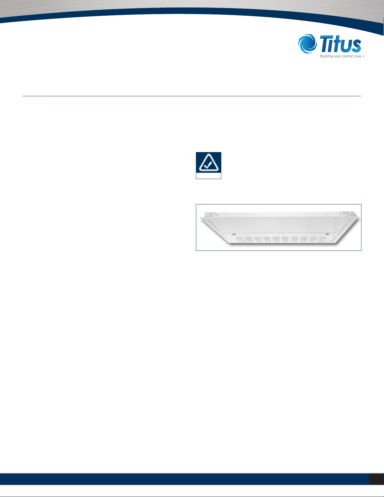
TELESCOPING BOTTOM PANEL
The telescoping bottom panel allows for fully recessing the unit while
permitting service access into the ceiling plenum The architectural ceiling
panel is finished with a durable powder coat paint and comes with
different face options.
Portions of the inlet louver not directly below unit inlet may
require covering in the field on applications where
infiltration of ceiling plenum air into space is undesired.
Telescoping skirt and collar assembly must be field adjusted
to assure a proper fit between filter frame and louvered
inlet panel assembly. Refer to assembly submittal drawings
for specific dimensions.
note

10 Installation Manual – THH Redefine your comfort zone. ™ | www.titus-hvac.com
THH HIGH PERFORMANCE HORIZONTAL
FAN COIL UNITS
Section 2 – Start-Up
START-UP
Before beginning any start-up operation, the startup personnel should
familiarize themselves with the unit, options and accessories, and control
sequence to understand the proper system operation. All personnel should
have a good working knowledge of general start-up procedures and have
the appropriate start-up and balancing guides available for consultation.
The initial step in any startup operation should be a final visual inspection.
All equipment, plenums, duct-work, and piping should be inspected to
verify that all systems are complete and properly installed and mounted,
and that no debris or foreign articles such as paper or drink cans are left
in the units or other areas. Each unit should be checked for loose wires,
free blower wheel operation, and loose or missing access panels or doors.
Except as required during start-up and balancing operations, no fan coil
units should be operated without all the proper duct work attached, supply
and return grilles in place, and all access doors and panels in place and
secure. A clean filter of the proper size and type must also be installed.
Failure to do so could result in damage to the equipment or building and
furnishings, and/or void all manufacturers’ warranties.
COOLING/HEATING SYSTEM
Prior to the water system start-up and balancing, the chilled/hot water
systems should be flushed to clean out dirt and debris, which may have
collected in the piping during construction. During this procedure,all unit
service valves must be in the closed position. This prevents foreign matter
from entering the unit and clogging the valves and metering devices.
Strainers should be installed in the piping mains to prevent this material
from entering the units during normal operation.
During system filling, air venting from the unit is accomplished by the use
of the standard manual or optional automatic, air vent fitting installed
on the coil. In the case of the manual air vent fitting, the screw should
be turned counterclockwise no more than 1-½ turns to operate the air
vent. Automatic air vents may be unscrewed one turn counterclockwise
to speed initial venting but should be screwed in for automatic venting
after start-up operations.
11
Installation Manual – THH
Redefine your comfort zone. ™ | www.titus-hvac.com
The air vent provided on the unit is not intended to replace the main system air vents and may not release air trapped in other parts
of the system. Inspect the entire system for potential air traps and vent those areas as required, independently. In addition, some
systems may require repeated venting over a period of time to properly eliminate air from the system.
note
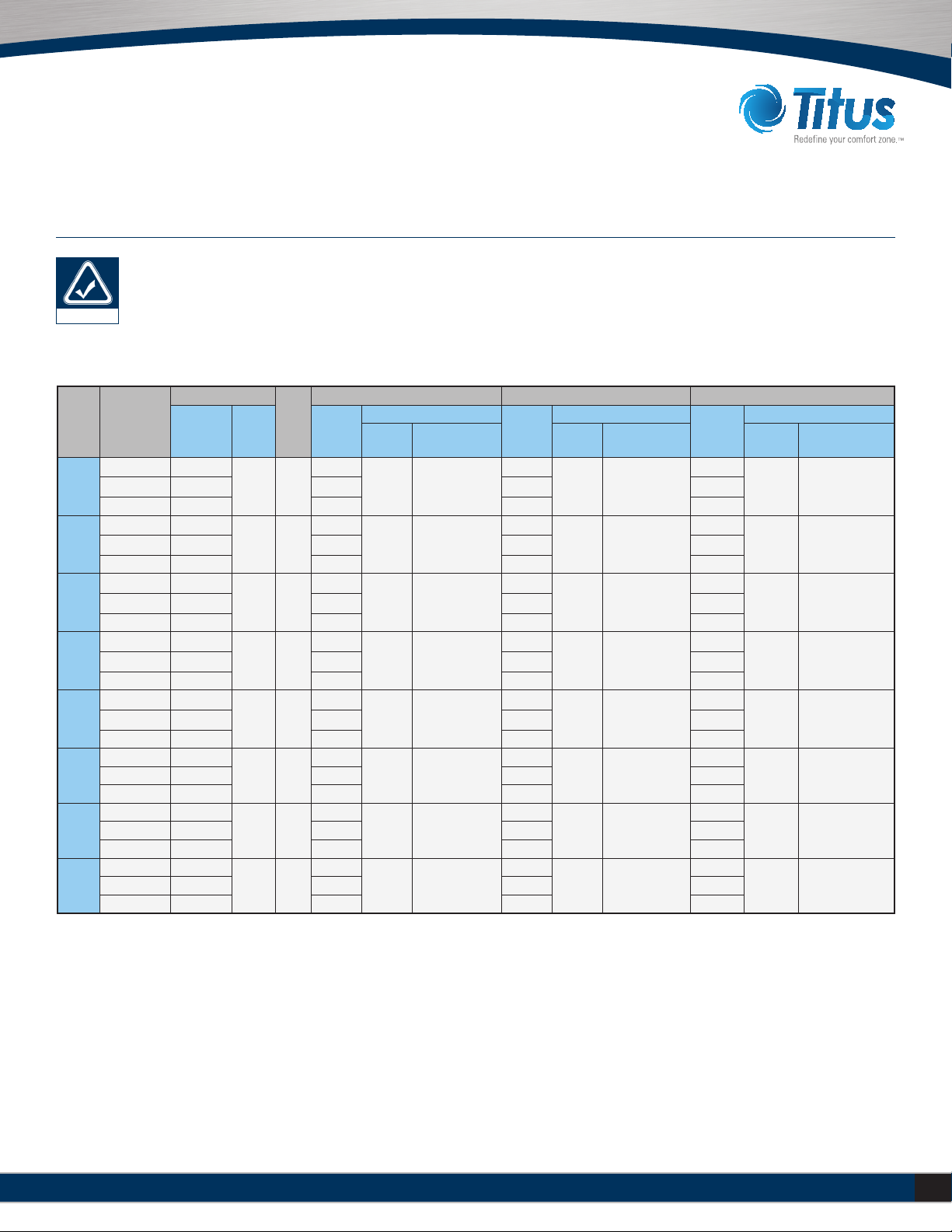
Section 2 – Start-Up
Unit
Size Fan Speed
Motor Fan (Qty)
# of
Fans
Amps 120/1/60 Amps 208-230/1/60 Amps 277/1/60
PSC ECM PSC
ECM
PSC
ECM
PSC
ECM
FLA 3-Phase
Neutral Current FLA 3-Phase
Neutral Current FLA 3-Phase
Neutral Current
06
High (1) 1/6
(1) 1/3 1
2.6
5.0 13.2
1.1
2.8 5.9
0.9
2.6 5.4
Medium (1) 1/8 2.1 0.9 0.8
Low (1) 1/10 1.8 0.6 0.7
08
High (1) 1/4
(1) 1/3 1
3.8
5.0 13.2
1.6
2.8 5.9
1.3
2.6 5.4
Medium (1) 1/6 3.3 1.0 0.8
Low (1) 1/8 2.6 0.8 0.7
10
High (1) 1/4
(1) 1/3 1
4.9
5.0 13.2
2.2
2.8 5.9
1.9
2.6 5.4
Medium (1) 1/5 4.1 1.5 1.2
Low (1) 1/6 3.2 1.1 0.8
12
High (2) 1/6
(2) 1/3 2
5.2
10.0 26.4
2.2
5.6 11.8
1.8
5.2 10.8
Medium (2) 1/8 4.2 1.8 1.6
Low (2) 1/10 3.6 1.2 1.4
14
High (2) 1/4
(2) 1/3 2
7.6
10.0 26.4
3.2
5.6 11.8
2.6
5.2 10.8
Medium (2) 1/6 6.6 2.0 1.6
Low (2) 1/8 5.2 1.6 1.4
16
High (1) 1/4
(2) 1/3 2
9.8
10.0 26.4
4.4
5.6 11.8
3.8
5.2 10.8Medium (1) 1/5 8.2 3.0 2.4
Low (1) 1/6 6.4 2.2 1.6
18
High (1) 1/4
(2) 1/3 2
9.8
10.0 26.4
4.4
5.6 11.8
3.8
5.2 10.8Medium (1) 1/5 8.2 3.0 2.4
Low (1) 1/6 6.4 2.2 1.6
20
High (1) 1/4
(2) 1/3 2
9.8
10.0 26.4
4.4
5.6 11.8
3.8
5.2 10.8Medium (1) 1/5 8.2 3.0 2.4
Low (1) 1/6 6.4 2.2 1.6
MOTOR AND FAN DATA
Notes:
1. Motor electrical data is nameplate data. Actual data will vary with application.
2. 230 volt motor is name plated for 208/230/1/60. Use 230 volt motor data for 208 volt applications
12 Installation Manual – THH Redefine your comfort zone. ™ | www.titus-hvac.com
THH HIGH PERFORMANCE HORIZONTAL
FAN COIL UNITS
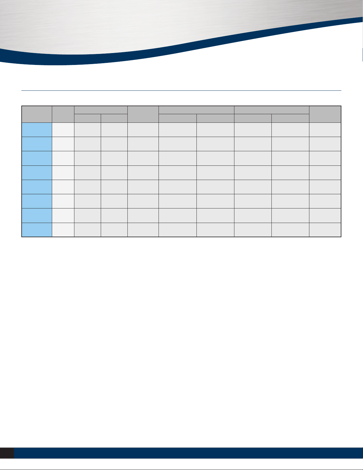
Section 2 – Start-Up
Model/Size AHRI 440
Certified
Coil Airflow CFM
(Dry Flow)
Cooling Capacity Water Power Input
(Watts)
Rows FPI QT (BTUH) QS (BTUH) Flow Rate GPM WPD ft-wg
THHC/THHP
06 * 4 10 700 17800 14000 3.7 1.6 290
THHC/THHP
06 * 4 10 900 23500 18500 4.9 1.9 410
THHC/THHP
10 * 4 10 1100 29400 22900 6.0 2.2 470
THHC/THHP
12 * 4 10 1400 43000 31800 8.7 4.2 560
THHC/THHP
14 4 10 1750 47100 36250 9.6 3.0 715
THHC/THHP
16 4 10 2000 51000 41000 10.5 2.0 830
THHC/THHP
18 4 10 2200 53000 42000 11.0 2.2 850
THHC/THHP
20 4 10 2300 56000 44000 11.4 2.5 870
AHRI STANDARD RATINGS
Notes:
1. Based on 80°F DB and 67°F WB EAT, 45°F EWT, 10°F temperature rise, high speed fan. Motor type is PSC and motor voltage is 115/1/60.
Airflow under dry coil connections. All models tested at 0.05" external static pressure.
2. Airflow rate CFM on sizes 14 through 20 exceed maximum ratings in AHRI 440 and are therefore not certified

13
Installation Manual – THH
Redefine your comfort zone. ™ | www.titus-hvac.com
Section 2 – Start-Up
AIR SYSTEM BALANCING
All duct work must be complete and connected, and all grilles, filters,
access doors and panels must be properly installed to establish actual
system operating conditions BEFORE beginning air balancing operations.
Each individual unit and attached duct work is a unique system with its
own operating characteristics. For this reason, air balancing is normally
done by balance specialists who are familiar with all procedures required
to properly establish air distribution and fan system operating conditions.
These procedures should not be attempted by unqualified personnel.
After the proper system operation is established, the actual unit air
delivery and the actual fan motor amperage draw for each unit should be
recorded in a convenient place for future reference such as the inspection,
installation, & start-up check sheet, a copy of which is provided on the
back of this manual. Contact the Sales Representative or the factory for
additional copies of this sheet.
WATER SYSTEM BALANCING
A complete knowledge of the hydronic system, its components, and
controls is essential to proper water system balancing and this procedure
should not be attempted by unqualified personnel. The system must be
complete and all components must be in operating condition BEFORE
beginning water system balancing operations.
Each hydronic system has different operating characteristics depending
on the devices and controls in the system. The actual balancing technique
may vary from one system to another.
After the proper system operation is established, the appropriate system
operating conditions such as various water temperatures and flow rates
should be recorded in a convenient place for future reference.
Before and during water system balancing, conditions may exist which
can result in noticeable water noise or undesired valve operation due to
incorrect system pressures. After the entire system is balanced, these
conditions will not exist on properly designed systems.
CONTROLS OPERATION
Before proper control operation can be verified all other systems must
be in proper operation. The correct water and air temperatures must
be present for the control function being tested. Some controls and
features are designed to not operate under certain conditions or beyond
designed range.
A wide range of controls and electrical options and accessories may be
used with the equipment covered in this manual. Consult the approved
unit submittals, order acknowledgment, and other manuals for detailed
information regarding each individual unit and its controls. Since controls
and features may vary from one unit to another, care should be taken
to identify the controls to be used on each unit and their proper control
sequence. Information provided by component manufacturers regarding
installation, operation, and maintenance of their individual controls is
available upon request.
PHYSICAL DATA
Each unit on a job will have its own unique operating environment and
conditions that may dictate a maintenance schedule for that unit that is
different from other equipment on the job. A formal schedule of regular
maintenance and an individual unit log should be established and
maintained. This will help to achieve the maximum performance and
service life of each unit on the job.
Information regarding safety precautions contained in the
preface at the beginning of this manual should be followed
during any service and maintenance operations.
For more detailed information concerning service operations, consult your
Sales Representative or the Factory.
MOTOR/BLOWER ASSEMBLY
The type of fan operation is determined by the control components and
their method of wiring, and may vary from unit to unit. Refer to the wiring
diagram for each unit for that unit’s individual operating characteristics.
Motors are permanently lubricated, PSC or ECM type and do not require
field lubrication.
note
14 Installation Manual – THH Redefine your comfort zone. ™ | www.titus-hvac.com
THH HIGH PERFORMANCE HORIZONTAL
FAN COIL UNITS
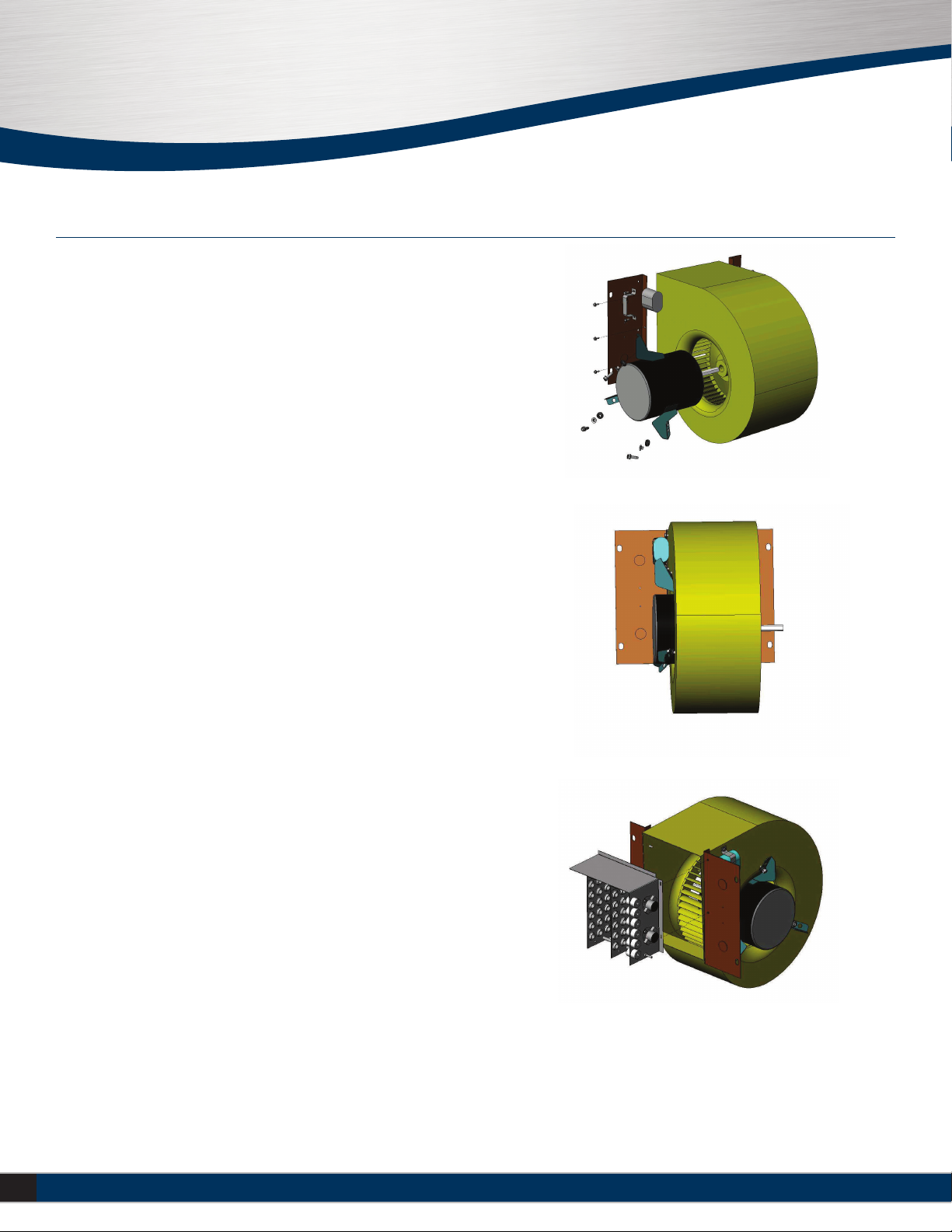
FAN ASSEMBLY
Each fan assembly is easily removed from the unit at four ¼” weld studs
in the fan deck. In most applications the fan assembly can be removed
without disconnecting the duct work for service access to motors and
blowers at, or away from the unit.
Should the assembly require more extensive service,the motor/blower
assembly may be removed from the unit to facilitate such operations as
motor or blower wheel/housing replacement, etc. Dirt and dust should
not be allowed to accumulate on the blower wheel or housing. This can
result in an unbalanced blower wheel condition that can damage a blower
wheel or motor. The wheel and housing may be cleaned periodically using
a vacuum cleaner and a brush taking care not to dislodge the factory
balancing weights on the blower wheel blades.
To remove the motor from the fan, disconnect the motor wire leads, loosen
the set screw on the motor shaft and remove the (3) cap screws that
attached the motor to the blower housing. To reassemble, insert the motor
into the blower wheel, (motor slots to be facing up) center the blower
wheel within the blower housing and tighten the set screw. Reinstall the
(3) cap screws and tighten to 40 in/lbs. Place the entire fan assembly back
up over the weld studs, install the washers and tighten the 1/4-20 nylok
nuts to 65 in/lbs.
COIL
Coils may be cleaned in place by removing the motor/blower assemblies
and brushing the entering air face between fins with a soft brush parallel
to fins.
Do not brush perpendicular to fin orientation as damage may occur.
Brushing should be followed by cleaning with a vacuum cleaner. If a
compressed air source is available, the coil may also be cleaned by blowing
air through the coil fins from the leaving air face. Vacuuming should again
follow this. Units provided with the proper type of air filters, replaced
regularly, may require periodic coil cleaning.
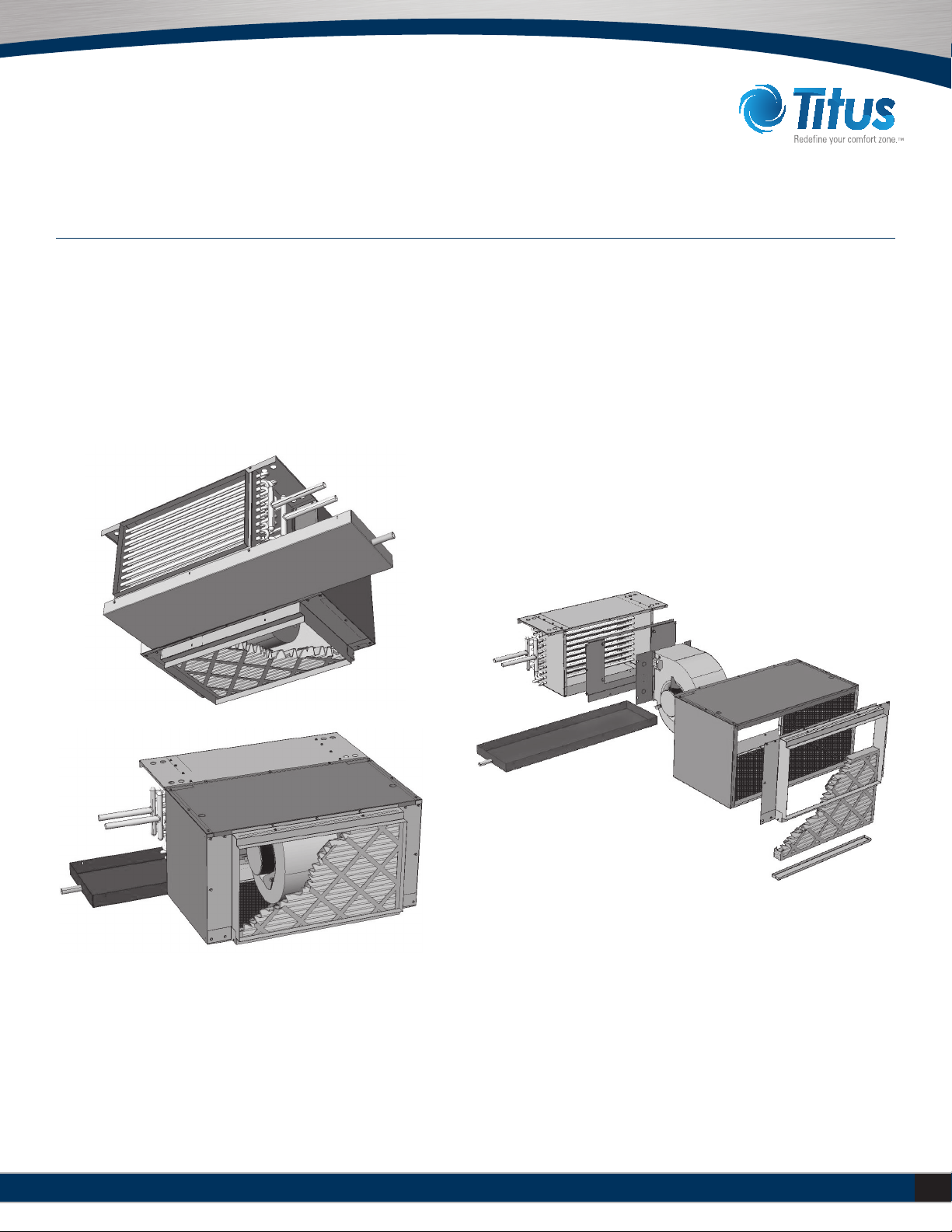
Section 3 – Normal Operation & Periodic Maintenance
Fan Assembly Removal
Electric Heater Removal

15
Installation Manual – THH
Redefine your comfort zone. ™ | www.titus-hvac.com
Section 3 - Normal Operation & Periodic Maintenance
Motor/blower assembly can be removed by pulling two screws from the frame. Fan deck
designed to not exceed 44”.
UNIT WEIGHT DATA
Component Unit Size
08 08 10 12 14 16 18 20
THHC Base Unit 68 [31] 73 [33] 77 [35] 114 [52] 119 [54] 124 [56] 128 [58] 132 [60]
THHP Base Unit 87 [40] 95 [43] 101 [46] 141 [64] 150 [68] 157 [71] 164 [75] 170 [77]
THHP with Mixing Box 119 [54] 132 [60] 144 [65] 189 [86] 204 [93] 217 [99] 229 [104] 246 [112]
THHE Base Unit 137 [62] 146 [66] 158 [72] 202 [92] 219 [99] 228 [103] 240 [109] 250 [113]
Total
Coil
Rows
1 Row - Dry 5 [2] 6 [3] 7 [3] 8 [4] 10 [5] 10 [5] 11 [5] 12 [5]
1 Row - Wet 7 [3] 9 [4] 10 [5] 11 [5] 14 [6] 14 [6] 16 [7] 17 [8]
2 Row - Dry 11 [5] 13 [6] 14 [6] 16 [7] 20 [9] 20 [9] 22[10] 24 [11]
2 Row - Wet 14 [6] 18 [8] 20 [9] 23 [10] 27 [12] 28 [13] 32 [15] 35 [16]
3 Row - Dry 16 [7] 19 [9] 21 [10] 24 [11] 30 [13] 30 [14] 33 [15] 36 [16]
3 Row - Wet 21 [10] 27 [12] 30 [14] 34 [15] 41 [19] 42 [19] 48 [22] 52 [24]
4 Row - Dry 21 [10] 25 [12] 29 [13] 33 [15] 40 [18] 40 [18] 44 [20] 48 [22]
4 Row - Wet 27 [12] 35 [16] 41 [19] 46 [21] 54 [25] 56 [25] 64 [29] 69 [31]
5 Row - Dry 26 [12] 30 [14] 34 [16] 38 [17] 42 [19] 46 [21] 50 [23] 54 [25]
5 Row - Wet 33 [15] 39 [18] 45 [21] 51 [23] 57 [26] 63 [29] 70 [32] 77 [35]
6 Row - Dry 32 [15] 38 [17] 43 [19] 49 [22] 59 [27] 61 [28] 67 [30] 71 [32]
6 Row - Wet 42 [19] 53 [24] 61 [28] 69 [31] 80 [36] 85 [39] 97 [44] 103 [47]
7 Row - Dry 38 [17] 42 [19] 48 [22] 54 [25] 60 [28] 66 [30] 72 [33] 78 [35]
7 Row - Wet 49 [23] 56 [26] 63 [29] 70 [32] 77 [35] 84 [38] 91 [42] 98 [45]
8 Row - Dry 43 [20] 49 [22] 55 [25] 61 [28] 67 [30] 73 [33] 79 [36] 85 [39]
8 Row - Wet 55 [26] 63 [29] 71 [32] 79 [36] 87 [40] 95 [43] 103 [47] 111 [50]
Notes: Unit weight data is in pounds [kilograms]

16 Installation Manual – THH Redefine your comfort zone. ™ | www.titus-hvac.com
THH HIGH PERFORMANCE HORIZONTAL
FAN COIL UNITS
Section 3 - Normal Operation & Periodic Maintenance
ELECTRIC RESISTANCE HEATER ASSEMBLY
Electric resistance heaters typically require no normal periodic maintenance
when unit air filters are changed properly. Other conditions and equipment
may affect the operation and service life in the system. The two most
important operating conditions for an electric heater are proper airflow
and proper supply voltage. High supply voltage and/or poorly distributed
or insufficient airflow over the element will result in element overheating.
This condition may result in the heater cycling on the high limit thermal
cutout. The open wire type heaters provided have an automatic reset
switch with a back-up high limit thermal switch. Automatic reset switches
are as the name implies; they reset automatically after the heater has
cooled down. High limit thermal switches must be replaced once the
circuit has been broken. The high limit thermal cutout device is a safety
device only and is not intended for continuous operation. With proper unit
application and during normal operation, the high limit thermal cutout will
not operate. This device only operates when some problem exists and ANY
condition that causes high limit cutout MUST be corrected immediately.
High supply voltage also causes excessive amperage draw and may result
in tripping of the circuit breaker or blowing of the fuses on the incoming
power supply.
ELECTRICAL WIRING & CONTROLS
The electrical operation of each unit is determined by the components
and wiring of the unit and may vary from unit to unit. Consult the
wiring diagram for the actual type and number of controls provided on
each unit. The integrity of all electrical connections should be verified
at least twice during the first year of operation. Afterwards, all controls
should be inspected regularly for proper operation. Some components
may experience erratic operation or failure due to age. Wall thermostats
may also become clogged with dust and lint and should be periodically
inspected and cleaned to provide reliable operation.
When replacing any components such as fuses, contactors, or relays,
use only the exact type, size, and voltage component as furnished from
the factory. Any deviation without factory authorization could result in
personnel injury or damage to the unit and will void all factory warranties.
All repair work should be done in such a manner as to maintain the
equipment in compliance with governing codes and ordinances or testing
agency listings.
ELECTRICAL CALCULATIONS INFORMATION
1. Calculate FLA = [(Motor Amps)*(Motor Qty) + (Heater Amps)]
2. Calculate MCA = [(1.25)*(FLA)]3. Calculate MOP =
[(2.25)*(1st Motor Amps) + (2nd Motor Amps) + (Heater Amps)]
a) If the calculated MOP is within 10% of the next smaller available
fuse size, that fuse size shall be used. If the calculated MOP
is not within 10% of the next smaller available fuse size, the next
larger fuse size above the calculated MOP must be used.
b) If the selected MOP is smaller than the MCA, the selected
MOP must be increased to the next larger available fuse size
above the MCA.4. Non-Fused Door Interlock Disconnect Switch
shall be sized according to MCA.
3. Fused Door Interlock Disconnect Switch and Main Fusing shall be
sized according to MOP. Available fuse sizes: 15, 20, 25, 30, 35, 40,
45, 50, 60, 70, 80 and 90. MCA and MOP calculations are based
on requirements from ANSI UL 1995 2nd Edition – CAN/CSA C22.2
No. 236-M90 Standard for Safety; Heating and Cooling Equipment,
which incorporates rules from NFPA 70 National Electric Code
2002 edition.

17
Installation Manual – THH
Redefine your comfort zone. ™ | www.titus-hvac.com
Section 3 - Normal Operation & Periodic Maintenance
Unit
Size
MBH 6.8 8.5 10.2 11.9 13.7 17.1 20.5 23.9 27.3 30.7 34.1 41.0 47.8
KW 2.0 2.5 3.0 3.5 4.0 5.0 6.0 7.0 8.0 9.0 10.0 12.0 14.0
Volts AMPs
06
115 17.4 21.8 26.1 30.5 34.8
208 9.6 12.0 14.4 16.8 19.2
230 8.7 10.9 13.1 15.2 17.4
277 7.2 9.0 10.8 12.6 14.4
08
115 17.4 21.8 26.1 30.5 34.8 43.5
208 9.6 12.0 14.4 16.8 19.2 24.1 28.9
230 8.7 10.9 13.1 15.2 17.4 21.8 26.1
277 7.2 9.0 10.8 12.6 14.4 18.1 21.7
10
115 17.4 21.8 26.1 30.5 34.8 43.5
208 9.6 12.0 14.4 16.8 19.2 24.1 28.9 33.7
230 8.7 10.9 13.1 15.2 17.4 21.8 26.1 30.5
277 7.2 9.0 10.8 12.6 14.4 18.1 21.7 25.3
12
115 34.8 43.5
208 19.2 24.1 28.9 33.7 38.5 43.3
230 17.4 21.8 26.1 30.5 34.8 39.2
277 14.4 18.1 21.7 25.3 28.9 32.5
14
115 34.8 43.5
208 19.2 24.1 28.9 33.7 38.5 43.3 48.1
230 17.4 21.8 26.1 30.5 34.8 39.2 43.5
277 14.4 18.1 21.7 25.3 28.9 32.5 36.1
16
115 34.8 43.5
208 19.2 24.1 28.9 33.7 38.5 43.3 48.1 57.7
230 17.4 21.8 26.1 30.5 34.8 39.2 43.5 52.2
277 14.4 18.1 21.7 25.3 28.9 32.5 36.1 43.3
18
115 34.8 43.5
208 19.2 24.1 28.9 33.7 38.5 43.3 48.1 57.7
230 17.4 21.8 26.1 30.5 34.8 39.2 43.5 52.2
277 14.4 18.1 21.7 25.3 28.9 32.5 36.1 43.3
20
115 34.8 43.5
208 19.2 24.1 28.9 33.7 38.5 43.3 48.1 57.7 67.3
230 17.4 21.8 26.1 30.5 34.8 39.2 43.5 52.2 60.9
277 14.4 18.1 21.7 25.3 28.9 32.5 36.1 43.3 50.5
ELECTRIC HEAT SELECTION CHART (AMPS)
Notes:
1. Shaded areas indicate kW and voltage options not avialable
2. Available voltages are single phase, 60 hertz.
3. Heaters over 48 AMPs are subdivided and fused per NEC
18 Installation Manual – THH Redefine your comfort zone. ™ | www.titus-hvac.com
THH HIGH PERFORMANCE HORIZONTAL
FAN COIL UNITS
furnished from or recommended by the factory. Optional 1” and 2” pleated
filters are available and can be used in this unit. Contact the local Sales
Representative for the correct filter upgrade specification and availability.
Consult the factory for applications using filter types other than the factory
standard or optional product.
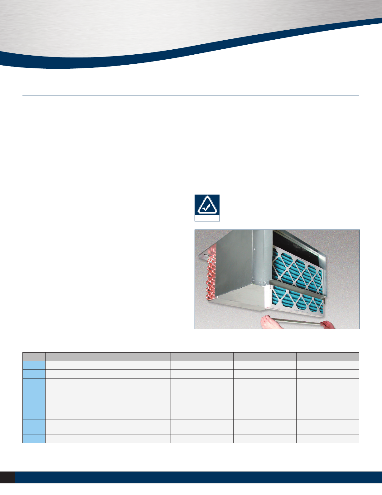
FILTER REPLACEMENT
To replace the filter(s), unscrew the thumb screws located at the bottom of
the filter bracket a few turns until the filter tray freely slides out. Slide out
the used filter(s) and replace with the new one(s). Reattach the filter tray
to the filter bracket with the supplied thumb screws.
Section 3 - Normal Operation & Periodic Maintenance
VALVES & PIPING
No formal maintenance is required on the valve package components most
commonly used with fan coil units other than a visual inspection for possible
leaks in the course of other normal periodic maintenance. In the event that
a valve should need replacement, the same precautions taken during the
initial installation to protect the valve package from excessive heat should
also be used during replacement. In some cases, the valve actuator may
fail and usually can be replaced without removing valve body from piping.
DRAIN
The drain should be checked before initial start-up and at the beginning of
each cooling season to assure that the lines are clear. If it is clogged, steps
should be taken to clear the debris so that condensate will flow easily.
Periodic checks of the drain should be made during the cooling season
to maintain a free flowing condensate. Should the growth of algae and/
or bacteria be a concern, consult an air conditioning and refrigeration
supply organization familiar with local conditions for chemicals available
to control these agents.
FILTERS
This unit is equipped with a standard 1” throwaway filter most commonly
used on fan coil units should be replaced on a regular basis. The time
interval between each replacement should be established based on regular
inspection of the filter and should be recorded in the log for each unit.
At a minimum, filters should be inspected monthly and replaced if needed.
Refer to the Filters chart for recommended filter size for each product type
and size. If the replacement filters are not purchased from the factory,
the filters used should be the same type, size and MERV rating as that
Unit Size Coil Face Area Nominal filter sizes 1 “ Throwaway Face Area 1” Pleated Gross Media Area 2” Pleated Gross Media Area
06 1.56 [0.15] (1) 16 x16 [406 x 406] 1.62 [0.15] 4.0 [0.37] 5.4 [.050]
08 2.08 [0.19] (1) 16 x 20 [406 x 508] 2.04 [0.19] 4.8 [0.45] 6.8 [0.63]
10 2.50 [0.23] (1) 16 x 25 [406 x3 81] 2.57 [0.24] 6.0 [0.56] 8.5 [0.79]
12 3.02 [0.28] (2) 16 x16 [406 x 406] 3.23 [0.30] 8.0 [0.74] 10.4 [0.97]
14 3.54 [0.33] (1) 16 x16 & (1) 16 x 20
(1) 406 x 406 (1) 406 x 508 3.65 [0.34] 8.8 [0.82] 12.2 [1.13]
16 4.06 [0.38] (2) 16 x20 {406 x508] 4.08 [0.38] 9.6 [0.89] 13.4 [1.24]
18 4.58 [0.43] (1) 16 x 20 & (1) 16 x 25
(1) [406 x 508] & (1) [406 x 635] 4.61 [0.43] 10.8 [1.00] 14.3 [1.33]
20 5.00 [0.46] (2) 16 x25 [406 x635] 5.14 [0.48] 12.0 [1.11] 17.0 [1.58]
FACE AREA, FREE AREA AND FILTER SIZES
The filter tray is fully adjustable and can be rotated 180
degrees if necessary to ensure a snug fit between the filter
and the filter bracket.
note
Notes:
1. Face and free areas are in square feet [square meters]
2. Filter sizes are in inches [millimeters]

19
Installation Manual – THH
Redefine your comfort zone. ™ | www.titus-hvac.com
Section 3 - Normal Operation & Periodic Maintenance
REPLACEMENT PARTS
Factory replacement parts should be used wherever possible to maintain
the unit performance and operating characteristics and the testing
agency listings. Replacement parts may be purchased through the local
Sales Representative.
Contact the local Sales Representative before attempting any unit
modifications. Any modifications not authorized by the factory could
result in personal injury and damage to the unit and could void all
factory warranties.
When ordering parts, the following information must be supplied to
ensure proper part identification:
1. Complete unit model number
2. Unit hand connection (right or left hand) while facing the direction
of airflow at the inlet
3. Complete part description including any numbers
On warranty replacements, in addition to the information previously
listed, the project CO # that appears on the unit nameplate, is required.
Contact the factory for authorization to return any parts such as defective
parts replaced in warranty. All shipments returned to the factory
MUST be marked with a Return Authorization Number, which is provided
by the factory.
All equipment and components sold through Johnson Controls are
warranted under the same conditions as the standard manufacturer’s
warranty with the exception that the warranty period is 12 months unless
the component is furnished as warranty replacement. Parts furnished
as warranty replacements are warranted for the remaining term of the
original unit warranties.
20 Installation Manual – THH Redefine your comfort zone. ™ | www.titus-hvac.com
THH HIGH PERFORMANCE HORIZONTAL
FAN COIL UNITS
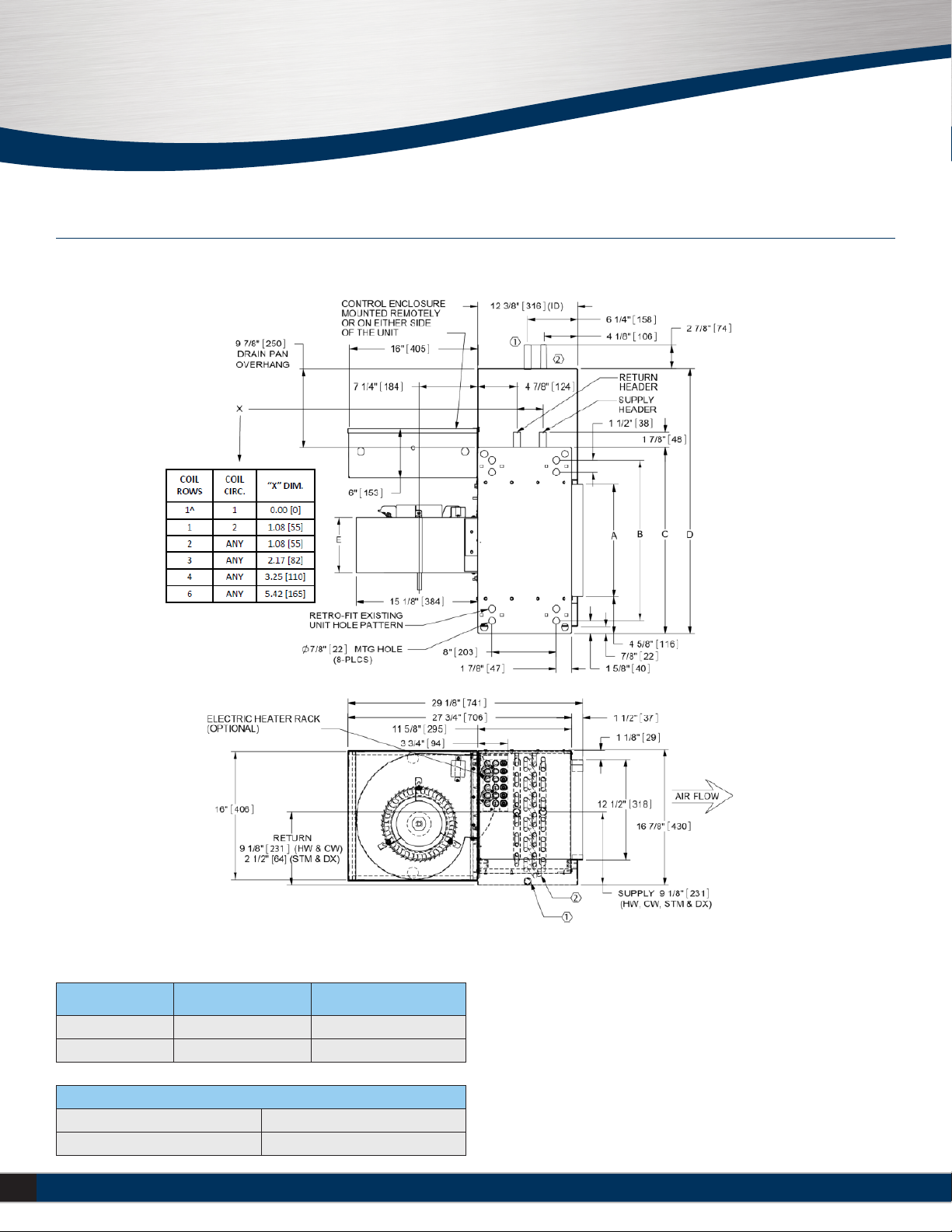
Notes:
1. Standard control enclosure is mounted on unit side opposite
cooling coil connections. Unit casing includes (2) knock outs
on each side. Provide sufficient clearance to access electrical controls
and comply with applicable codes and ordinances.
2. Optional bottom control enclosure with hinged cover replaces
standard side mounted enclosure and includes (2) additional knockouts
on bottom of unit on left side
3. Standard externally foam coated galvanized steel drain pan has
7/8” ODM copper outlet. Stainless steel drain pan has 3/4” MPT
galvanized steel outlet.
4. Auxiliary drain outlet is 5/8” ODM copper or 3/8” MPT galvanized
steel respectively
Section 3 - Normal Operation & Periodic Maintenance
Model THHC - Free Return Dimensions
Drain Pan Material Single Connection (STD) Secondary Connection (OPT)
Galvanized (STD) 7/8’ od copper 5/8” od copper
Stainless (opt) 3/4” mpt galv. 1/2” mpt galv.
Control Enclosure Sizes
10 x 16 x 6 250 x406 x 152
16 x 16 x 6 406 x 406 x 152
This manual suits for next models
14
Other Titus Fan manuals


