manuals.online logo
Brands
  1. Home
  2. •
  3. Brands
  4. •
  5. TJERNLUND
  6. •
  7. Switch
  8. •
  9. TJERNLUND PS1503 DUCT AIRSTAT FAN PROVING SWITCH REV A... User manual

TJERNLUND PS1503 DUCT AIRSTAT FAN PROVING SWITCH REV A... User manual

MODEL PS1503
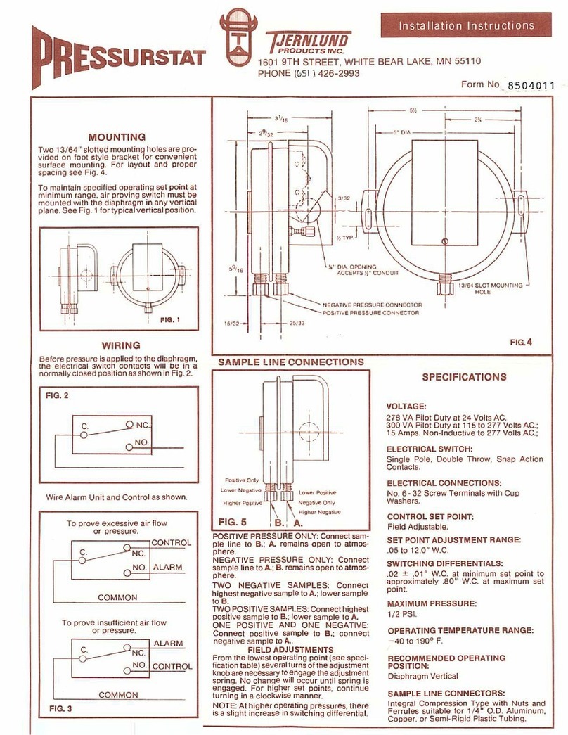
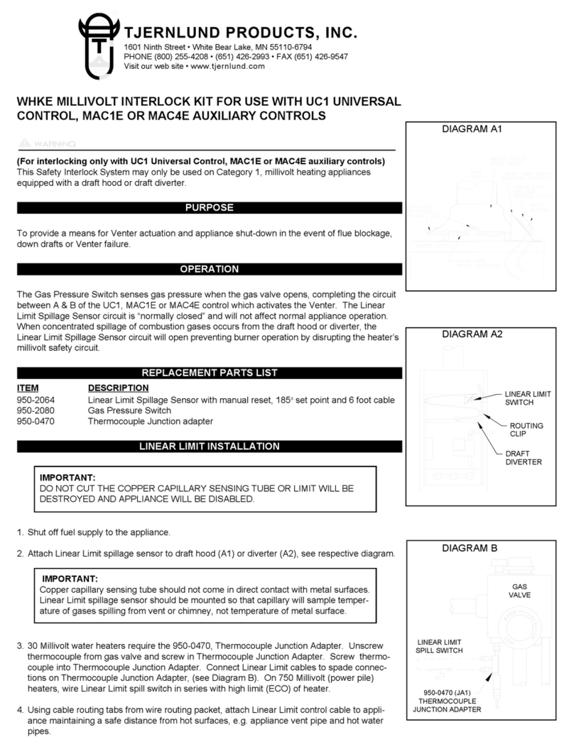
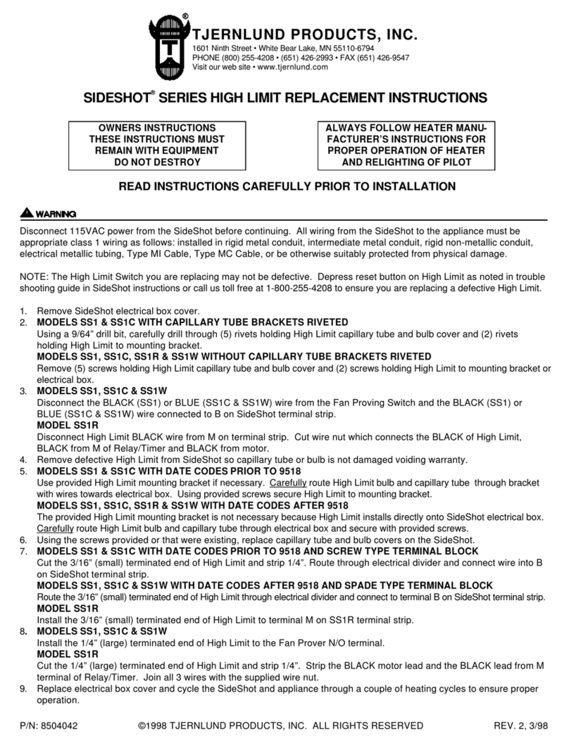
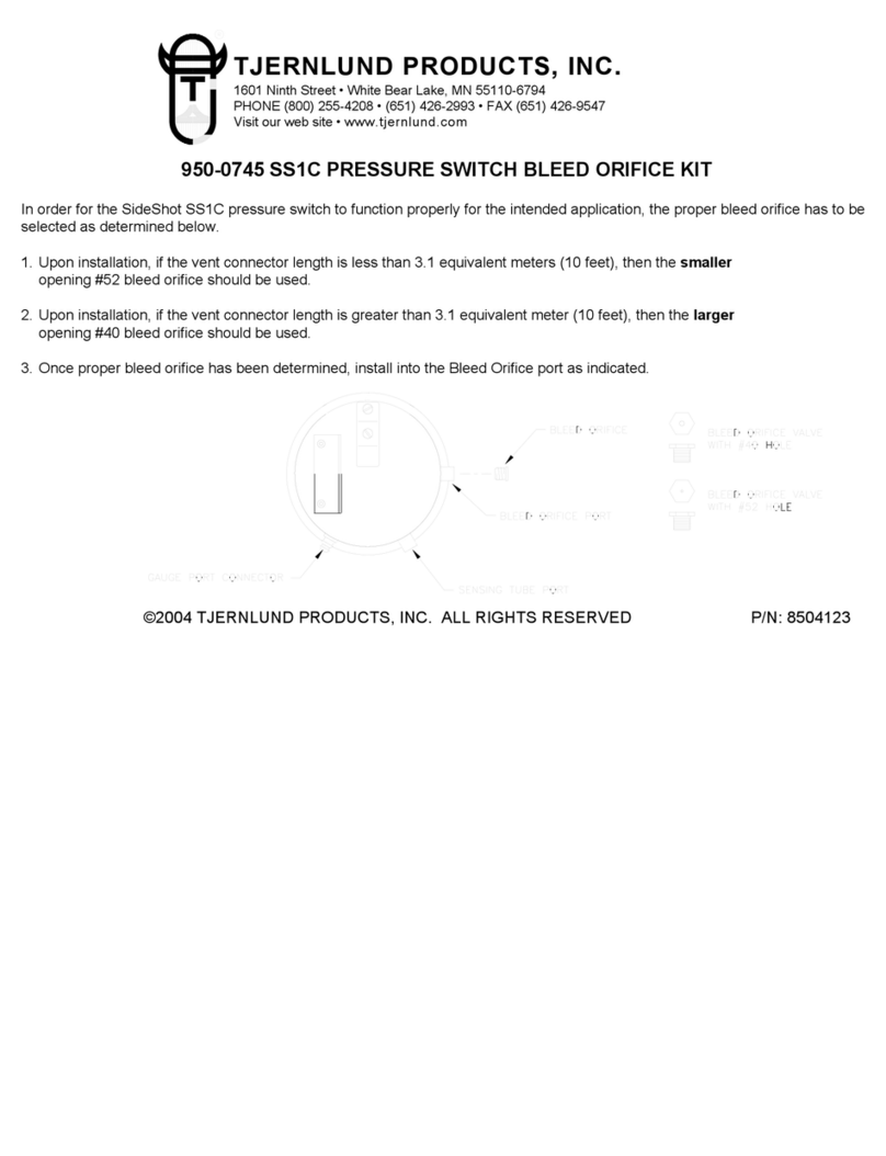
The Tjernlund Duct Airstat senses positive pressure in a forced
air heating and/or cooling system. The single pole, single throw,
snap-acting switch is activated by a diaphragm with integral
pressure probe inserted directly into the duct or plenum.
The Duct Airstat can be used to initiate such auxiliary devices
as: Duct Boosters, Electronic Air Cleaners, Electrical Duct
Heaters, and Humidifiers. The electrical contacts of the switch
are closed upon sensing positive air pressure generated by the
blower.
Switch actuates air
cleaner by sensing
positive plenum pressure.
Switch activates humidifier
by sensing positive plenum
pressure.
Switch proves operation
of blower by sampling
positive pressure.
ELECTRONIC AIR CLEANERS HUMIDIFIERS FAN OPERATION
Switch activates Duct Booster by sensing positive pressure on either plenum, trunk, or branch lines as shown in Figures A and B above.
TYPICAL MOUNTING LOCATIONS & APPLICATIONS
AB
Trunk Line
Plenum
115-120V
Duct
Airstat
Duct
Booster
Electronic
Air Cleaner
Electronic
Duct Heater Humidifier
Duct Booster
Branch
Run
WIRING:
All wiring must agree with applicable electrical codes
and ordinances. Typical diagrams are shown below.
SWITCH MUST BE
MOUNTED WITH
DIAPHRAGM IN
VERTICAL POSITION
TJERNLUND PRODUCTS, INC.
1601 Ninth Street • White Bear Lake, MN 55110-6794
PHONE (651) 426-2993 • FAX (651) 426-9547
Visit our web site • www.tjernlund.com
SIDE VIEW TOP VIEW
LOCATION AND MOUNTING:
1. The duct Airstat must be mounted in a vertical position.
2. Drill a 11/32” hole in the duct or plenum to permit the inser-
tion the pressure probe. If furnace has central air-condi-
tioning, care must be taken so as not to drill into the cooling
coil when mounting the Duct Airstat on the furnace plenum.
3. Insert the pressure probe into the drilled hole, position the
Duct Airstat and mark the mounting holes. If necessary,
bend the mounting feet with pliers to match the contour of
the duct or plenum.
4. Remove control and drill or punch two 1/8” holes for
mounting screws.
5. Using the two sheet metal screws furnished, fasten the Duct
Airstat to the duct or plenum. Sealing gasket must be
mounted on pressure probe to ensure minimal air leakage.
OWNERS
INSTRUCTIONS
DO NOT DESTROY
DUCT AIRSTAT INCLUDES:
1. A fixed “fan-on” setpoint
(+ .05 + .02” W.C.)
2. Integral pressure probe
3. Sealing gasket
4. Mounting hardware
INSTALLATION:
CAUTION
1. Disconnect power supply before making wiring
connections to prevent electrical shock and
equipment damage.
2. All wiring must comply with applicable codes and
ordinances.
3. Always conduct a thorough checkout when installa-
tion is complete.
SEALING
GASKET
PRESSURE
PROBE
GENERAL SPECIFICATIONS:
ELECTRICAL RATING:
278 VA Pilot Duty at 24 Volts AC
300 VA Pilot Duty at 115 to 277 Volts AC
15 AMPS Non-Inductive to 277 Volts AC
ELECTRICAL SWITCH:
SPST, N/O, Snap Action Contacts, Non Adjustable
OPERATING PRESSURE / POSITION:
On pressure rise at +.05 + .02” W.C. (Diaphragm Vertical)
MAXIMUM PRESSURE:
1/2 PSI
OPERATING TEMPERATURE RANGE:
-40 to 1900F.
OPERATING POSITION:
Diaphragm must be vertical
PRESSURE PROBE:
Self-sealing, integral pressure probe
DIMENSIONS:
5” Diam., 5 1/2” Across Bracket, 3” High
To connect to screw-in terminals, use the following
procedures:
1. Remove electrical box cover.
2. No. 14, 16 or 18 solid or No. 14 or 16 stranded wire
may be connected to these terminals. Do not connect
aluminum wire to the screw-in terminals on this device.
3. Strip insulation from wires approximately 1/2”.
4. Bend each bare lead around its respective terminal in
a clockwise direction and tighten terminal screw.
5. Replace the electrical box cover when connections
are complete.
© 1999 Tjernlund Products, Inc. P/N 8504014 Rev. A 10/99
TJERNLUND LIMITED ONE YEAR WARRANTY
Tjernlund Products, Inc. warrants to the original purchaser of this product that the product will be free from defects due to faulty material or workmanship
for a period of (1) year from the date of original purchase or delivery to the original purchaser, whichever is earlier. Remedies under this warranty are
limited to repairing or replacing, at our option, any product which shall, within the above stated warranty period, be returned to Tjernlund Products, Inc. at
the address listed below, postage prepaid. THERE ARE NO WARRANTIES WHICH EXTEND BEYOND THE DESCRIPTION ON THE FACE HEREOF,
AND TJERNLUND PRODUCTS, INC. EXPRESSLY DISCLAIMS LIABILITY FOR INCIDENTAL OR CONSEQUENTIAL DAMAGES ARISING FROM THE
USE OF THIS PRODUCT. THIS WARRANTY IS IN LIEU OF ALL OTHER EXPRESS WARRANTIES AND NO AGENT IS AUTHORIZED TO ASSUME
FOR US ANY LIABILITY ADDITIONAL TO THOSE SET FORTH IN THIS LIMITED WARRANTY. IMPLIED WARRANTIES ARE LIMITED TO THE STAT-
ED DURATION OF THIS LIMITED WARRANTY. Some states do not allow limitation on how long an implied warranty lasts, so that limitation may not
apply to you. In addition, some states do not allow the exclusion or limitation of incidental or consequential damages, so that above limitation or exclu-
sion may not apply to you. This warranty gives you specific legal rights and you may also have other rights which may vary from State to State. Send
all inquiries regarding warranty work to Tjernlund Products, Inc. 1601 9th Street, White Bear Lake, MN 55110-6794. Phone (651) 426-2993 •
Fax (651) 426-9547.
TROUBLE-SHOOTING:
Installations in larger ducts or “dead spots” in duct work may not create enough positive pressure “impact” to activate the Duct
Airstat. Try locating pressure probe at several points. Contact Tjernlund Products customer service @ 1-800-255-4208 or email
us at [email protected] for further assistance.
OTHER TJERNLUND PRODUCTS
HIGH PRESSURE DUCT FANS DUCT BOOSTER®DUCT & EXHAUST FANS
CONNECTING TO SCREW-IN
TERMINALS:

Other TJERNLUND Switch manuals

TJERNLUND SIDESHOT SS1C INCREASED CAPACITY OIL VENT SYSTEM... User manual

TJERNLUND

TJERNLUND SIDESHOT SS1C INCREASED CAPACITY OIL VENT SYSTEM... User manual

TJERNLUND PS1503 DUCT BOOSTER FAN SWITCH 8500130 REV A... User guide

TJERNLUND

TJERNLUND PS1503 DUCT BOOSTER FAN SWITCH 8500130 REV A... User guide

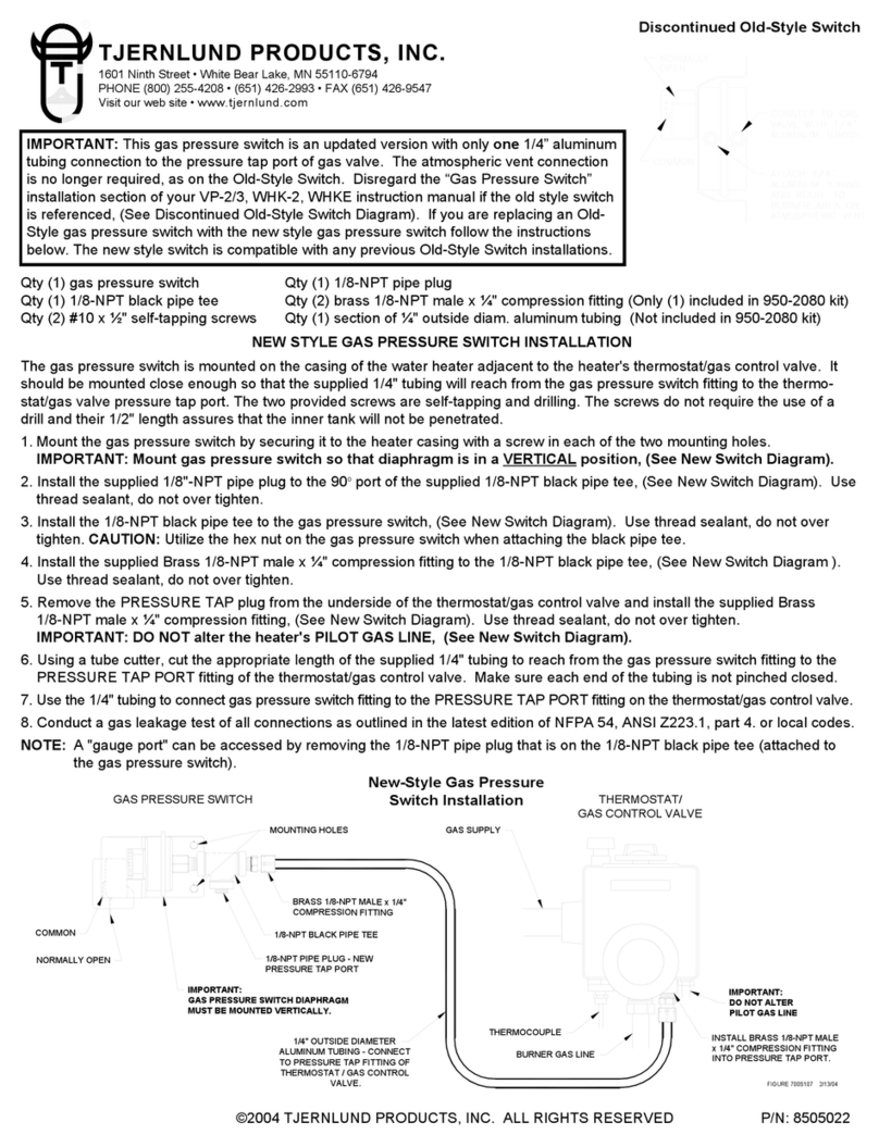
TJERNLUND 950-2080 NEW STYLE GAS PRESSURE SWITCH User manual

TJERNLUND

TJERNLUND 950-2080 NEW STYLE GAS PRESSURE SWITCH User manual

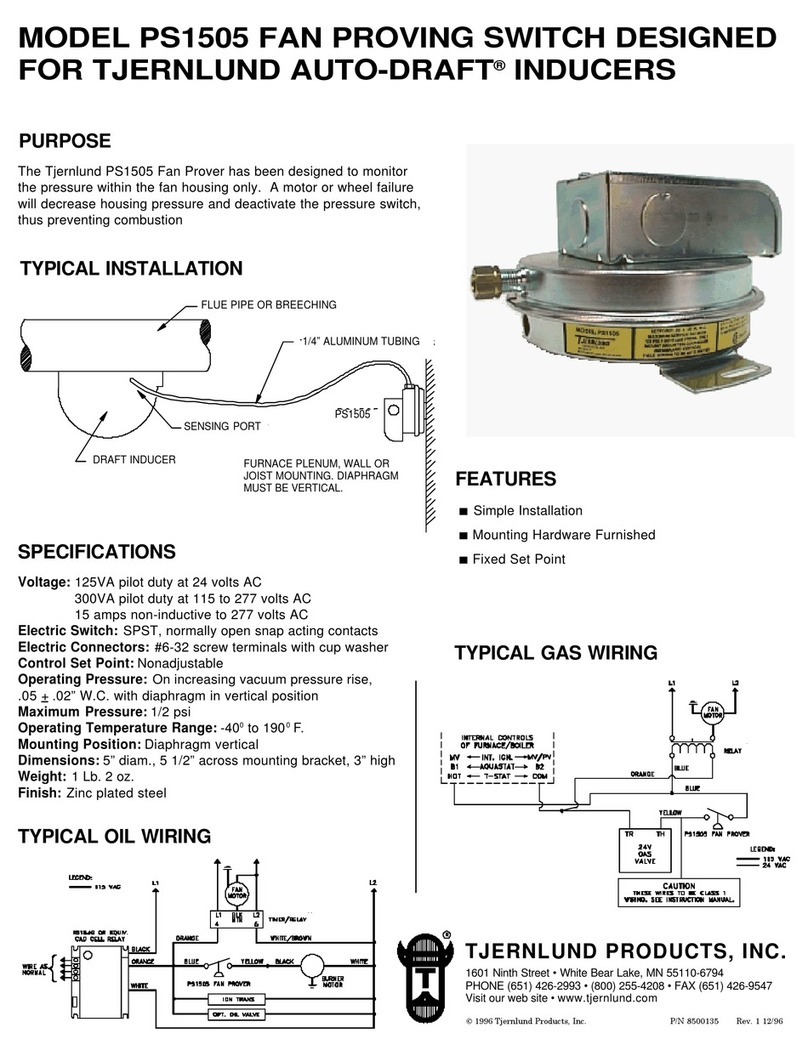
TJERNLUND PS1505 IN-LINE DRAFT INDUCER FAN PROVING SWITCH 8500135 REV 1... User manual

TJERNLUND

TJERNLUND PS1505 IN-LINE DRAFT INDUCER FAN PROVING SWITCH 8500135 REV 1... User manual

TJERNLUND PS2501 FAN PROVING SWITCH User manual
TJERNLUND

TJERNLUND PS2501 FAN PROVING SWITCH User manual

TJERNLUND SideShot SS1 Guide

TJERNLUND

TJERNLUND SideShot SS1 Guide

TJERNLUND SIDESHOT SS2 User manual

TJERNLUND

TJERNLUND SIDESHOT SS2 User manual

TJERNLUND WHKE MILLIVOLT INTERLOCK KIT (COMPATIBLE WITH UC1 CONTROL) 8504108 REV... User manual

TJERNLUND

TJERNLUND WHKE MILLIVOLT INTERLOCK KIT (COMPATIBLE WITH UC1 CONTROL) 8504108 REV... User manual

TJERNLUND PS1505 FAN PROVER 8504008 REV 1 0197 User manual
TJERNLUND

TJERNLUND PS1505 FAN PROVER 8504008 REV 1 0197 User manual

TJERNLUND 950-0452 PAI-1,2 PROVER KIT 8504044 REV. 1... User manual

TJERNLUND

TJERNLUND 950-0452 PAI-1,2 PROVER KIT 8504044 REV. 1... User manual

TJERNLUND SIDESHOT SS2 User manual

TJERNLUND

TJERNLUND SIDESHOT SS2 User manual

TJERNLUND SIDESHOT SS1C INCREASED CAPACITY OIL VENT SYSTEM... User manual
TJERNLUND

TJERNLUND SIDESHOT SS1C INCREASED CAPACITY OIL VENT SYSTEM... User manual
Popular Switch manuals by other brands

Dell S6000-ON installation guide

Dell

Dell S6000-ON installation guide

PESA Cougar Series Open Me First

PESA

PESA Cougar Series Open Me First

Virtualfly SOLO GA1 user manual

Virtualfly

Virtualfly SOLO GA1 user manual

UTEPO UTP3306TS-PSB user manual

UTEPO

UTEPO UTP3306TS-PSB user manual

Cisco Catalyst 6800 Series Quick start configuration guide

Cisco

Cisco Catalyst 6800 Series Quick start configuration guide

HK Instruments PS Series installation instructions

HK Instruments

HK Instruments PS Series installation instructions

TRENDnet TEG-S18TX Specifications

TRENDnet

TRENDnet TEG-S18TX Specifications

SWiiD SwiidInter Installation and user guide

SWiiD

SWiiD SwiidInter Installation and user guide

D-Link DES-1218 user guide

D-Link

D-Link DES-1218 user guide

Pittway System Sensor EPS10EXP Installation and maintenance instructions

Pittway

Pittway System Sensor EPS10EXP Installation and maintenance instructions

Enterasys SecureStack B3 Configuration guide

Enterasys

Enterasys SecureStack B3 Configuration guide

PKP FOS01 instruction manual

PKP

PKP FOS01 instruction manual

StarTech.com SV841DUSBI manual

StarTech.com

StarTech.com SV841DUSBI manual

Compaq Storageworks SAN Switch 8 Installation and hardware guide

Compaq Storageworks

Compaq Storageworks SAN Switch 8 Installation and hardware guide

Linksys SRW2024 Product data

Linksys

Linksys SRW2024 Product data

Comtrol ROCKET LINX MP1204-XT Quick installation guide

Comtrol

Comtrol ROCKET LINX MP1204-XT Quick installation guide

Sunbather Wireless SunSwitch operating instructions

Sunbather

Sunbather Wireless SunSwitch operating instructions

Philio PSR07 manual

Philio

Philio PSR07 manual

manuals.online logo
manuals.online logoBrands
  • About & Mission
  • Contact us
  • Privacy Policy
  • Terms and Conditions

Copyright 2025 Manuals.Online. All Rights Reserved.