TK TFP-9 User manual

1
Operator’s Safety and Service Manual
Scarifier
TFP-9
It is the OWNER´S RESPONSABILITY to communicate information on the
SAFE USE and OPERATION of this machine to the operators.
27112013
www.discount-equipment.com
Discount-Equipment.com

Discount-Equipment.com is your online resource for commercial and industrial
quality parts and equipment sales.
Locations:
Florida (West Palm Beach): 561-964-4949
Outside Florida TOLL FREE: 877-690-3101
Need parts? Check out our website at www.discount-equipment.com
Can’t find what you need?
Click on this link: http://www.discount-equipment.com/category/5443-parts/ and fill out
the request form.
Please have the machine model and serial number available in order to help us get
you the correct parts. One of our experienced staff members will get back to you with
a quote for the right part that your machine needs.
We sell worldwide for the brands: Genie, Terex, JLG, MultiQuip, Mayco, Toro/Stone,
Diamond Products, Magnum, Airman, Mustang, Power Blanket, Nifty Lift, Atlas Copco,
Chicago Pneumatic, Allmand Brothers, Essick, Miller Spreader, Skyjack, Lull, Skytrak,
Tsurumi, Husquvarna/Target, Whiteman-Concrete/Mortar, Stow-Concrete/Mortar, Baldor,
Wacker, Sakai, Snorkel, Upright, Mi-T-M, Sullair, Neal, Basic, Dynapac, MBW, Weber,
Bartell, Bennar Newman, Haulotte, Ditch Runner, Blaw-Knox, Himoinsa, Best, Buddy,
Crown, Edco, Wyco, Bomag, Laymor, Terremite, Barreto, EZ Trench, Takeuchi, Basic, Bil-
Jax, Curtis, Gehl, Heli, Honda, ICS/PowerGrit, Puckett, Waldon, ASV, IHI, Partner, Imer,
Clipper, MMD, Koshin, Rice, Gorman Rupp, CH&E, Cat Pumps, Comet, General Pump,
Giant,AMida, Coleman, NAC, Gradall, Square Shooter, Kent, Stanley, Tamco, Toku, Hatz,
Kohler, Robin, Wisconsin, Northrock, Oztec, Toker TK, Rol-Air, Small Line, Wanco, Yanmar
Discount-Equipment.com

2
TABLE OF CONTENTS
1.Serial Number Location.............................................. 3
2.Parts Ordering Procedure .......................................... 3
3.Assembling Instructions ............................................. 4
4.Safety Precautions ..................................................... 6
5.Safety Notice & Decals ............................................... 7
6.Before Operating...................................................... 10
7.Starting Engine ......................................................... 11
8.Operating Instructions ............................................. 12
9.Recommended Cutters Type ................................... 13
10.Service Instructions................................................ 14
11.Maintenance Schedule .......................................... 18
12.Replacements......................................................... 18
13.Torque Chart .......................................................... 19
Discount-Equipment.com

3
1. SERIAL NUMBER LOCATION
The model/serial number decal is located on the shroud assembly (black).
(Write model number)
(Write serial number)
The unit’s year of manufacture can be determined by the serial number. Contact your nearest
sales branch or for more information.
This Unit warranty is stated in this Operational and Safety manual on page 16. Failure to
return warranty registration card renders the warranty null and void.
An engine owner’s manual is also attached to every unit. Engine parts may order from any
authorized dealer. Refer to the engine owner´s manual lo learn about specifications and part
identification.
2. PARTS ORDERING PROCEDURE:
Parts are available worldwide and must be ordered through your local distributor. If you
can’t locate the distributor in your area refer to page 17 of this manual to locate the
nearest branch and contact numbers for assistance.
Scarifiers are intended for use in several applications. They are powered by four stroke
gas engines or electric motors and are available in different sizes and manufacturers.
This Operation manual contains only standard parts. Variations of these parts as well as other
special parts are not included. Contact your local distributor for assistance in identifying
parts not included in this manual.
ALWAYS HAVE READY:
1. Model and serial number of machine when ordering parts.
2. Model and serial number of engine when ordering engine parts.
3. Item part number(S), description, and quantity.
4. Company name, address, zip code, and purchase order number.
5. Preferred method of shipping.
Discount-Equipment.com
4
REMEMBER –You own the best. If repairs are needed, use
only purchased parts from authorized distributors.
3. ASSEMBLING INSTRUCTIONS
UNPACKING
1. Remove the unit and all components from its shipping crate. You will see:
Preassembled scarifier with carbide cutters, or tungsten cutters if they were
purchased separately.
Scarifier handle control.
FINAL ASSEMBLING
Surface Scarifiers are shipped completely assembled with the exception of the handle
control.
Note: All installation hardware must be inserted into its respective location on the
equipment, see parts explosion for more details.
1. Using appropriated equipment, bring the unit to the ground from its shipping pallet.
Warning: failure to use proper lifting equipment could cause
the equipment to fall and cause serious injury.
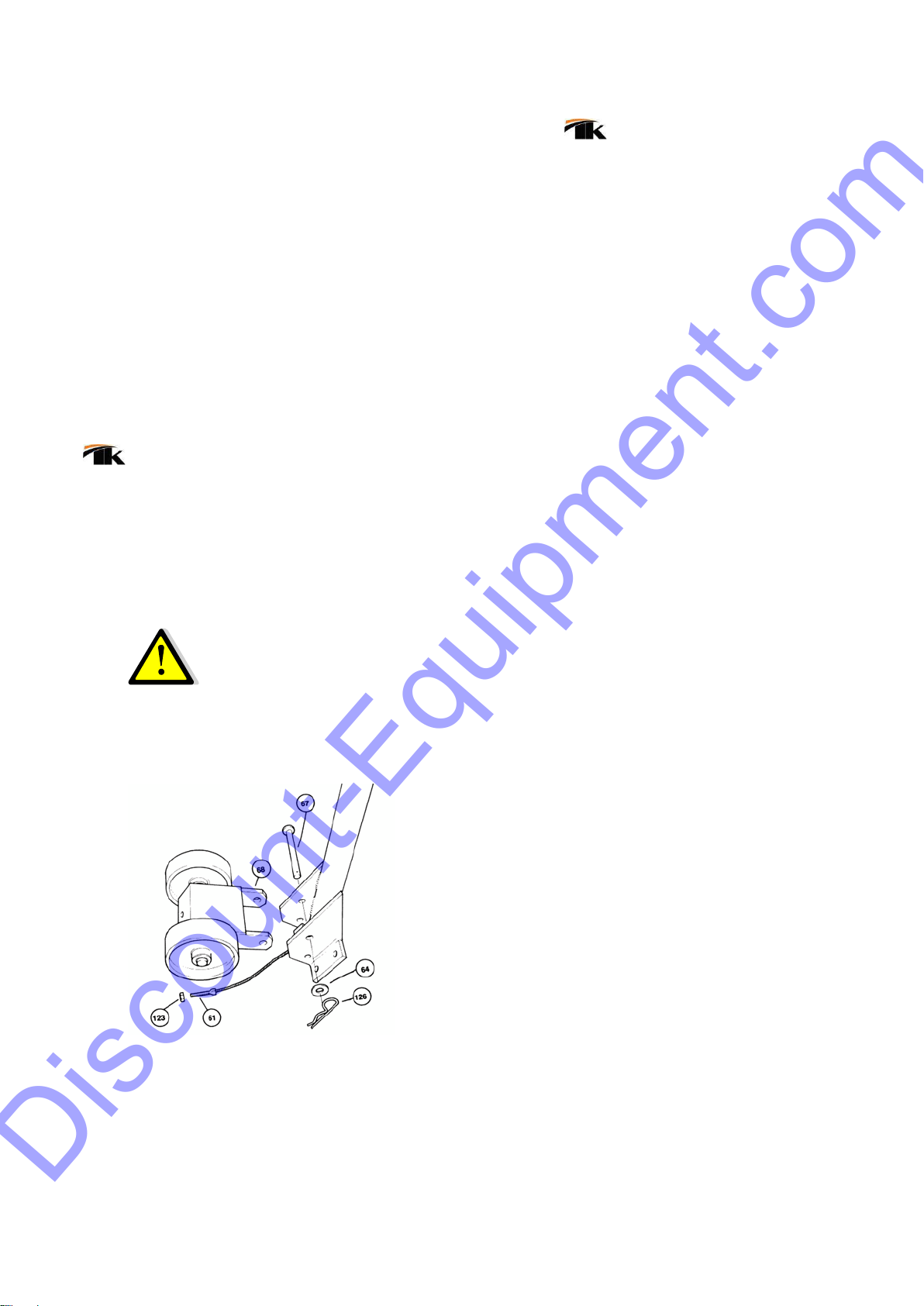
2. Remove the pin (67) from the handle assembly. Align the lift plate (68) and re-insert the top pin (67).
Place flat washer (64) on pin. Insert spring clip (126) through hole in pin. Feed threaded bolt end of
cable (61) through hole on lift plates.
Discount-Equipment.com

5
3. Tighten cable by attaching nut (123).
4. Remove the four bolts (70) and lock washers (69) from machine housing (104). Match up the holes on
the handle assembly to the machine housing and insert the bolts (70) and the washers (69).
Tightenbolts corner-to-corner. Before final tightening, place the machine on a flat surface to ensure all
wheels contact the surface.
EDGER ASSEMBLING/INSTALLATION
Make sure that the power source is disconnected; unplug the electric unit; disconnect spark plug and
turn off fuel supply on gas unit; disconnect air supply on air unit.
1. Tilt machine back onto handle (if your unit is equipped with a Honda GX engine, unit must be tilted
forward or cylinders will be flooded with oil).
2. Remove cutter cage and retainer shaft.
3. Facing underside of machine, slide dummy shaft (110) through outboard bearing on left side (if
engine is a Honda GX this will be on the right side of the housing).
4. Slide retainer shaft (108) through edger cage. The roll pin in the shaft head should fit into the slot
on the end plate of the cage.
5. Slide retainer shaft through the outboard bearing and the dummy shaft.
6. Using a 15/16” socket or wrenches tighten the retainer shaft by turning counter clockwise.
7. Install edger housing (106) using the three bolts supplied (107).
8. NOTE: Edger operation is not to be performed with main TFP cage in place.
Discount-Equipment.com

6
4. SAFETY PRECAUTIONS
READ AND STUDY THE FOLLOWING SAFETY INFORMATION BEFORE ATTEMPTING TO OPERATE THIS
EQUIPMENT. IN ADDITION, ENSURE THAT EVERY INDIVIDUAL WHO OPERATES OR WORKS WITH
THIS EQUIPMENT IS FAMILIAR WITH THESE SAFETY PRECAUTIONS.
WARNING - LETHAL EXHAUST GAS!
An internal combustion engine discharges carbon monoxide, which is a poisonous and odorless
invisible gas. Death or serious illness may result if inhaled. Operate only in an area with good
ventilation, NEVER IN A CONFINED AREA!
WARNING - DANGEROUS FUELS!
Use extreme caution when storing, handling and using fuels - they are highly volatile and explosive in
the vapor state. Do not add fuel while engine is running. Stop and cool the engine before adding fuel.
DO NOT SMOKE WHEN REFUELING!
SAFETY GUARDS
It is the owner's responsibility to ensure ALL GUARDS AND SHIELDS are in place and in working order.
IGNITION SYSTEMS
Breakerless magneto and batteries ignition systems CAN CAUSE SEVERE ELECTRICAL SHOCKS, avoid
contact with these components or their wiring.
SAFE DRESS
DO NOT WEAR loose clothing, rings, wristwatches, etc., near machinery.
NOISE PROTECTION
Wear O.S.H.A. specified hearing protection devices.
FOOT PROTECTION
Wear O.S.H.A. specified steel tip safety shoes.
HEAD PROTECTION
Wear O.S.H.A. specified safety helmets.
EYE PROTECTION
Wear O.S.H.A. specified eyes shields, safety glasses, and sweat bands.
DUST PROTECTION
Wear O.S.H.A. specified dust mask or respirator.
OPERATOR
Keep children and bystanders off and away from the equipment. Only trained Operators who fully
understand its safety operation must use this equipment.
For details on safety rules and regulations in the United States, contact your local Occupational Safety
and Health Administration (O.S.H.A.) office. Equipment operated in other countries must be operated
and serviced in accordance and compliance with any and all safety requirements of such country. The
publication of these safety precautions is done for your information does not by the publication of
these precautions, imply or in any way represent that these are the sum of all dangers present near
equipment. If you are operating a unit it is your responsibility to insure that such operation is
in full accordance with all applicable safety requirements and codes. All requirements of the United
Discount-Equipment.com
7
States Federal Occupational Safety and Health Administration Act must be met when operated in
areas that are under the jurisdiction of that United States Department.
5. SAFETY NOTICE & DECALS
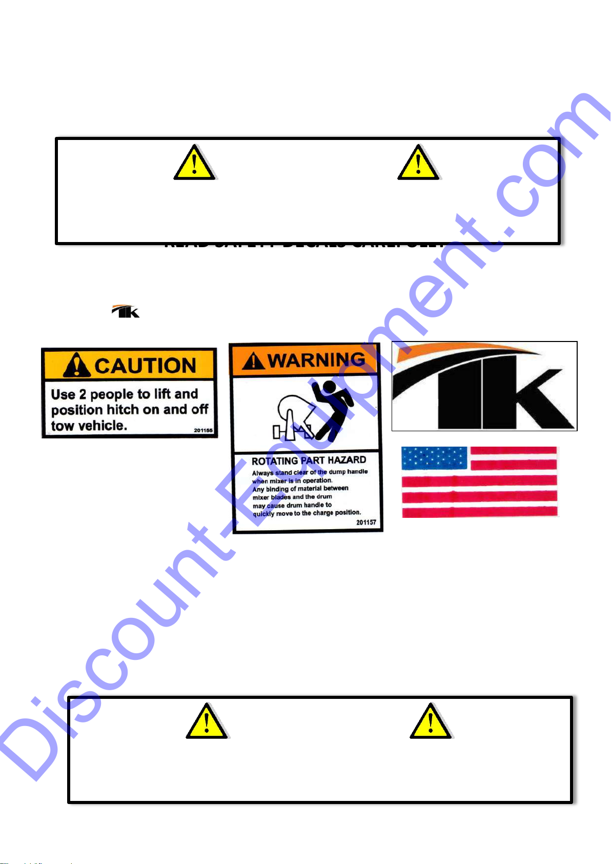
READ SAFETY DECALS CAREFULLY
Carefully read and follow all safety decals. Keep them in good conditions. If they become
aged, replace as required. If repainting, REPLACE ALL decals. Decals are available from your
authorized Distributors. Decals are not shown to scale.
201155
201157
IMPORTANT NOTICE
The "SAFETY ALERT SYMBOL" is used to call attention to items or operations that may be
dangerous to those operating or working with this equipment. These symbols can be found
throughout the manual and on the unit itself. Please read these warnings and cautions carefully.
IMPORTANT NOTICE
The "SAFETY ALERT SYMBOL" is used to call attention to items or operations that may be
dangerous to those operating or working with this equipment. These symbols can be found
throughout the manual and on the unit itself. Please read these warnings and cautions carefully.
Discount-Equipment.com

8
READ SAFETY DECALS CAREFULLY
Carefully read and follow all safety decals. Keep them in good condition. If they become aged,
replace as required. If repainting, REPLACE ALL decals. Decals are available from your
authorized Distributors. Decals are not shown to scale.
201003 (x2)
201005
201026
201152
201005
201006
201001 BIG
201001 SMALL
290791
201004
201154
Discount-Equipment.com

9
SAFETY PRECAUTIONS
!
DANGER
EXPLOSION HAZARD
Never operate the machine in an
explosive atmosphere, near
combustible materials or where
ventilation does not clear exhaust
fumes.
! WARNING
BURN HAZARD
Never come into contact with the
engine or muffler when engine is
operating or shortly after it is turned
off. Serious burns may occur
! CAUTION
MOVING PARTS
Before starting the machine ensure
that all guards and safety devices
are in place and functioning
properly.
! CAUTION
MACHINE DAMAGE
Advance cutter depth in small
increments to avoid premature
wear or damage.
! ATTENTION
READ OWNERS MANUAL
Read and understand operator's
manual before using this machine.
Failure to follow operating
instructions could result in serious
injury or death.
Discount-Equipment.com
10
6. BEFORE OPERATING
REMEMBER! It is the owner´s responsibility to communicate information on the safe
use and proper operation of this unit to the operators.
Before operating, review SAFETY PRECAUTIONS listed on page 6 of this manual.
Familiarize yourself with the operation of the unit and confirm that all controls
function properly BEFORE starting engine.
Locate the killing switch and assure you know how to STOP the unit.
Make sure hands, feet, and clothing are at a safe distance from any moveable parts
prior to starting.
Shrouds and guards are provided to protect the operator or structures in close
proximity to rotating hot engine parts. It is the RESPONSABILITY OF THE OPERATOR to
see that they are properly in place. NEVER operate this equipment without a guard.
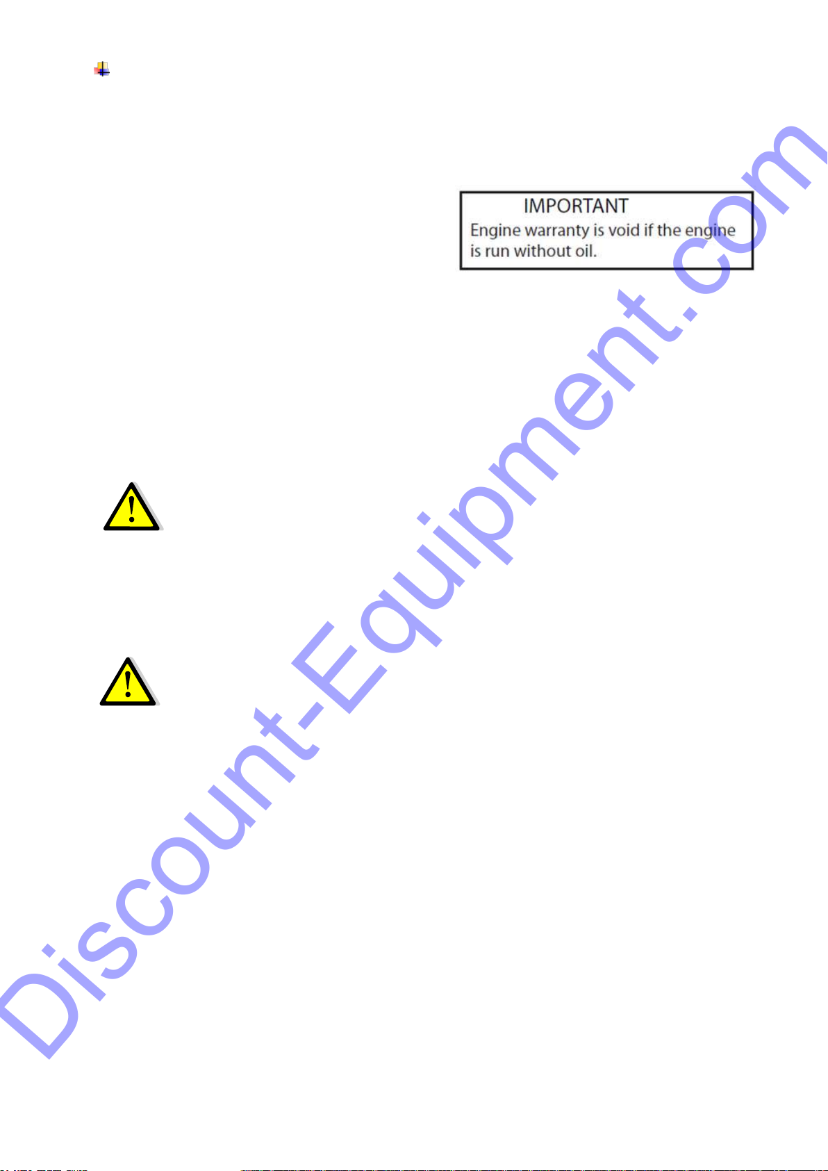
OIL LEVEL - Check the oil level in the engine. For more information see "Lubrication"
under the engine "Owner's Manual" the "Maintenance" section of this manual. All
Equipment come without oil, running an engine without lubrication may damage the
engine.
AIR CLEANER - Check to ensure elements are in good condition and properly installed.
Review every decal with the OPERATOR.
FUEL SUPPLY - Engines on equipment require an automotive grade of clean, fresh,
unleaded or regular gasoline. All equipment’s come without gasoline and oil.
FUEL FILTER - Check to ensure element is in good condition... Replace if it is clogged or
damaged.
LUBRICATION POINTS –Grease wheels (4), Drive Shaft and bushing daily. ALGO MAS?
SPARK PLUG (GAS UNIT) –Check and clean spark plugs regularly. A fouled, dirty or
carbonated spark plug may cause difficulties starting and poor engine performance.
Set spark plug gap to recommended clearance. Refer to engine manual.
BELT TENSION –If there is excessive belt play, there will be a decrease in the
cutting/grinding performance, which could cause unit damages. The normal belt play
should be 3/8” to 1/2” which is measured by depressing the top section of the belt at
the belt guard mounting bracket location. When adjusting the belts, make sure that
the drive pulley is in aligned with the cage pulley.
POSITION –The only operating position for this scarifier is at the rear of the
equipment. If the operator must leave this position the engine must be shut down.
Discount-Equipment.com
11
SPECTATORS –Keep all personnel/spectators away from the Scarifier while running.
This Spinning equipment can throw segments and can cause injuries.
7. STARTING ENGINE/AIR
GAS ENGINE
1. With the Scarifier engine level in the ground check oil level and add oil and fuel
as required.
2. Pull the stop switch on the unit to its "Out" position.
3. Prior to starting engine, raise the cutter cage assembly using the hand knob
lever, so that cutters do not touch the ground surface, "IDLE" POSITION, and
secure the lever with the locking handle
4. Move the engine throttle control to the "FAST" position.
5. Choke the engine if necessary. (You may not need to choke a warm engine)
BEFORE STARTING ENGINE MAKE SURE ALL GUARDS ARE IN PLACE.
6. Pull the starter string.
7. After the engine starts, move the choke lever to the open position, move the
throttle level to the "IDLE" position and let the engine warm-up for one or two
minutes.
SLOWLY LOWER CUTTERS INTO SURFACE, AND USE A DUST CONTROL
VACUUM TO PROVIDE A CLEAN WORKING AREA.
8. To stop the engine, make sure to let the engine idle before stopping by using
the crank lift handle to raise the scarifier cutters height.
9. Push in the engine stop switch on the scarifier.
10. Close the fuel valve.
ELECTRIC MOTOR
1. With the cage in maximum raised position, plug the motor into a suitable power
source.
2. Move the switch on the motor to the "ON" position.
3. It is recommended to let the motor idle before running and stopping by using
the crank lift handle to raise the scarifier cutters height.
Discount-Equipment.com
12
AIR SUPPLY
With cage in maximum raised position, attach air supply (minimum 90 C.F.M. at
90 P.S.I.) turn quick opening valve on. Run in for two (2) minutes. Turn off valve,
and then re-start.
The air regulator is equipped with a pressure gauge. The recommended operating
pressure is 90 P.S.I. at 90 C.F.M.; however when the unit is running with no load
(cutters not engaged) the gauge will read 40 P.S.I. When the cutters are engaged
the indicator needle should rise to 90 P.S.I
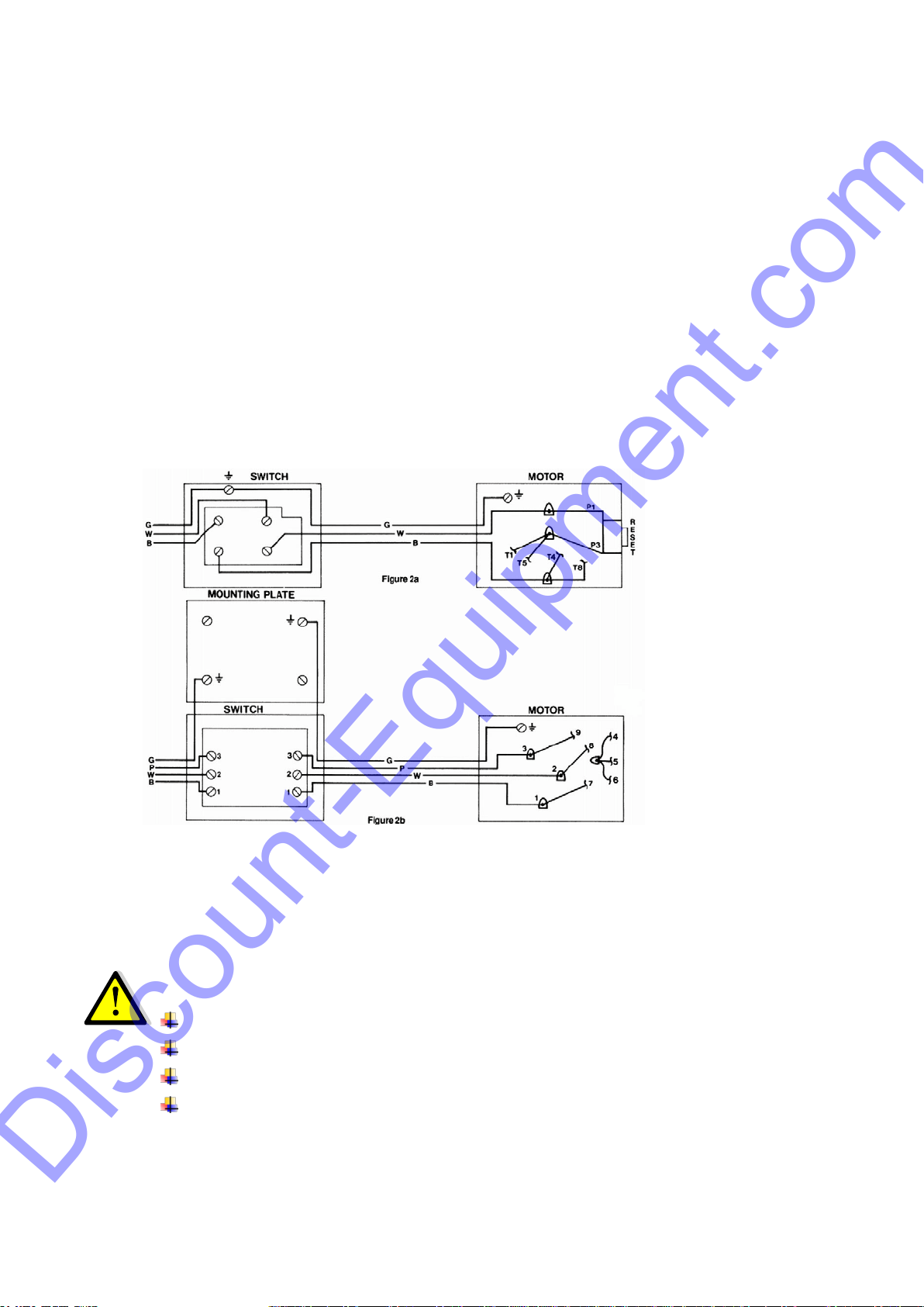
STOP/KILL-SWITCH INSTALLATION
On gas powered models, feed the attached kill switch with a wire coming all the way through the
engine terminal. Make sure to clamp the terminal with a pair of pliers
On electric models, attach bracket to the handle with screws and provided lock washers. Wire as
following figure:
2a diagram is for 220 volts and 2b diagram is for 440 volt.
STOPPING PROCEDURE:
With machine in upright position, adjust the cutter cage to maximum height by turning the height
adjustment knob to its farthest position. (This ensures clearance for the rotating cage.)
GASUNIT –Stop engine by depressing kill switch button located at top of handle.
ELECTRIC UNIT –Turn off switch on handle.
AIR UNIT –Turn off air supply valve.
STOP THE ENGINE OR ELECTRIC MOTOR BEFORE:
Adding fuel.
Leaving equipment unattended for any amount of time.
Making any repairs or adjustments to the unit.
Lifting/Transportation.
Discount-Equipment.com

13
8. OPERATION INSTRUCTIONS
OPERATING
1. After turning engine/motor “ON”, and the scarifier in its raised position, attach the air
supply (minimum 90 C.F.M. at 90 P.S.I.) turn quick opening valve on. Run in for two
(2) minutes. Turn valve off, and then re-start. The air regulator is equipped with a
pressure gauge. The recommended operating pressure is 90 P.S.I. at 90 C.F.M.;
however when the unit is running with no load (cutters not engaged) the gauge will
read 40 P.S.I. When the cutters are engaged the indicator needle should rise to 90
P.S.I.
1. Lower scarifier cutters until it just touches the pavement by turning the manual lift
crank clockwise.
NEVER FORCE THE CUTTERS HEAD INTO THE SURFACE TO A POINT WHERE THE
EQUIPMENT STARTS BOUNCING
2. Slowly push scarifier forward to desired area.
This Unit can be used as several applications, make sure you know the operation
procedure of this equipment and the cutters types for each application
TYPICAL SCARIFIER APPLICATIONS
Asphalt leveling and grooving
Carpet backing removal
Coating removal
Concrete grinding
Concrete & steel surface preparation
Concrete grooving
Epoxy removal
Expansion joint leveling
Floor cleaning steel & concrete
Glue/adhesive removal
Milling joints
Non-slip removal
Paint removal
Steel de-scaling
Traffic line removal
Wheelchair ramp leveling.
Discount-Equipment.com

14
9. RECOMMENDED CUTTERS TYPE SELECTION
ADHESIVES –CARPET R120 (B-1 Cutters)
Most carpets adhesives removal
Estimated Production Rate: 100-300 sq.ft/hr. Estimated Cutter Life: 1200-1500 sq.ft.
ADHESIVES –TILE R138 (A-3, B-3 Cutters)
Most tile adhesives removal.
Estimated Production Rate: 100-250 sq.ft/hr
Estimated Cutter Life: 1200-1500 sq.ft
CONCRETE GRINDING
R150, R151, or R152 (Carbide Cutters)
Smoothing rough concrete and/or grinding high spots.
Estimated Production Rate: 200-500 sq.ft/hr.
Estimated Cutter Life: 3000-6000 sq.ft
CONCRETE SCARIFYING/GRINDING R134 or R139 (Tungsten Carbide Tipped Cutters)
Concrete preparation prior coating application or concrete overlay (1/8” depth of cut per pass.)
Estimated Production Rate: 200-400 sq.ft/hr.
Estimated Cutter Life: 8000-15,000 sq.ft
PAINTING LINES REMOVAL R132 (B-2)
Painting concrete/asphalt lines removal
Estimated Production Rate: 10-20 linear ft/min
Estimated Cutter Life: 800-2000 linear ft.
THERMOPLASTIC LINES REMOVAL R143 (B-3)
Thermoplastic concrete/asphalt base paints
Estimated Production Rate: 10-20 linear ft./min
Estimated Cutter Life: 800-1200 linear ft.
10. SERVICE INSTRUCTIONS
Never service or lubricate the unit engine while running.
After servicing the unit, restore and fasten all guards, shields, and covers to their
original positions.
Never drain oil into the ground, into open streams, or down sewage drains.
Keep air filter clean at all times. Wash away dust and debris using anon-oil based
cleaning solvent. Let the filter dry before re- installing.
WHEN LIFTING/LOWERING ALWAYS:
1. Set the machine in an upright position and adjust the cutter cage to maximum
height by turning the height adjustment knob to its farthest position. (This will
ensure clearance for the rotation cage.)
2. Stop the engine or electric motor.
3. REMOVE CUTTERS.
Discount-Equipment.com

15
4. Lift the cutting guide to avoid any contact with the head.
5. Secure any other hardware on the machine.
6. Make sure you use appropriated lifting equipment to lift equipment.
7. Do not position yourself where you could possibly be pinched / caught between
the equipment and some other obstacle.
TOWING
1. Move Scarifier on the jobsite by hand pushing. Do not tow the unit with another
vehicle. The scarifier may be damage if towed.
CUTTING
1. Must know what you are machine, before making any cuts. Be aware of all
utilities i.e. gas/pipe lines, electricity, etc. take necessary precautions to prevent
injury /death.
STORING
1. Drain fuel tank.
2. Clean drive shaft and coat parts with grease.
3. Lube all bearings
4. Empty water system
5. Clean all moving parts with WD-40 lubricant.
6. Lower unit completely.
7. Cover unit for protection.
ENGINE
See engine owner´s manual maintenance schedule.
LUBRICATION
1. Grease wheels, and knob lever daily. Use high quality gun grease.
2. Keep a coating of grease on the drive shaft and threads for easy installation or
removal and longer bushing life.
SPARK PLUG
Discount-Equipment.com

16
1. Check and clean spark plugs regularly. A fouled, dirty or carbonized spark plug
causes hard starting and poor engine performance. Set spark plug gap to
recommended clearance. Refer to engine manual.
BELT TENSION
1. If there is excessive belt play, there will be a decrease in the cutting/grinding
action, which could cause cage and machine damage. The normal belt play
should be 3/8” to 1/2” which is attained by depressing the top section of the
belt at the belt guard mounting bracket location. When adjusting the belt make
sure that the drive pulley is in alignment with cage pulley. Tighten all engine
mount bolts, adjust the two engine-stop bolts, and tighten lock nuts.
CUTTER CAGE REMOVAL/CHANGE
1. Make sure that the power source is disconnected. With gas models turn off fuel
supply to engine and disconnect sparkplug; unplug electric unit; disconnect air
supply on air unit.
2. Tilt machine back onto the handle. (If your unit is equipped with a Honda GX
engine, unit must be tilted forward to change cutters or cylinders will be
flooded with oil).
3. Facing the underside of the machine housing (figure 3-A) place a bar between
the cutter rods to jam cage C.
4. Remove end cap and with a 1” (26 mm) socket loosen and remove the shaft
by turning in clockwise direction or remove end cap and shaft guard to insert a
drift pin into the hole on the main shaft B and turn shaft clockwise to loosen and
remove shaft.
5. Disengage the cage from the drive pins by moving to the left. (The cage on the
Honda GX machines will move to the right). Remove cage.
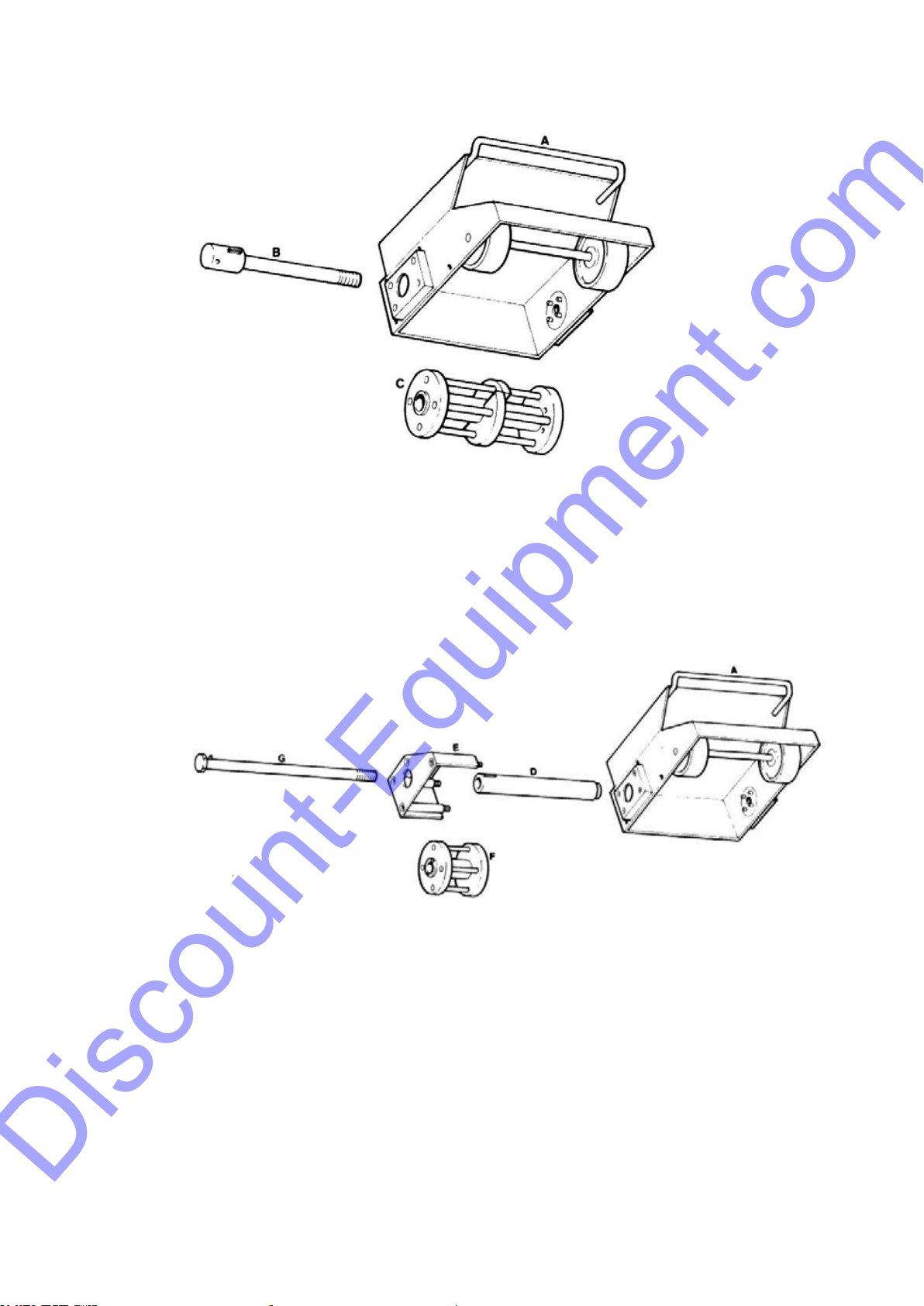
EDGER CAGE REMOVAL
1. Make sure that the power source is disconnected. With gas models turn off fuel
supply to engine and disconnect sparkplug; unplug electric unit; disconnect air
supply on air unit.
2. Tilt machine back onto handle. (If your unit is equipped with a Honda GX
engine, unit must be tilted forward to change cutters or cylinders will be
flooded with oil).
3. Using a 15/16” socket or wrench, turn head of shaft (G) clockwise to loosen.
4. While turning the shaft outwards, cage will move towards the outer edge as
well. Free cage from locking pins on shaft by pushing cage back towards main
housing (A). Turn shaft out and move.
Discount-Equipment.com
17
5. Cage will be free to remove from edger.
Figure 3A
CHANGING CUTTERS/SHAFTS
1. Once the cage has been removed use a 5/32” Allen Key and 7/16” open end
wrench, remove screws and cover plate from cage. With drift pin tap rods from
the drive side until free of cage. Replace cutters or shafts as required. Replace
cover plate. To re-install cutter cage in machine, reverse procedure for removal.
Ensure that the shaft is tight.
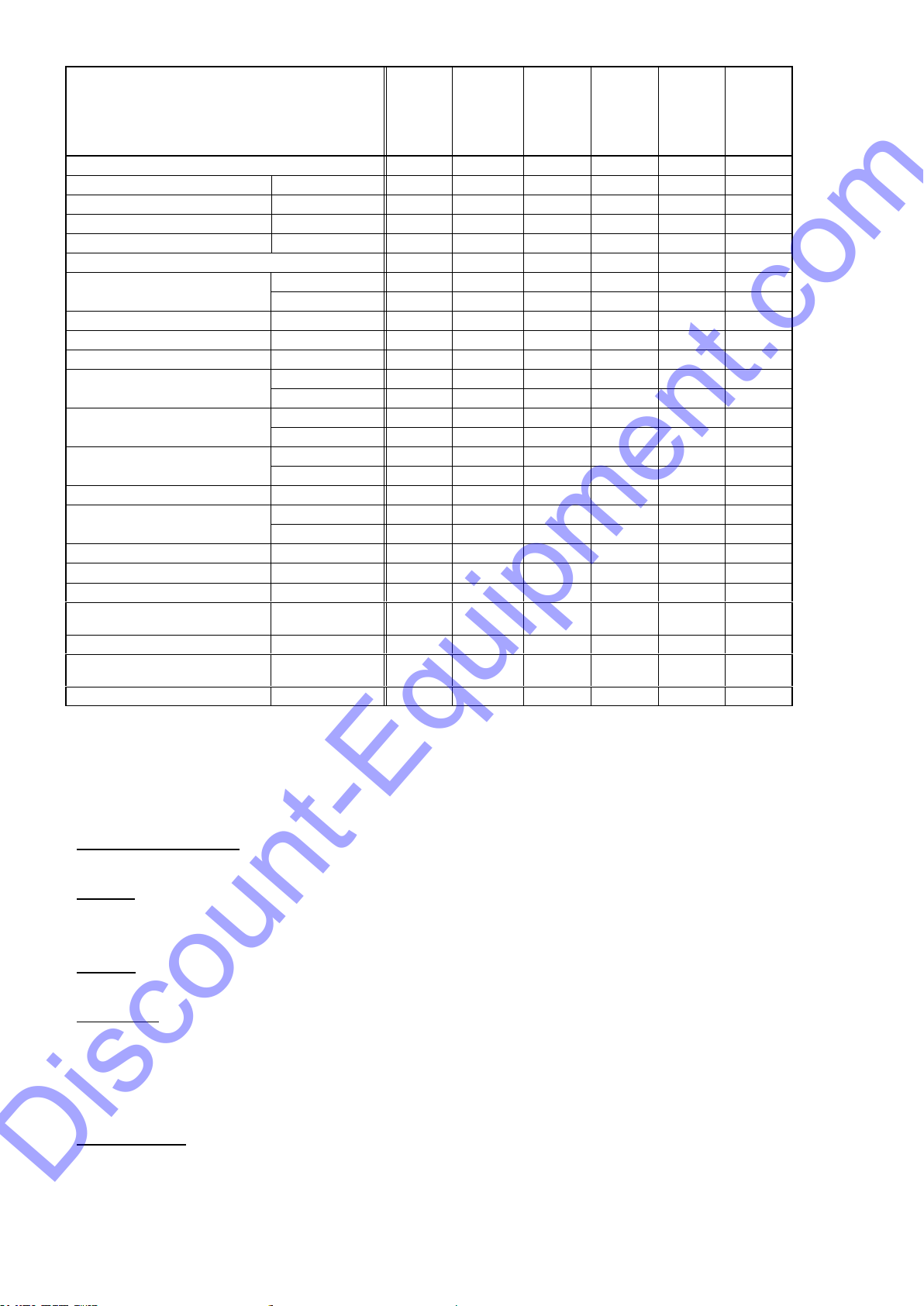
11. MAINTENANCE SCHEDULE
1. Check all hardware after the first 5 hours of use, the follow the maintenance schedule.
Discount-Equipment.com
18
Maintenance
Services Intervals
After
every use
After 45
days or
50 hrs.
Every 3
months
or
100 hrs.
Every 6
months
or
200 hrs.
Every 9
months
or
300 hrs.
Every 12
months
or
400 hrs.
General Inspection:
Guards
Check
X
X
X
X
X
Warning stickers
Check
X
X
X
X
X
Wheels
Check operation
X
X
X
X
X
X
Test run
Check operation
X
X
X
X
X
Engine:
Engine oil
Check level
X
X
X
X
X
X
Change
X
X
X
Engine oil filter
Replace
X
X
Oil cooler
Clean
X
X
X
X
Cooling Fins
Clean
X
X
X
X
X
Air cleaner
Check - clean
X
X
X
X
X
X
Replace
X
Air Intake Line
Check
X
Replace
2 years
Fan Belt
Check tightness
X
X
Replace
500 hrs.
Valve clearance
Check-adjust
X
X
Fuel filter
Check & clean
X
X
X
X
Replace
X
X
Fuel Tank
Clean
500 hrs.
Engine wiring
Check
X
Cage:
Teeth: (see Individual Cage for
specifications)
Check wear
X
X
X
X
X
X
Change
Shaft: (see Individual Cage
for specifications)
Check wear
X
X
X
X
X
X
Change
12. REPLACEMENTS
Parts
Tolerance or Replacement Cycle
Engine Components
Refer to your engine manufacturer´s Owner´s
Manual
V-Belts
Replace if stretched to the point that the idler does
not work properly. Replace the V-belts if they are
cracked or torn.
Cutters
Replace if Cutters present any missing segments or
stress cracks.
Hardware
Re-torque all bolts after the first eight hours of
operation and check hardware every 25 hours.
Replace any worn or damaged hardware as
needed. Replacement hardware should be grade 5
and zinc plated.
Safety Decals
Replace if they become aged, damaged or cannot
be easily read.
Discount-Equipment.com

19
13. TORQUE CHART
Discount-Equipment.com
Table of contents


