TKR Group 83 30 5 A87 F94 Repair manual

R1-23.12-V7
83 30 5 A87 F94
Disassembly and assembly tool
Translation of the original owner's manual

2

3
This owner's manual is protected by copyright. Any use beyond the restrictions imposed by copyright legislation undertaken without the permission of the manufacturer is
illegal and punishable by law. This also applies to the extraction of individual illustrations and use of texts as excerpts.
1. Safety
1.1 General instructions 4
1.2 Explanation of symbols 5
1.3 Scope of supply 6
1.4 Safety instructions 7
2. Technical data
2.1 Technical data 9
2.2 Device components 11
3. Startup
3.1 Intended use 12
3.2 Working with the tool - basic principles 13
3.3 Commissioning and safe handling 14
4. Use
4.1 Preparatory work 16
4.2 Removing the stator winding from a mild hybrid
transmission 17
4.3 Installing a stator winding in a mild hybrid
transmission 22
4.4 Removing the stator winding from a plug-in
hybrid transmission 26
4.5 Installing a stator winding in a plug-in hybrid
transmission 35
4.6 Transmission assignments for centering and
adjusting the tool 42
4.7 Completing an operation and tool storage 42
5. Maintenance
5.1 Troubleshooting 43
5.2 Regular inspection and maintenance 44
6. Service
6.1 Disposal 45
6.2 Warranty and service 45
6.3 Declaration of conformity 46
EC Declaration of conformity 47

4
1.1 General instructions
State-of-the-art
This tool is state-of-the-art technology. To ensure that the
equipment operates safely, it must be operated in a proper and
safety-conscious manner.
Technical changes
In the interests of quality assurance, we reserve the unrestricted
right to carry out technical changes as a result of further
technological developments and product improvements without
prior notification.
Reading the owner's manual
Before using the tool, make sure you read the owner's
manual carefully and understand it. This manual must
always be available where the product is used.
Handling
All the actions necessary to ensure correct operation are
described in the owner's manual. Any working methods other
than those approved by the manufacturer are prohibited.
Faults
If faults occur, the operator may only eliminate those faults
through their own actions where the corresponding remedy
is described.
Warranty
The manufacturer accepts no liability for damage or injury caused
by improper repair or the use of third-party replacement parts.
No warranty will be provided for damage caused to the device
due to the tool being used incorrectly.
Environment
Make sure that the tool is set up in a work area which is free from
corrosive liquids, greases and oils.
Declaration of Conformity
The tool has been manufactured and inspected in
compliance with European directives.The Declaration
of Conformity is included with this owner's manual.
Risk of damage to the tool
The tool must only be used as described in the
instruction manual. It is expressly forbidden to misuse
the tool or to use it for any other purpose. Please make
sure that you and your staff handle the tool correctly.
Risk of damage to the tool
The tool is designed for max. 16000 applications
according to specification EN 13155:2020.
Risk of injury
In addition to the owner's manual and the binding
provisions of the accident prevention regulations
which apply in the country and at the place of use,
you must also comply with the general (accepted)
rules for safe and professional working.
Technical personnel
Only trained and instructed personnel are authorized to carry
out the repair/maintenance work on the vehicles and vehicle
components concerned.
These personnel must also be able to prove that they have
participated in further training which enables them to carry out
the particular activities which are required for this tool.
6.3
5
XX Nm
13
12
T25
1.2 Explanation of symbols
Follow the manual
Follow the general instruc-
tions
Wear protective gloves
Wear safety shoes
Warning!
General source of danger
Warning!
Fingers could become
trapped
Warning
Magnetic field
Warning!
Hands could become trapped
Warning! Danger from
electrical voltage
Pacemaker-wearers prohibited
Please note the...
For more information, see
section …
Hexagon, width across flats
Allen screw, size
Torx, size
Arrow showing direction
Turn clockwise
Turn counterclockwise
Observe the torque
CE symbol
UK Conformity Assessment
Some sections in this instruction manual use internationally recognised warning symbols, warning notes and general in-
struction symbols.
The individual symbols are explained below. Follow all the instructions and safety rules.

6
1
2
3
8
83 30 5 A87 F94
4
5
6
7
83 30 5 A87 FB1
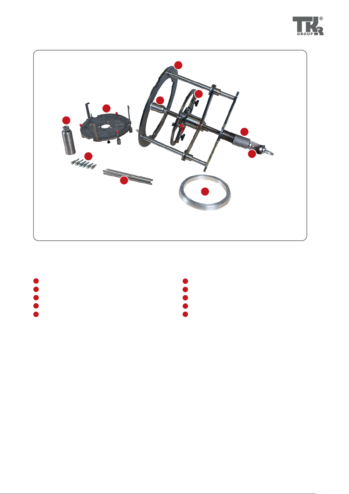
1.3 Scope of supply
Item Designation pc.
1Disassembly and assembly tool with lifting eye (83 30 5 A87 F94_A), lifting plate (83 30 5 A87 F94_C), and spacer
(83 30 5 A87 F94_D) 1
2Hexagon screws with centering sleeves 6
3 Owner’s manual German/ English 1
4 USB stick with foreign language versions of the owner's manual 1
5 Spacer 2 long (83 30 5 A87 FB1_B) 3
6 Lifting plate 2 (83 30 5 A87 FB1_A) 1
7 Centering pins 3
8 Centering ring 1
7
1.4 Safety instructions
The tool is strictly approved solely for the purpos-
es for which the manufacturer has designed it.
The tool must only be used for the activities described in this own-
er's manual. Never use the tool for anything but its intended pur-
pose. Safety is no longer guaranteed if the tool is used incorrectly.
This tool may only be used to dismantle a BMW-approved trans-
mission
CAUTION
If used with the wrong accessories, this may cause
material damage and bodily injury.
Not using original tools and original accessories will result in
a high risk to safety.Only original accessories and accessories
which have been approved by BMW may be used (see BMW
workshop manual). Only use with the screws provided..
No modifications may be made to the tool. The manufacturer is
not liable for conversions or modifications of the tool which are
not described in this manual or for any damage to material or
personal injury resulting from such conversions or modifications.
CAUTION
A falling load may cause material damage and bod-
ily injury.
Falling loads may cause serious injuries or damage to material.
Check and make sure that the load has been suspended correct-
ly before raising it.
CAUTION
Risk of material damage and bodily injury
You must read and understand the safety instructions before
carrying out the repair.
Not reading the instructions may result in serious bodily injury.
Wear safety shoes (according to ISO 20345, S2).
Wear protective gloves to prevent cut injuries.
CAUTION
Danger of crushing and serious injuries
Position hands and feet away from where there is a risk of
crushing. Only use the tool on an even, dry, horizontal floor of
sufficient load-bearing capacity.
CAUTION
Risk of material damage and bodily injury
Personnel who have not been trained or not been instructed
are prohibited from using the tool. The tool must not be lent to
untrained persons.
Ensure that the tool is only operated by trained personnel who
are instructed in its use!
Ensure that the owner's manual is made available
to the operating personnel.
Each operator must carefully read and understand this owner's
manual before using the tool for the first time. This manual must
always be available at the site where the product is used.
Follow the workshop manual from BMW AG.
Workshop manuals must be referred to under all
circumstances.
Observe the applicable national regulations for
the prevention of accidents.
In addition to the owner's manual and the binding provisions of
the accident prevention regulations which apply in the country
of use, you must also comply with the general, accepted rules for
safe and professional working.
Pay attention to the nameplate and the labelling
on the tool. The tool and the labels on it must be
inspected visually every time before use.
Never throw the tool or allow it to fall.
8
When lifting and lowering the load, avoid bump-
ing into obstacles.
Using the device to carry people or climbing on
the raised load is not permitted.
CAUTION
Risk of material damage and bodily injury
Make sure that there is sufficient light.
Make sure that there is sufficient space for working.
If any abnormality is identified, the tool must not be used.
Please contact Service ( 6.1).

9
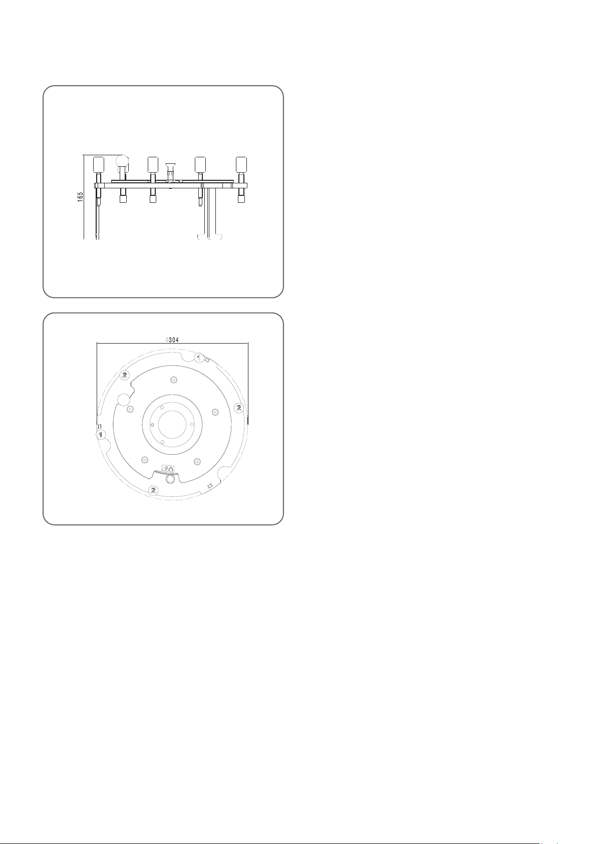
2.1 Technical data
Disassembly and assembly tool
Product type Disassembly and assembly tool
Item number 83 30 5 A87 F94
Weight 32 kg
Max. Dimensions (W x H) in mm 450 x 725 mm
Ambient temperature -20°C to +60°C/ -4°F to 140°F
front left
top Disassembly and assembly tool 83 30 5 A87 F94
(with lifting eye 83 30 5 A87 F94_A, lifting plate 1 83 30 5
A87 F94_B, and spacer 1 83 30 5 A87 F94_C)
Width: 450 mm
Min. height: 675 mm
Max. height: 725 mm
10
front
top
Accessory kit: Lifting plate 2
83 30 5 A87 FB1_A
Width: 450 mm
Min. height: 675 mm
Max. height: 725 mm
11
A1
2.2.1
A2
K
H
E
G
F
D
C
B
2.2 Device components
2.2.1 Disassembly and assembly tool
Spindle with square 8 AF
Adjustment nut
Lifting plate 1
Baseplate
Spacer 1 (short)
A1
A2
B
Hexagon screws with centering sleeves
Lifting plate 2
Spacer 2 (long)
Centering pins
Centering ring
C
D
E
F
G
H
K
12
3.1 Intended use
The disassembly and assembly device 83 30 5 A87 F94 is designed exclusively for install-
ing and removing the transmission cover and stator winding from a BMW AG mild hybrid
transmission for which it has been approved. The accessory kit 83 30 5 A87 FB1 can be used
to convert the device for installing and removing the stator winding from BMW AG plug-in
hybrid transmissions for which it has been approved.
Make sure that everything is clean when working. Only place transmission components on
suitable receptacles. Objects must not be allowed to get into the transmission.
Raising or lowering the tool is prohibited while people are in the danger zone of the load.
Standing beneath the load while it is being lifted or lowered is prohibited.
The operator may only initiate a raising or lowering operation once he has satisfied himself
that the tool is properly secured.
Undoing the screws of the tool while it is under load is forbidden.
Lifting the loaded tool without securing it by attaching it to the workshop crane is
forbidden.
Consult the manufacturer before using the tool in specific atmospheres (high humidity,
salty, acidic or basic).
The tool is suitable for use at ambient temperatures between -20 °C and +60°C.
The load must be raised/ lowered slowly and carefully.
CAUTION
Risk of material damage and bodily injury
If the tool shows any defects, it must be taken out of use immediately.
This tool must only be used for processing the transmissions for which it has been approved
(see workshop manual).
The tool is only suitable for installing/removing the transmission components from
the BMW AG transmissions for which it has been approved, as described in this oper-
ating manual and must only be used on minor transport routes.
Use as described in
instruction manual
Incorrect use

13
3.2 Working with the tool - basic principles
Risk of injury
The tool must be positioned so there is no risk of
crushing.
Stable positioning
The tool may only be used on a level, horizontal floor.
Warranty
The manufacturer accepts no liability for damage
caused by repairs which have been carried out
incorrectly.
Using the tool incorrectly so that the equipment
is damaged will invalidate the warranty.
Only use with the screws provided.
14
3.3.23.3.1
3.3 Commissioning and safe handling
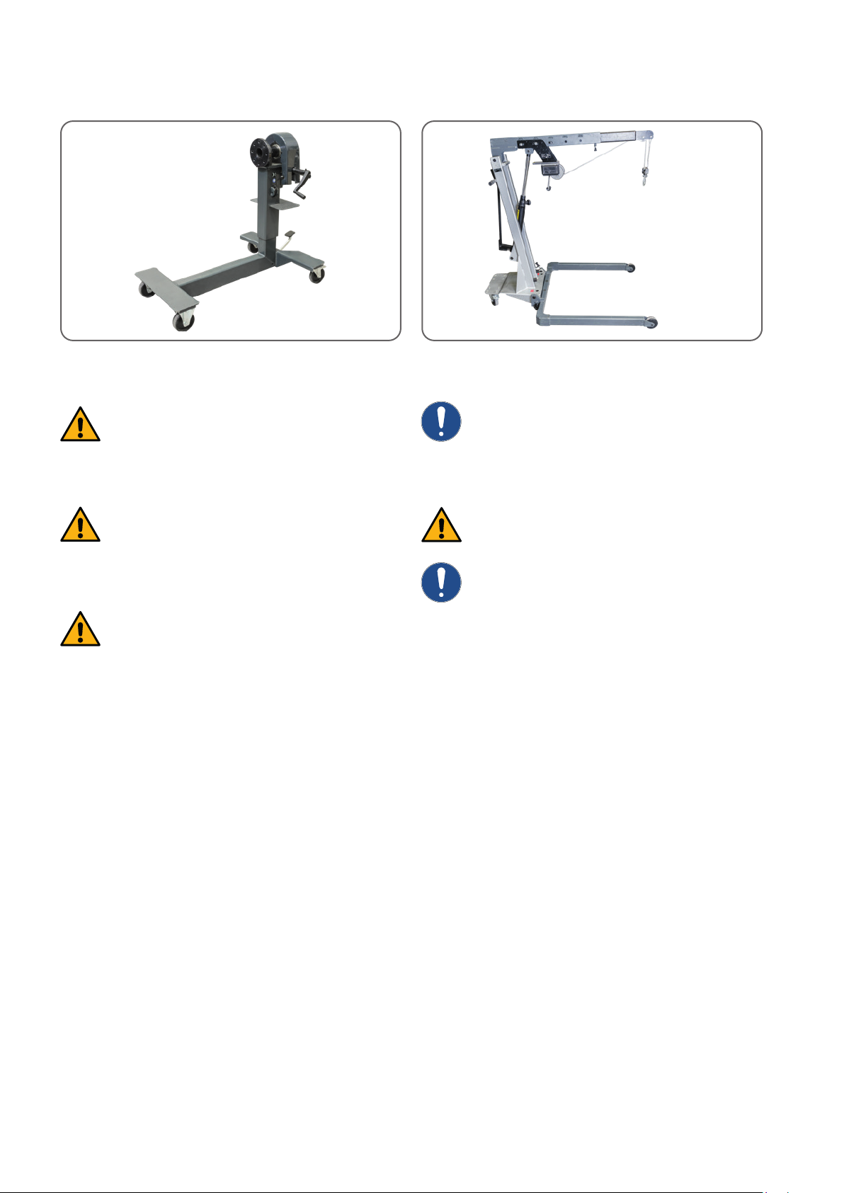
3.3.1 Engine and transmission mount 00 2 300
CAUTION
Risk of injury
Do not exceed the permissible lifting weight of the
engine and transmission mount.
CAUTION
Risk of injury
Exceeding the load-carrying capacity on the engine
and transmission mount may invalidate the CE mark
CAUTION
Risk of injury
Watch the engine and transmission mount and the
load during all movements.
3.3.2 Workshop crane WW-DHZ-1000
Lifting and lowering the transmission components
is only permissible using the workshop crane
WW-DHZ-1000 with the rope hoist attachment
WW-AFA-600 (83 30 5 A33 E60).
Do not exceed the permissible load carrying capacity
of the workshop crane.
Watch the workshop crane and load during all movements.

15
3.3.3 3.3.4
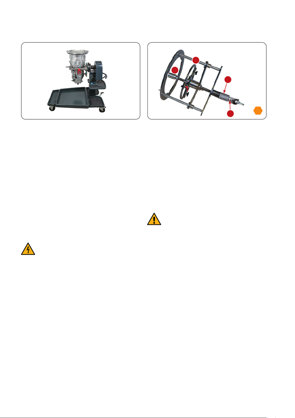
3.3.3 Support 83 30 5 A82 CC8
CAUTION
Risk of damage to aterial and personal injury
Take into account the permissible nominal load of
the support.
See the operating manual for the support.
3.3.4
Two persons are required to operate the crane and to adjust
and attach the tool.
Two persons are required to remove the tool from the packaging.
16
A1
B
A2
D
8
4.1.14.1.1 4.1.24.1.2
4.1 Preparatory work
4.1.1
Carry out the following activities before removing the transmis-
sion cover and the stator winding from either the mild hybrid
or plug-in hybrid transmissions (Follow BMW workshop manual):
• Attach the support 83 30 5 A82 CC8 to the transmission
(see owner’s manual 83 30 5 A82 CC8)
• Install the transmission with the support 83 30 5 A82 CC8 on
the engine and transmission holder 00 2 300 (see owner’s
manual 83 30 5 A82 CC8) and rotate the transmission 90°
(transmission cover faces up)
• If not available: Attach the rope hoist attachment WW-
AFA-600 to the workshop crane WW-DHZ-1000 (see owner’s
manual WW-AFA-600)
• Drain the transmission oil (see BMW AG workshop manual)
CAUTION
Danger from electrical voltage
Before starting work, make sure that everything is
voltage-free and dead.
4.1.2
Move the spacer 1 [short, D] to the top positon by turning the
adjustment nut [A2] counterclockwise in order to avoid damag-
ing the end of the shaft. Move the lifting plate 1 [B] to the top
position. Turn the spindle clockwise [A1] with a suitable tool on
the spindle hexagon (8 AF).
Please note: you move the spacer [D] by turning the knurled ad-
justment nut [A2] and you move the lifting plate 1 [B] by turning
the spindle hexagon [A1].
CAUTION
Risk of personal injury
Risk of crushing at the top end of the spindle.
17
4.2.44.2.4
12
T25
4.2.14.2.1 4.2.24.2.2
4.2.34.2.3
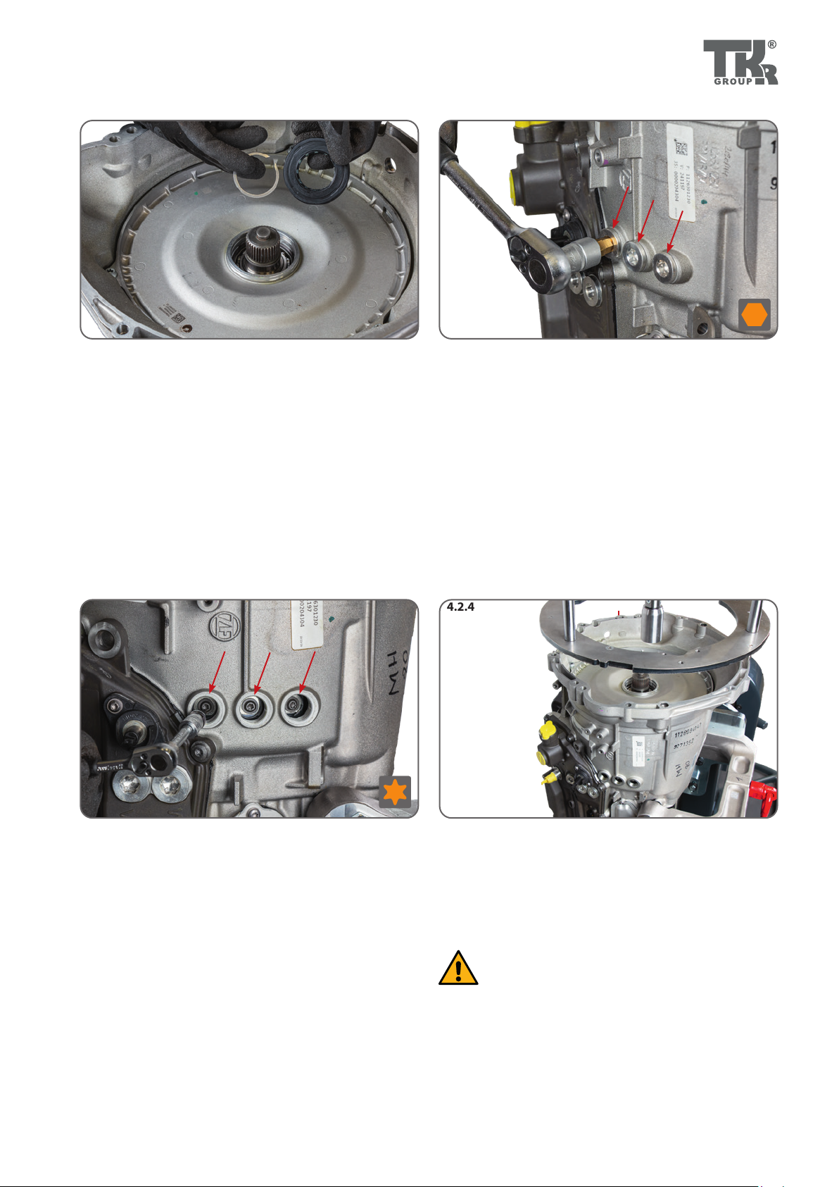
4.2.3
Remove the connecting screws of the three pole contacts (T 25).
4.2.4
Use the workshop crane WW-DHZ-1000 to place the tool 83 30 5
A87 F94 over the transmission. Align the slot in the baseplate [C]
for the middle and left pole contact of the stator winding.
CAUTION
Risk of damage to materia
Make sure that the spacer 1 [D] and the lifting plate 1
[B] are at the top (follow Step 4.1.2).
4.2 Removing the stator winding from a mild hybrid
transmission
4.2.1
Remove the radial shaft seal (RWDR) using a suitable tool
(83 30 5 A85 A86). Remove the snap ring with a suitable tool
(83 30 5 A82 CE3).
4.2.2
Remove the cover screws for the three pole contacts of the stator
winding (12 mm Allen key).

18
13 1515 NmNm
D
A2
4.2.54.2.5 4.2.64.2.6
4.2.74.2.7 4.2.84.2.8
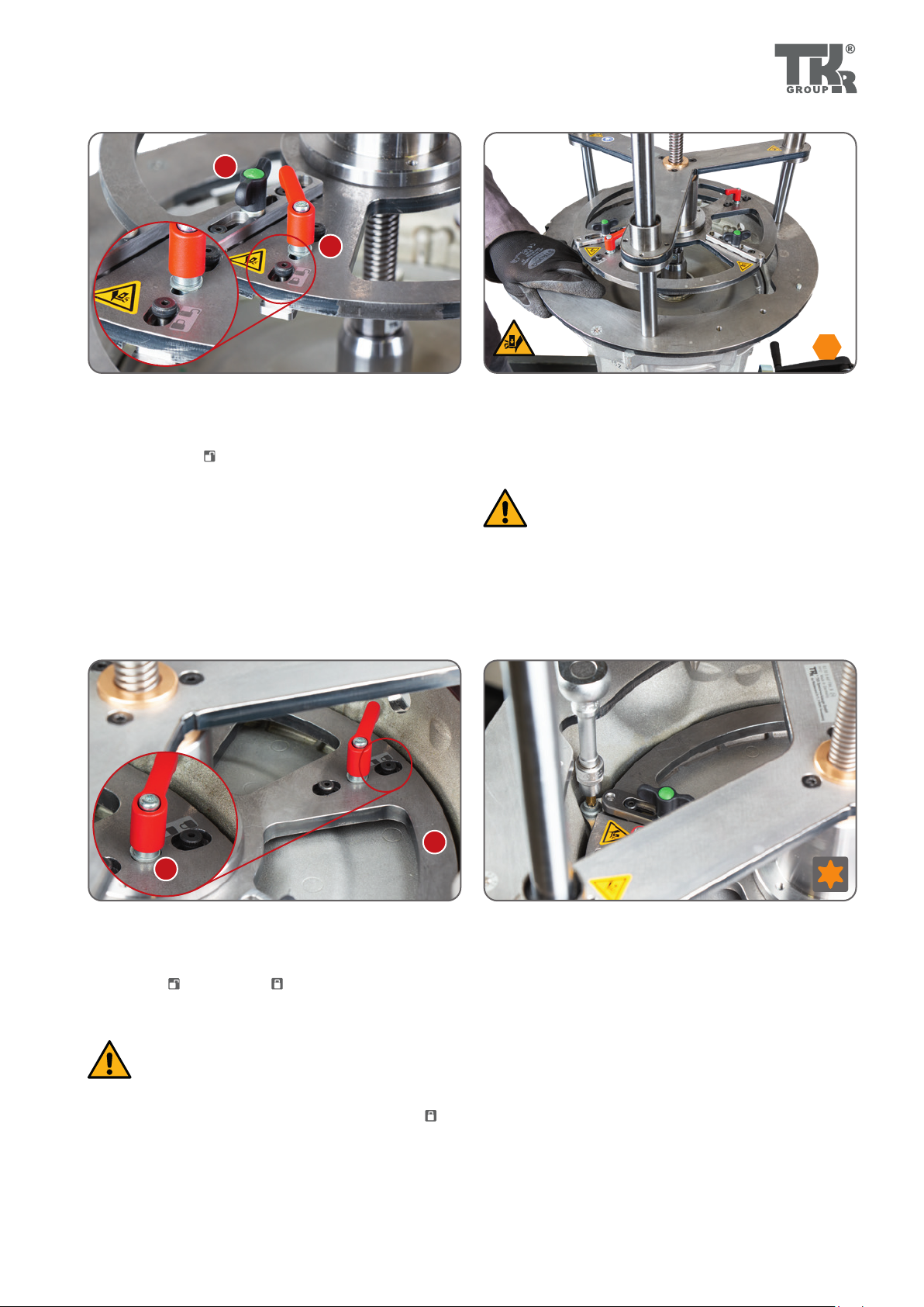
4.2.5
Lower the tool 83 30 5 A87 F94 onto the case flange. When cen-
tering, one of the centering pins P1, P2 or P3 aligns with one of
the flange holes (see Chapter 4.6).
4.2.6
Screw the baseplate [C] of the tool to the transmission flange
with three of the hex screws [E]. Make sure that the diameter of
the red or blue sleeves is suitable for the holes in the transmis-
sion flange (see Chapter 4.6). The torque setting is 15 Nm.
4.2.7
The tool is now seated in the center on the transmission flange.
The shaft end of the transmission is in line with the longitudinal
axis of the spacer 1 of the tool [D].
4.2.8
Lower the spacer 1 [D] onto the shaft end by turning the adjust-
ment nut [A2] until you feel resistance.
19
7
T40
B1
B2
B
B1
8
4.2.94.2.9 4.2.104.2.10
4.2.114.2.11 4.2.124.2.12
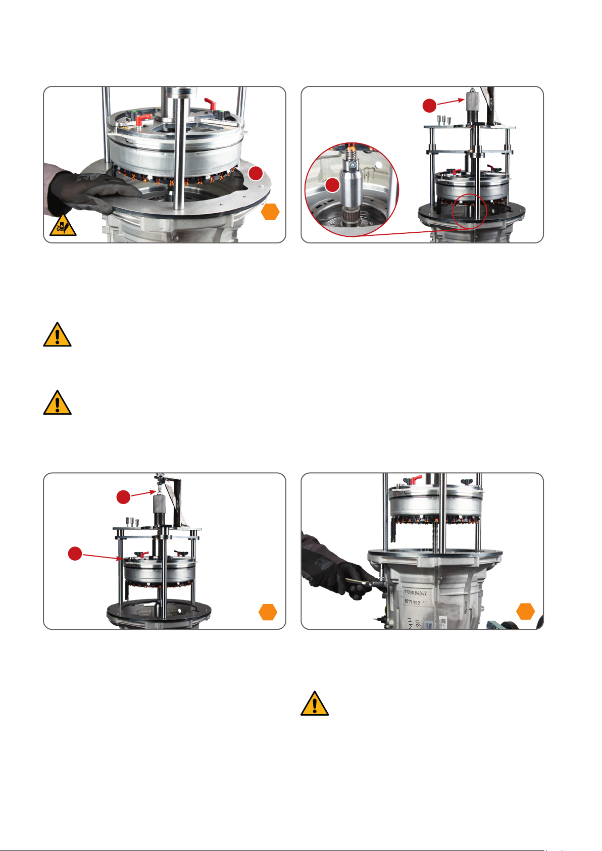
4.2.11
After lowering the lifting plate 1 [B], push the two clamping lugs
[B1] from the position to the position and screw them tight
with the red handle.
CAUTION
Risk of material damage and bodily injury
You may only lift the lifting plate 1 [B] after the two
clamping lugs have been pushed into position and
screwed tight.
4.2.12
Undo the three screws of the transmission cover using a suitable
tool (T40).
4.2.9
Before lowering the lifting plate 1 [B], check that the two clamp-
ing lugs [B1] are in position and all the positioning lugs [B2]
are withdrawn.
4.2.10
Lower the lifting plate 1 [B] onto the transmission cover by turn-
ing the hexagon on the spindle [A1](8 mm AF).
CAUTION
Risk of personal injury
Do not place your hands on the baseplate of the tool.
Risk of crushing! Only one person in the working area.
20
7
13
D
A2
C
B
A1
8
max. 10max. 10 NmNm
8
4.2.134.2.13 4.2.144.2.14
4.2.154.2.15 4.2.164.2.16
4.2.15
Raise the lifting plate 1 [B] to the top end position by turning the
hexagonal of the spindle [A1].
4.2.16
Undo the three hex screws between the baseplate [C] and
transmission flange.
CAUTION
Risk of material damage and bodily injury
The tool must be secured with the workshop crane
before undoing the hexagonal screws.
4.2.13
Lift the transmission cover by turning the spindle hexagon [A1]
clockwise until the fixed winding can be seen approximately above
the baseplate [C]. Use a suitable tool (8 AF, max. torque 10 Nm).
CAUTION
Risk of material damage and bodily injury
Before lifting, ensure that the three screws of the
pole contacts are undone (Steps 4.2.2/4.2.3).
CAUTION, risk of personal injury
Do not place your hands on the baseplate [C] of
the device. Risk of crushing! Only one person in the
working area.
4.2.14
Lift the spacer 1 [D] by turning the adjustment nut [A2]. The
spacer 1 [D] must hang freely above the shaft end.
This manual suits for next models
1
Table of contents
Other TKR Group Tools manuals


Popular Tools manuals by other brands


Central Pneumatic
Central Pneumatic 68293 Owner's manual & safety instructions

Power Fist
Power Fist 8843799 manual

parktool
parktool BBT-9 instructions

Thomas&Betts
Thomas&Betts Stakon COMFORT CRIMP ERG4005 Instructions for use

Central Pneumatic
Central Pneumatic 97014 Set up and operating instructions

Power Fist
Power Fist 8536609 user manual


