BLACKHAWK! ROKEN 1000K User manual

BST1000KM3L
REV : FEB 2010
INSTRUCTIONS MANUAL
(ORIGINAL INSTRUCTIONS)
NOTICE D’INSTRUCTIONS
(NOTICE ORIGINALE)
BETRIEBSANLEITUNG
(ORIGINALBETRIEBSANLEITUNG)
ROKEN 1000K
Part Number : BST1000K
Référence : BST1000K
Bestellnummer : BST1000K

_________________________________________ROKEN 1000_____________________________________
2

_________________________________________ROKEN 1000_____________________________________
3
Page
I) WARNINGS – MISES EN GARDE – WARN INWEISE -6
1) BEFORE AND DURING USE – AVANT ET PENDANT L’UTILISATION – VOR UND WÄ REND DER BENUTZUNG -6
2) DURING USE – PENDANT L’UTILISATION – WÄ REND DER BENUTZUNG -6
3) AFTER USE – APRES UTILISATION – NAC DER BENUTZUNG -6
) MAINTENANCE – POUR LA MAINTENANCE – WARTUNG -6
II) DESCRIPTION OF THE GRINDER AND THE STANDARD ACCESSORIES
DESCRIPTION DE L’AFFUTEUSE ET DE SES ACCESSOIRES STANDARD
BESC REIBUNG VON SC LEIFMASC INE UND STANDARDZUBE ÖR
7
1) DESCRIPTION OF PARTS – DENOMINATION DES COMPOSANTS – BEZEIC NUNG DER TEILE 7
2) TECHNICAL SPECIFICATIONS – SPECIFICATIONS TECHNIQUES – TEC NISC E MERKMALE 7
III) OPERATING – UTILISATION – BENUTZUNG 8
1) ADJUSTMENT – REGLAGE – EINSTELLUNG 8
2) FIRST GRINDING – PREMIER AFFUTAGE – ERSTES SC LEIFEN 9
3) SECOND GRINDING – DEUXIEME AFFUTAGE – ZWEITES SC LEIFEN 10
) ADJUSTMENT OF THE STROKE OF THE HEAD OF SUPPORT 2, POINT ANGLE
AJUSTEMENT DE LA COURSE DE LA TETE DU SUPPORT 2, ANGLE DE POINTE
EINSTELLUNG DER ANSC LAGTIEFE DES ALTERUNGSKOPFES 2, SPITZENWINKEL
11
IV) MAINTENANCE – MAINTENANCE – WARTUNG 12
1) REPLACING THE GRINDSTONE – REMPLACEMENT DE LA MEULE – AUSWEC SELN DER SC LEIFSC EIBE 12
2) CLEANING – NETTOYAGE – REINIGUNG 12
3) CONTROL – CONTROLE – KONTROLLE 12
V) SPARE PARTS – PIECES DE RECHANGE – ERSATZTEILE 13
1) EXPLODED VIEW – VUE ECLATEE – EXPLOSIONSZEIC NUNG 13
2) PART NUMBERS AND DESCRIPTIONS – REFERENCES ET DENOMINATION DES PIECES –
BESTELLNUMMERN UND BEZEIC NUNG DER TEILE
1
TABLE OF CONTENTS – TABLE DES MATIERES –
IN ALTSVERZEIC NIS

_________________________________________ROKEN 1000_____________________________________
4
1) BEFORE AND DURING USE
•Wea p otective glasses to avoid any metal p ojections.
•Wea a espi ato y mask to avoid inhaling metal pa ticles.
•Check you clothes and ectify them if necessa y. The e must be no isk fo them to be caught by the machine.
(Tie, sleeves, etc.)
•Wea a cap if you hai is long.
2) DURING USE
DANGER!
•Keep you face at a easonable distance f om the g indstone.
•Do not put any fo eign bodies o you hands in contact with the g indstone.
•Do not place anything between the p otective housing and the g indstone.
CAUTION!
•Do not use the Roken 1000 g inde fo any othe wo k than the sha pening of spot welde d ills.
•In the event of any unusual noise o smell, stop the machine and unplug it.
3) AFTER USE
DANGER!
•Neve fo ce the g indstone to stop otating. Always let it slow down g adually on its own.
4) MAINTENANCE
•Always emove the plug of the Roken 1000 f om the socket.
I) Wa nings
You Roken
10
00 wo ks on 220/230 Volt, single phase, 50 Hz cu ent. Howeve , befo e using it, you a e
equi ed to
connect a plug with ea th to the wi e.
The yellow and g een ea th wi e must always be connected fo safety easons.
Green / Yellow
Blue
Brown

_________________________________________ROKEN 1000_____________________________________
5
1) AVANT ET PENDANT L’UTILISATION
•Utilisez des lunettes de protection pour vous préserver des éventuelles projections métalliques.
•Portez un masque respiratoire pour éviter d’inhaler des poussières métalliques.
•Contrôlez et, si nécessaire, rectifier vos vêtements afin qu’ils ne puissent être happés par la meule. (Cravate,
manches, etc.)
•Mettez une casquette pour retenir vos cheveux s’ils sont longs.
2) PENDANT L’UTILISATION
DANGER !
•Gardez votre visage à une distance convenable de la meule.
•Ne pas mettre en contact avec la meule des corps étrangers ou vos doigts.
•Ne rien introduire entre le carter de protection et la meule.
ATTENTION !
•Ne pas employer l’affûteuse Roken 1000 pour une autre utilisation que l’affûtage des forets à découper les points
de soudure.
•En cas de bruit anormal ou d’odeur inhabituelle, arrêtez et déconnectez immédiatement la fiche de la prise
d’alimentation électrique.
3) APRES UTILISATION
DANGER !
•Ne jamais freiner brutalement la rotation de la meule. Il faut toujours la laisser s’arrêter seule.
4) POUR LA MAINTENANCE
•Avant toute opération de maintenance, toujours déconnecter la fiche électrique du Roken 1000 de la prise
d’alimentation.
I) Mises en garde
Dès réception, le Roken
1000
est prêt à l’emploi.
Cependant, pour le connecter sur une ligne
220/230 Volt
s monophasé
50 z, vous devez fixer à l’extrémité du câble d’alimentation, une fiche correspondant aux prises de votre installation
électrique.
Le fil vert/jaune correspond à la terre, il doit toujours être connecté pour des raisons impératives de sécurité.
Vert / Jaune
Bleu
Marron

_________________________________________ROKEN 1000_____________________________________
6
1) VOR UND WÄ REND DER BENUTZUNG
•Tragen Sie eine Schutzbrille zum Schutz vor möglichen Metallspritzern.
•Tragen Sie eine Atemmaske, um keinen Metallstaub einzuatmen.
•Überprüfen Sie ihre Kleidung und ändern Sie sie gegebenenfalls. Die Kleidung darf nicht von der Schleifscheibe
erfasst werden. (Krawatte, Ärmel, u.s.w.)
•Tragen Sie eine Kappe, falls Sie lange aare haben.
2) WÄ REND DER BENUTZUNG
GEFAHR!
•Gehen Sie mir Ihrem Gesicht nicht zu nahe an die Schleifscheibe heran.
•Berühren Sie die Schleifscheibe weder mit irgendwelchen Fremdkörpern noch mit Ihren änden.
•Bringen Sie nichts zwischen Schutzgehäuse und Schleifscheibe.
ACHTUNG!
•Der Schleifer Roken 1000 darf ausschließlich zum Schärfen von Punktschweiß-Bohren benutzt werden.
•Bei ungewöhnlicher Geräusch- oder Geruchentwicklung schalten Sie die Maschine sofort ab, und ziehen Sie den
Netzstecker.
3) NAC DER BENUTZUNG
GEFAHR!
•Bremsen Sie die Rotation der Schleifscheibe niemals mit Gewalt ab. Sie muß immer von selbst allmählich zum
Stillstand kommen.
4) WARTUNG
•Vor jeder Wartungsarbeit stets den Netzstecker ziehen.
I) Warnhinweise
Sofort nach Eintreffen / Anlieferung ist der Roken
1000
einsatzbereit.
Um den Roken
1000
an einen 220/230 Volt, 1 pin,
50 z anschließen zu können, befestigen Sie an das Ende des Anschlusskabels einen passenden Stecker. Das
grün/gelbe Kabel (Erde) muß aus Sicherheitsgründen immer angeschlossen werden.
Grün / Gelb
Blau
Braun

_________________________________________ROKEN 1000_____________________________________
7
1) DESCRIPTION OF PARTS – DENOMINATION DES COMPOSANTS – BEZEIC NUNG DER TEILE
2) TECHNICAL SPECIFICATIONS – SPECIFICATIONS TECHNIQUES – TEC NISC E MERKMALE
Point angle – Angle d’affûtage – Zuschärfungwinkel 180°
Clea ance angle – Angle de dégagement – Öffnungswinkel 5°
G indstone – Meule – Schleifscheibe ø 121, CBN 170
Moto – Moteur – Motor 65 W
Rotation – Vitesse de rotation – Rotationsgeschwindigkeit 2850 rpm
Powe
Alimentation électrique
Elektrik
AC, 230V, 50/60 Hz
Courant alternatif, 230V, 50/60 Hz
Wechselstrom, 230V, 50/60 z
Weight – Poids – Gewicht 8 kg
Dimensions – Dimensions – Abmessungen 185 x 210 x 230 mm
Noise level – Niveau sonore – Geräuschpegel < 70 dB
Accesso ies – Accessoires – Zubehör D ill holding cylinde s – Cylindres de maintien – altezylinder
ø 8.0, ø 8.2, ø 9, ø 10.0
Holde ing – Bague de guidage – Führungsring
Allen key – Clé Allen - Spannschlüssel
II) Desc iption of the g inde and the standa d accesso ies
Description de l’affûteuse et de ses accessoires
Beschreibung von Schleifmaschine und Standardzubehör
Suppo t 2: point angle
Support 2 : angle de pointe
alterung 2: Spitzenwinkel
Elect ic moto
Moteur électrique
Elektromotor
4 holding cylinde s
cylindres de maintien
4 altezylinder
Allen key
Clé de serrage
Spannschlüssel
Holde ing
Bague de guidage
Führungsring
Adjustment suppo t
Gabarit de réglage
Einstellvorrichtung
Plastic
p otective
plate
Glace plastique de protection
Kunststoff-Schutzscheibe
Metal p otective housing
Carter métallique de protection
Metall-Schutzgehäuse
Diamond g indstone
Meule diamantée
Diamantschleifscheibe
Suppo t 1 sha pening angle
Support 1 d’angle d’affûtage
alterung 1: Zuschärfungswinkel
On/Off switch
Interrupteur
Schalter
Moulded base
Base moulée
Formsockel

_________________________________________ROKEN 1000_____________________________________
8
1) ADJUSTMENT – REGLAGE – EINSTELLUNG
1:
Choose the holde cylinde co esponding to the size of the d ill to be sha pened.
Prendre le cylindre de maintien correspondant au diamètre du foret à affûter.
Wählen Sie den altezylinder entsprechend dem Durchmesser des zu schleifenden
Bohrers.
2:
Inse t the holde cylinde into the adjustment suppo t until it touches the stop.
Introduire le cylindre dans le gabarit de réglage. Le mettre en appui sur la butée.
Stecken Sie den Zylinder dis zum Anschlag in die Einstellvorrichtung.
3:
Push the d ill into the holde cylinde as fa as it will go. Tu n it to the ight until it
stops. Hold the d ill fi mly. Secu e the d ill in the holde cylinde using the Allen key.
Introduire le foret dans le cylindre de maintien, le mettre en appui et le
tourner à droite jusqu’à ce qu’il bute en position. Effectuer le serrage du
foret dans le cylindre avec la clé Allen en le maintenant en position.
Stecken Sie den Bohrer so weit wie möglich in den Zylinder, drehen Sie ihn nach
rechts bis er anstößt. alten Sie den Bohrer fest; mit dem Inbus-Schlüssel ziehen
Sie den Bohrer im Zylinder fest.
DANGER / DANGER / AC TUNG
When secu ing the d ill in the holde , make su e that the sc ew does not land in a g oove
of the d ill.
La vis de blocage ne doit pas serer dans une rainure du foret.
Die Feststellschraube darf nicht in eine Rille des Bohrers klemmen.
Note: Fo sho t d ills, the end of the holde cylinde with the sc ew is
inse ted fi st into the adjustment suppo t.
Note: Pour les forets courts, le cylindre est introduit dans le gabarit de
réglage par le côté vis.
Anmerkung: Beim kurzen Bohren wird der Zylinder mit der Schraubenseite in
die Einstellvorrichtung gesteckt.
:
Place the holde ing a ound the cylinde and d ill. Push it until it is ight up
against the adjustment suppo t. Tu n it to the ight until it knocks against the
stop. Fasten the sc ew with the Allen key.
Mettre en place la bague de guidage sur le cylindre de maintien. La mettre
en appui contre le gabarit de réglage. La tourner à droite en arrêt contre
l’ergot. Serrer la vis avec la clé Allen.
Setzen Sie den Führungsring auf den altezylinder. Drücken Sie ihn bis an die
Einstellvorrichtung. Drehen Sie ihn nach rechts bis zum Anschlag. Ziehen Sie
die Schraube mit dem Inbusschlüssel fest.
III) Ope ating – Utilisation – Benutzung

_________________________________________ROKEN 1000_____________________________________
9
2) FIRST GRINDING – PREMIER AFFUTAGE – ERSTES SC LEIFEN
5:
Switch the machine on to sta t the otation of the g indstone.
Appuyer sur l’interrupteur pour la mise en rotation de la meule diamantée.
Betätigen Sie den Schalter, um die Rotation der Diamant-Schleifscheibe zu starten.
6:
Inse t the holde + d ill + holde ing in suppo t 1 (sha pening angle), so that the
d ill is in contact with the g indstone.
The stop (pin) on the oute side of suppo t 1 must go into one of the two g ooves
on the holde ing.
Introduire le cylindre de maintien, assemblé au foret, dans le support 1
d’angle d’affûtage.
L’ergot de la face extérieure du support d’angle d’affûtage doit entrer dans
une des 2 rainures de la bague de guidage.
Stecken Sie den mit den Bohrer zusammengesetzten Zylinder in die alterung 1,
Zuschärfungswinkel.
Der Anschlag (Zapfen) an der Außen Seite von alterung 1 muß in eine der beiden
Kerben des Führungsrings einrasten.
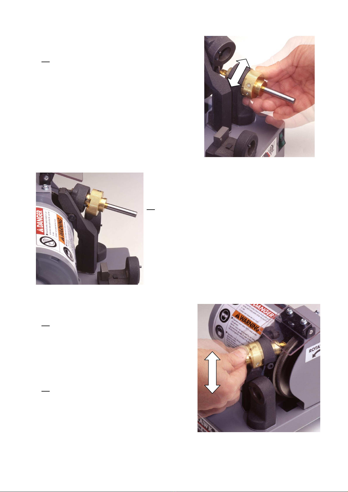
7:
Hold the holde ing against suppo t 1. Tu n the holde ing left and ight as fa
as the pin will allow you. Repeat this until you cannot hea the g inding noise
any longe .
Faites pivoter la bague de guidage à droite et à gauche à fond contre la
butée, en la maintenant délicatement poussée jusqu’à ce qu’elle prenne
appui contre la face extérieure du support 1 d’angle d’affûtage. (Au bruit,
vous entendez quand la meule n’est plus en contact avec le foret)
alten Sie den Führungsring gegen die alterung 1. Drehen Sie ihn nach
rechts und links so weit es der Anschlagzapfen zulässt. Am Geräusch hören
Sie, wenn die Schleifscheibe nicht mehr in Kontakt mit dem Bohrer ist
8:
Pull the holde , d ill and holde ing assembly slightly away f om suppo t.
Retirez légèrement l’assemblage foret, cylindre et bague de l’ergot du
support d’angle d’affûtage.
Ziehen Sie alter, Bohrer und Führungsring leicht aus der alterung 1 heraus.
9:
Give the whole combination a ½ tu n (180°) until the stop (pin) fits into
the second of the two g ooves on the holde ing.
Faire pivoter l’ensemble de 180° pour introduire la butée dans la
deuxième encoche de la bague de guidage.
Drehen Sie alles um 180° bis der Anschlag (Zapfen) in die zweite der
beiden Kerben des Führungsringes passt.
180°

_________________________________________ROKEN 1000_____________________________________
10
10:
Hold the holde ing against suppo t 1. Tu n the holde ing left and ight as fa
as the pin will allow you. Repeat this until you cannot hea the g inding noise
any longe .
Faites pivoter la bague de guidage à droite et à gauche à fond contre la
butée, en la maintenant délicatement poussée jusqu’à ce qu’elle prenne
appui contre la face extérieure du support 1 d’angle d’affûtage. (Au bruit,
vous entendez quand la meule n’est plus en contact avec le foret).
alten Sie den Führungsring gegen die alterung 1. Drehen Sie ihn nach
rechts und links so weit es der Anschlagzapfen zulässt. Am Geräusch hören
Sie, wenn die Schleifscheibe nicht mehr in Kontakt mit dem Bohrer ist.
3) SECOND GRINDING – DEUXIEME AFFUTAGE –
ZWEITES SC LEIFEN
11:
Inse t the holde , d ill and holde ing assembly into suppo t 2 (point angle).
One of the two g ooves on the holde ing must fit ove the two pins on the
oute face of suppo t 2.
Introduire l’assemblage foret, cylindre, bague dans le support 2 angle de
pointe; une des rainures de la bague de guidage doit chevaucher les
deux butées de la face du support 2 d’angle de pointe.
Stecken Sie Bohrer, altezylinder und Führungsring in die alterung 2
Spitzenwinkel. Eine der beiden Kerben am Führungsring muß über die beiden
Zapfen an der Außenseite der alterung 2 greifen.
12:
Tip the head of suppo t 2 down until it comes to est against the g indstone.
B ing it back to its o iginal position.
Faire basculer doucement la tête du support 2 vers le bas jusqu’à ce
qu’elle vienne en butée. Laisser revenir la tête à sa position de départ.
Kippen Sie den Kopf der alterung 2 leicht nach unten bis zum Anschlag.
Dann lassen Sie den Knopf in die Ausgangsposition zurückgehen
13:
Pull the holde , d ill and holde ing assembly slightly away f om suppo t 2.
Retirer légèrement l’assemblage foret, cylindre, bague pour le
dégager des butées du support 2.
Ziehen Sie den Bohrer, altezylinder und Führungsring leicht aus der
alterung 2 heraus.

_________________________________________ROKEN 1000_____________________________________
11
1 :
Give the composition a ½ tu n (180°), until the 2 pins fit into the
second of the two g ooves on the holde ing.
Faire pivoter l’assemblage de 180°, les butées du support 2
doivent être introduites dans la 2
ème
encoche de la bague de
guidage.
Drehen Sie alles um 180° bis die beiden Zapfen in die zweite der
beiden Kerben des Führungsringes passen.
15:
Tip the head of suppo t 2 down until it comes to est against the g indstone.
B ing it back to its o iginal position.
Faire basculer doucement la tête du support 2 vers le bas jusqu’à ce
qu’elle vienne en butée. Laisser revenir la tête à sa position de départ.
Kippen Sie den Kopf der alterung 2 leicht nach unten bis zum Anschlag.
Dann lassen Sie den Kopf in die Ausgangsposition zurückgehen.
16:
Switch the machine off to stop the otation of the g indstone.
Appuyer sur l’interrupteur pour stopper la rotation de la meule.
Schalten Sie die Maschine aus, um die Rotation der Schleifscheibe zu
stoppen.
17:
Using the Allen key, dismantle the holde , d ill and holde ing assembly and
emove the d ill which is eady fo use.
Avec la clé Allen, démonter l’assemblage bague / cylindre pour retirer
le foret qui est prêt pour une nouvelle utilisation.
Mit dem Inbusschlüssel nehmen Sie altezylinder, Bohrer und Führungsring
auseinander, der Bohrer ist nun gebrauchsfertig.
4) ADJUSTMENT OF THE STROKE OF THE HEAD OF SUPPORT 2, POINT ANGLE.
AJUSTEMENT DE LA COURSE DE LA TÊTE DU SUPPORT 2, ANGLE DE POINTE.
EINSTELLUNG DER ANSC LAGTIEFE DES ALTERUNGSKOPFES 2, SPITZENWINKEL
This adjustment allows the ope ato to get a fine point on the d ill.
Cet ajustement permet d’obtenir une pointe de guidage du foret plus ou moins fine.
Diese Einstellung ermöglicht es, eine feinere Spitze des Bohrers zu erzielen.
1
Loosen the 8mm nut
Desserer l’écrou 8mm.
Mutter M8 öffnen.
2 Twist the sc ew towa ds A o B
Tourner la vis dans le sens A ou B.
Schraube in Richtung A oder B verdrehen.
3 Fasten the nut
Resserrer l’écrou.
Mutter anziehen.
180°

_________________________________________ROKEN 1000_____________________________________
12
1) REPLACING THE GRINDSTONE – REMPLACEMENT DE LA MEULE –
AUSWEC SELN DER SC LEIFSC EIBE
1
Loosen the 3 sc ews with a 3mm hexagon w ench (not supplied) and emove the g indstone’s metal housing.
Dévisser les 3 vis de fixation du carter métallique à l’aide d’une clé Allen de 3mm (non fournie).
Entfernen Sie die 3 Befestigungsschrauben vom Metall-Schutzgehäuse mit einem 3mm Inbusschlüssel (ist nicht im Lieferumfang).
2
Put the 13mm spanne on the shaft of the moto to maintain the shaft into place
and emove the 3 sc ews with a 5mm w ench (see pictu e).
Maintenir l’arbre du moteur à l’aide d’une clé de 13mm et enlever les 3 vis
avec une clé de 5mm. (Voir photo)
Die Motor-Achse mit ilfe von einem 13 mm Inbusschlüssel aufrechterhalten
und die 3 Schrauben mit einem 5mm Inbusschlüssel entfernen. (Siehe Foto)
3
Remove the old g indstone and install a new one.
Enlever l’ancienne meule et installer la nouvelle.
Entfernen Sie die alte Schleifscheibe und setzen Sie die neue richtig ein.
Maintain the shaft of the moto with the 13mm spanne and fasten the 3 sc ews equally.
Maintenir l’arbre du moteur avec la clé de 13 mm et serrer les 3 vis.
Die Motor-Achse mit einem 13 mm Inbusschlüssel aufrechterhalten und die 3 Schrauben festdrehen.
5
Replace the p otective housing and fasten the sc ews.
Remettre le carter de protection et serrer les vis.
Setzen Sied as Metall-Schutzgehäuse wieder ein, und ziehen Sie die Schrauben fest.
2) CLEANING – NETTOYAGE – REINIGUNG
•Unplug the machine.
•To keep the Roken 1000 in a good state of use, you must egula ly clean:
-Suppo ts 1 and 2
-The adjustment suppo t (the stop must be accessible and f ee f om dust)
-The plastic p otective plate
•Déconnecter la fiche de la prise d’alimentation.
•Pour garder le Roken 1000 en bon état de fonctionnement, nettoyer régulièrement:
-Les supports 1 et 2
-Le gabarit de réglage (sa butée doit être libre d’accès et exempte de poussière)
-La glace plastique de protection.
•Ziehen Sie den Netzstecker.
•Um die Roken 1000 stets in einwandfreiem Zustand zu halten, muß folgendes regelmäßig gereinigt werden:
-Die alterungen 1 und 2
-Die Einstellvorrichtung (Anschlag muß frei zugängig sein und staubfrei)
-Die Kunststoff-Schutzscheibe.
3) CONTROL – CONTROLE – KONTROLLE
Check and ectify if necessa y the oute su face of the holding cylinde s. Thei otation and the d ill sha pening depend on the
egula ity of the oute su face.
Contrôler et si nécessaire rectifier la surface extérieure des cylindres de maintien. Leur rotation et le réglage d’affûtage du
foret dépendent du bon état des surfaces extérieures des cylindres de maintien.
Überprüfen Sie die äußere Oberfläche der altezylinder, schleifen Sie, falls erforderlich, nach. Die Rotation der Zylinder und das
Schärfen des Bohrers sind abhängig vom einwandfreien Zustand der äußeren Oberfläche der altezylinder.
IV) Maintenance – Maintenance – Wartung
NEVER LOOSEN THE CENTRAL NUT!
NE JAMAIS ENLEVER L’ECROU CENTRAL!
DIE ZENTRALE SC RAUBENMUTTER NIE WEGNE MEN !

_________________________________________ROKEN 1000_____________________________________
13
1) EXPLODED VIEW – VUE ECLATEE – EXPLOSIONSZEIC NUNG
V) Spa e pa ts – Pièces de rechange – Ersatzteile

_________________________________________ROKEN 1000_____________________________________
14
2) PART NUMBERS AND DESCRIPTIONS – REFERENCES ET DESCRIPTION DES
PIECES – BESTELLNUMMERN UND BEZEIC NUNG DER TEILE
# DESCRIPTION DESCRIPTION BEZEICHNUNG QTY
BST1000K01 MOTOR MOTEUR MOTOR 1
BST1000K02 GRINDER MEULE SC LEIFSTEIN 1
BST8000 GRINDER COVER CARTER DE PROTECTION ABDECKUNG 1
BST1000K0 2nd GRINDING SUPPORT 2ème SUPPORT DE POLISSAGE 2er SC LEIFSUPPORT 1
BST80006 1st GRINDING SUPPORT 1er SUPPORT DE POLISSAGE 1er SC LEIFSUPPORT 1
BST80007 ADJUSTMENT SUPPORT SUPPORT DE REGLAGE EINSTELLUNGS ALTER 1
BST80018 „CE“ SWITC INTERRUPTEUR „CE“ SC ALTER „CE“ 1
BST80019 „CE“ CONDENSER CONDENSATEUR „CE“ KONDENSATOR „CE“ 1
BST80010 PROTECTOR PROTECTEUR SC UTZVORRIC TUNG 1
BST80012 OLDER ø 8 DOUILLE ø 8 ALTER ø 8 1
BST80013 OLDER ø 8.2 DOUILLE ø 8.2 ALTER ø 8.2 1
BST1000K12 OLDER ø 9 DOUILLE ø 9 ALTER ø 9 1
BST8001 OLDER ø 10 DOUILLE ø 10 ALTER ø 10 1
BST80015 OLDER RING BAGUE DE DOUILLE ALTERRING 1
BST80016 SPRING PIN 3x8 GOUPILLE ELASTIQUE 3x8 FEDERSTIFT 3x8 4

_________________________________________ROKEN 1000_____________________________________
15

_________________________________________ROKEN 1000_____________________________________
16
BLACKHAWK SA (International Sales)
All rights reserved BP 5 – 67026 Strasbourg Cedex -
F
RANCE
Tel: +33 3 88 65 76 30 – Fax: +33 3 88 65 76 51 – E-Mail : [email protected]
BLACKHAWK SA FRANCE – BENELUX
BP 5 – 67026 Strasbourg Cedex – F
RANCE
Tel: 03 88 65 76 30 – Fax: 03 88 65 76 51 – E-Mail : [email protected]
BLACKHAWK SA DEUTSCHLAND – SCHWEIZ - ÖSTERREICH
BP 5 – 67026 Strasbourg Cedex – F
RANCE
Tel: +33 3 88 65 76 30 – Fax: +33 3 88 65 76 31 – E-Mail : [email protected]
SNAP-ON EQUIPMENT UK - BLACKHAWK
48 Sutton Park Avenue – Reading RG1 1AZ - UK
Tel: 01303 270273 – Fax: 01303 270274 – E-Mail: [email protected]
SNAP-ON EQUIPMENT SRL – BLACKHAWK ITALIA
Via Provinciale Carpi 33 – I-42015 Correggio – RE - I
TALY
Tel: +39 0522 733620 – Fax: +39 0522 733621 – E-Mail: [email protected]
Table of contents