TKR Group 83 30 5 A45 C68 Repair manual

83 30 5 A45 C68
R0-22.06-V3
Supplementary set
Translation of the original owner‘s manual

2

3
1.
2.
3.
4.
5.
Safety
1.1 General instructions 4
1.2 Explanation of symbols 5
1.3 Labelling 5
1.4 Scope of supply 6
1.5 Safety instructions 7
Technical data
2.1 Technical specications 9
2.2 Technical data 10
2.3 Device components 11
Application
3.1 Intended use 12
3.2 Working with the tool - basic principles 13
3.3 Mounting and commissioning 13
3.4 Application - single module 15
3.5 Application - double module 17
3.6 Completing an operation and tool storage 19
Maintenance
4.1 Troubleshooting 20
4.2 Regular checking and maintenance use 20
Service
5.1 Disposal 21
5.2 Warranty 21
5.3 Declaration of Conformity 22
This owner‘s manual is protected by copyright. Any use beyond the restrictions imposed by copyright legislation undertaken without the permission of the manufacturer is
illegal and punishable by law. This also applies to the extraction of individual illustrations and use of texts as excerpts.

4
1.1 General instructions
State-of-the-art
This tool is state-of-the-art technology. To ensure that the
equipment operates safely, it must be operated in a proper and
safety-conscious manner.
Technical changes
In the interests of quality assurance, we reserve the unrestricted
right to carry out technical changes as a result of further techno-
logical developments and product improvements without prior
notication.
Reading the owner's manual
Before using the tool, make sure you read the own-
er's manual carefully and understand it. This manual
must always be available where the product is used.
Handling
All the actions necessary to ensure correct operation are de-
scribed in the owner's manual. Any working methods other than
those approved by the manufacturer are prohibited.
Faults
If faults occur, the operator may only eliminate those faults
through their own actions where the corresponding remedy is
described.
Warranty
The manufacturer accepts no liability for damage or injury
caused by improper repair or the use of third-party replacement
parts.
No warranty will be provided for damage caused to the device
due to the tool being used incorrectly.
Environment
Make sure that the tool is set up in a work area which is free from
sources of corrosive liquids, greases or oils.
Declaration of Conformity
The tool has been manufactured in accordance with
international guidelines. The relevant declaration of
conformity (CE, UKCA, CB) is included with this owner’s
manual.
Risk of damage to the tool
The tool must only be used as described in the in-
struction manual. It is expressly forbidden to misuse
the tool or to use it for any other purpose. Please
make sure that you and your sta handle the tool
correctly.
Risk of damage to the tool
The tool is designed for max. 16000 applications
according to EN 13155:2020.
Risk of injury
In addition to the owner's manual and the binding
provisions of the accident prevention regulations
which apply in the country and at the place of use,
you must also comply with the general (accepted)
rules for safe and professional working.
Technical personnel
Only trained and instructed personnel are authorized to carry
out the repair / maintenance work on the vehicles and vehicle
components concerned.
5.3
5
1.2 Explanation of symbols
Follow the manual
Follow the general
instructions
Wear protective gloves
Wear safety shoes
Warning
General source of danger
Warning
Hands could become trapped
Please note the following!
Arrow to clarify compression
For more information,
see chapter …
Arrow showing direction
CE symbol
UK Conformity Assessment
Product certicate
https://www.tkrgroup.com/
83305A45C68.htm
Some chapters in this instruction manual use internationally recognised warning symbols, warning notes and general in-
struction symbols.
The individual symbols are explained below. Follow all the instructions and safety rules.

6
Ergänzungssatz
83 30 5 A45 C68_A 91
Serien-Nr.: 000000, KW: 46/21
Max. Tragfähigkeit / WLL: 55kg
Eigengewicht: 0,53 kg
TKR Spezialwerkzeuge GmbH
Am Waldesrand 9-11,
D-58285 Gevelsberg
Zu verwenden mit 83 30 5 A45 C70
und 83 30 5 A2D EB9
F
H
G
A
B
C
D
E
4
3
12
J KI
1.3.3
1.3.1
1.3.2
83 30 5 A45 C68
1.3 Labelling
A Manufacturer‘s label
B Part number
C
Serial number / Date of manufacture
D Dead weight
E Max. Nominal load
F CE mark / UKCA mark
Labelling on the tool
G Company address
H Instructions for use
I Follow owner’s manual
J Wear safety shoes
K Warning
General source of danger
1.4 Scope of supply
Pos. BMW Part No. TKR Part No. Designation Pcs.
1 83 30 5 A45 C68_A BGR-BMW-00001815 Holding modul SE10-01 R 1
2 83 30 5 A45 C68_B BGR-BMW-00001816 Holding modul SE10-02 L 1
3 PSD-BED-00000400 Owner‘s manual german / english 1
4 PSD-BED-00000401 USB stick with language versions of the owner‘s manual 1
7
1.5 Safety instructions
CAUTION
If used with the wrong accessories, this may
cause material damage and bodily injury.
Not using original tools and original accessories will result in
a high risk to safety.Only original accessories and accessories
which have been approved by BMW may be used (see BMW
workshop manual).
Only use the screws provided or screws of the same size and
quality class.
No modifications may be made to the tool. The manufacturer
cannot accept liability for any conversion or modification of the
tool, nor for any resulting injury to persons or material.
CAUTION
Risk of material damage and bodily injury
The safety instructions must be read and understood before
repair.
Failure to do so may result in serious physical injury.
CAUTION
Risk of material damage and bodily injury
Untrained or uninstructed personnel are prohibited from
operating the tool. The tool must not be lent to untrained
persons.
Ensure that the tool is only operated by trained personnel who
are instructed in its use!
CAUTION
Risk of property damage and personal injury due
to falling load
Falling loads can cause serious injury or damage to property.
Before lifting, make sure that the load is correctly hooked in.
Risk of crushing and serious injury
Position hands and feet away from where there is a risk of
crushing.
Only use the tool on an even, dry, horizontal floor of sufficient
load-bearing capacity.
The tool is strictly approved solely for the
purposes for which the manufacturer has
designed it.
The tool must only be used for the activities described in this
owner’s manual. Never use the tool for any purpose except that
for which it is designed. Safety is no longer guaranteed if the tool
is used incorrectly.
The tool may only be used to lift the module approved by BMW.
The specified nominal load of 55 kg must not be exceeded.
The tool may only be used with the tool 83 30 5
A45 C70 mounted according to the instructions.
Wear safety shoes (according to ISO 20345, S2).
Wear protective gloves to prevent cut injuries.
Ensure that the owner’s manual is made
available to the operating personnel.
Each operator must carefully read and understand this owner’s
manual before using the tool for the first time. The instruction
manual must always be available where the product is used.
8
Follow the workshop manual from BMW AG.
Workshop manuals must be referred to under all
circumstances.
Follow the applicable national regulations for
the prevention of accidents.
In addition to the owner’s manual and the binding provisions of
the accident prevention regulations which apply in the country
of use, you must also comply with the general, accepted rules for
safe and professional working.
Pay attention to the nameplate and the labelling
on the tool. The tool and the labels on it must be
inspected visually every time before use.
Never throw the tool or allow it to fall.
When lifting and lowering the load, avoid bump-
ing into obstacles.
Using the device to carry people or climbing on
the raised load is not permitted.
Transporting the load over people is prohibited.
If any abnormality is identied, the tool must not be used.
Please contact Service ( 5.2).

9
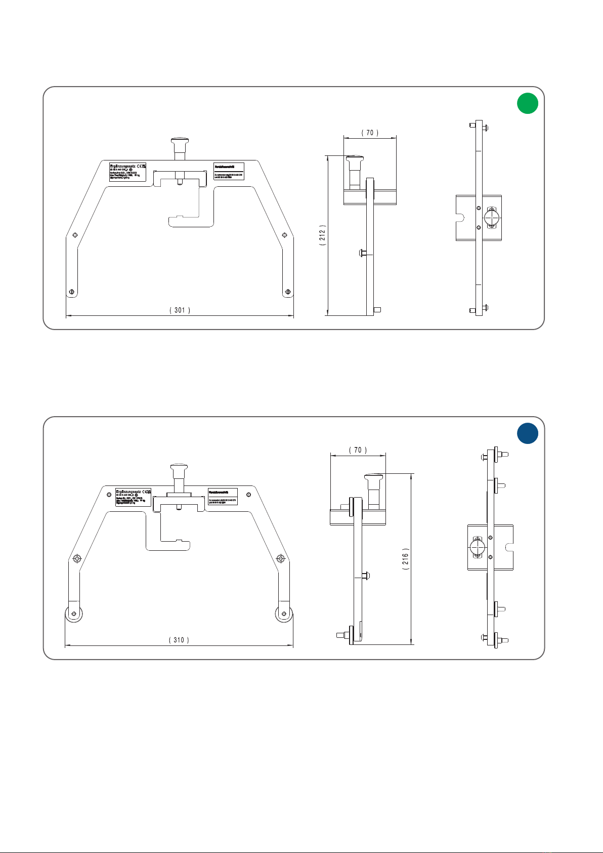
2.1 Technical Specifications
Holding modul SE10-01
Item number 83 30 5 A45 C68_A
Weight 0,53 kg
Max. Nominal load 55 kg
Dimensions (W x H x D) in mm 301 x 212 x 70
Coefficient for the static test 2 times (for deformation), 3 times (for fracture)
Temperature -20 °C to +60 °C / -4 °F to 140 °F
Holding modul SE10-02
Item number 83 30 5 A45 C68_B
Weight 0,61 kg
Max. Nominal load 55 kg
Dimensions (W x H x D) in mm 310 x 216 x 70
Coefficient for the static test 2 times (for deformation), 3 times (for fracture)
Temperature -20 °C to +60 °C / -4 °F to 140 °F
10
I
K
2.2 Technical data
Width: 310 mm
Height: 216 mm
Depth: 70 mm
Width: 301 mm
Height: 212 mm
Depth: 70 mm
front left top
front left top
83 30 5 A45 C68_B Supplementary set holding module SE10-02
83 30 5 A45 C68_A Supplementary set holding module SE10-01

11
D
D
FF
GG
AA
B
C
H
H
B
C
E
I
K
2.3 Device components
AScrew short M6 25 mm
BScrew long M6 30 mm
C
Parking position A/B
DLocking bolt
EShaft screw
FHolder
GSlider
HPan head screw M6 x 16
I Holding module SE10-01
K Holding module SE10-02
12
Intended use
Improper use
The tool kit 83 30 5 A45 C68 is used exclusively to carry a load of max. 55 kg as specified
by BMW AG.
The holders may only be used in conjunction with 83 30 5 A45 C70 retrofitted with
83 30 5 A2D EB9.
The load capacity of 55 kg stated on the 83 30 5 A45 C68 tool kit is the maximum nominal
load that may be lifted with this tool. The tools must not be used for any other purpose.
Lifting or lowering the tool is prohibited as long as persons are in the danger zone
of the load.
It is forbidden to stand under the load during the lifting or lowering process.
The operator must not initiate a lifting or lowering operation until he is satisfied that the
tool is properly secured.
It is forbidden to loosen the bolts of the tool when it is loaded.
When installing the tool, make sure that the operator is not endangered by the tool itself
or by the lifting equipment.
Lifting / lowering the load must be done slowly and carefully.
Consult the manufacturer before using the tool in special atmospheres (high humidity,
salty, corrosive, alkaline).
CAUTION
Risk of damage to property and personal injury
If the tool is defective, take it out of operation immediately.
Use only in conjunction with the accessories approved by the manufacturer and the
OEM (see OEM repair instructions and systems).
Use only in conjunction with a suitable lifting device that has sufficient load-bearing
capacity and stability
Make sure that the load does not swing / oscillate.
Only modules approved by BMW AG may be used.
3.1 Intended use

13
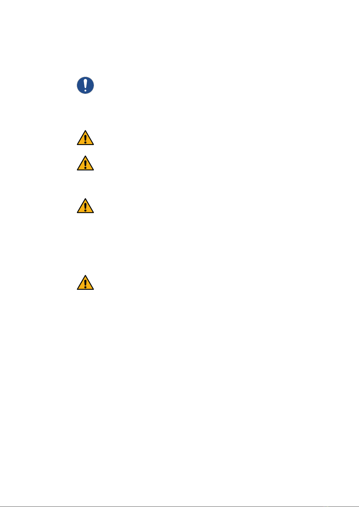
3.3.13.3.1
I
K
L
M
Risk of injury
The tool must be positioned so that there is no risk
of crushing.
Load capacity
Make sure that the rated load of 55 kg is not exceeded
when using the tool.
Stable positioning
The lifting device may only be used on level, fixed and
horizontal ground.
3.2 Working with the tool - basic principles
3.3 Mounting and commissioning
Warranty
The manufacturer accepts no liability for damage
caused by improper repair.
Incorrect operation of the device which results in
damage to the device excludes warranty.
Only use the screws supplied.
Only use the specified adjustment positions.
The lifting device may only be moved in the low-
est position.
Observe the lifting device and load during all
movements.
Follow the BMW repair instructions.
Remove and lift the module according to BMW
instructions.
Take into account the approval of the lifting device.
Take into account the permissible lifting weight
of the lifting device.
I Holding module SE10-01
KHolding module SE10-02
LTraverse
(83 30 5 A45 C70 &
83 30 5 A2D EB9)
MLashing strap
(Accessory 83 30 5 A45 C70)
14
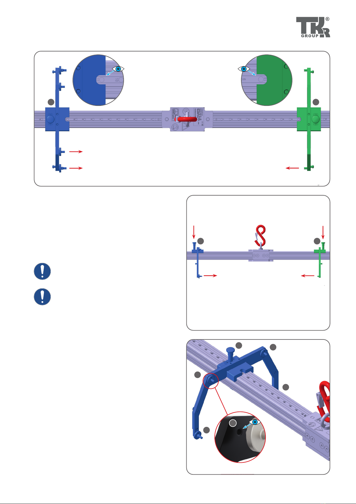
3.3.2 3.3.3
3.3.4
3.3.5
D
D
D
L
N
L
3.3.2 - 3.3.3
For the assembly of the supplementary set 83 30 5 A45 C68,
place the holders SE10-01 and SE10-02 on the traverse [L] via
the groove [N] on the underside of the profile, as required. Make
sure that both the screw „B“ and the screw „A“ for the intended
module are used for the SE10-02 holder ( 3.4, 3.5).
3.3.4 - 3.3.5
To move the holder on the profile, the locking bolt [D] must be
pulled up. Depending on the module, the holder must be moved
to the respective marking (1-35). Read the marking through the
recess in the slide (3.3.5).

15
3.4.1
3.4.2
3.4.33.4.3
D
D
D
A
A
B
B
C
IK
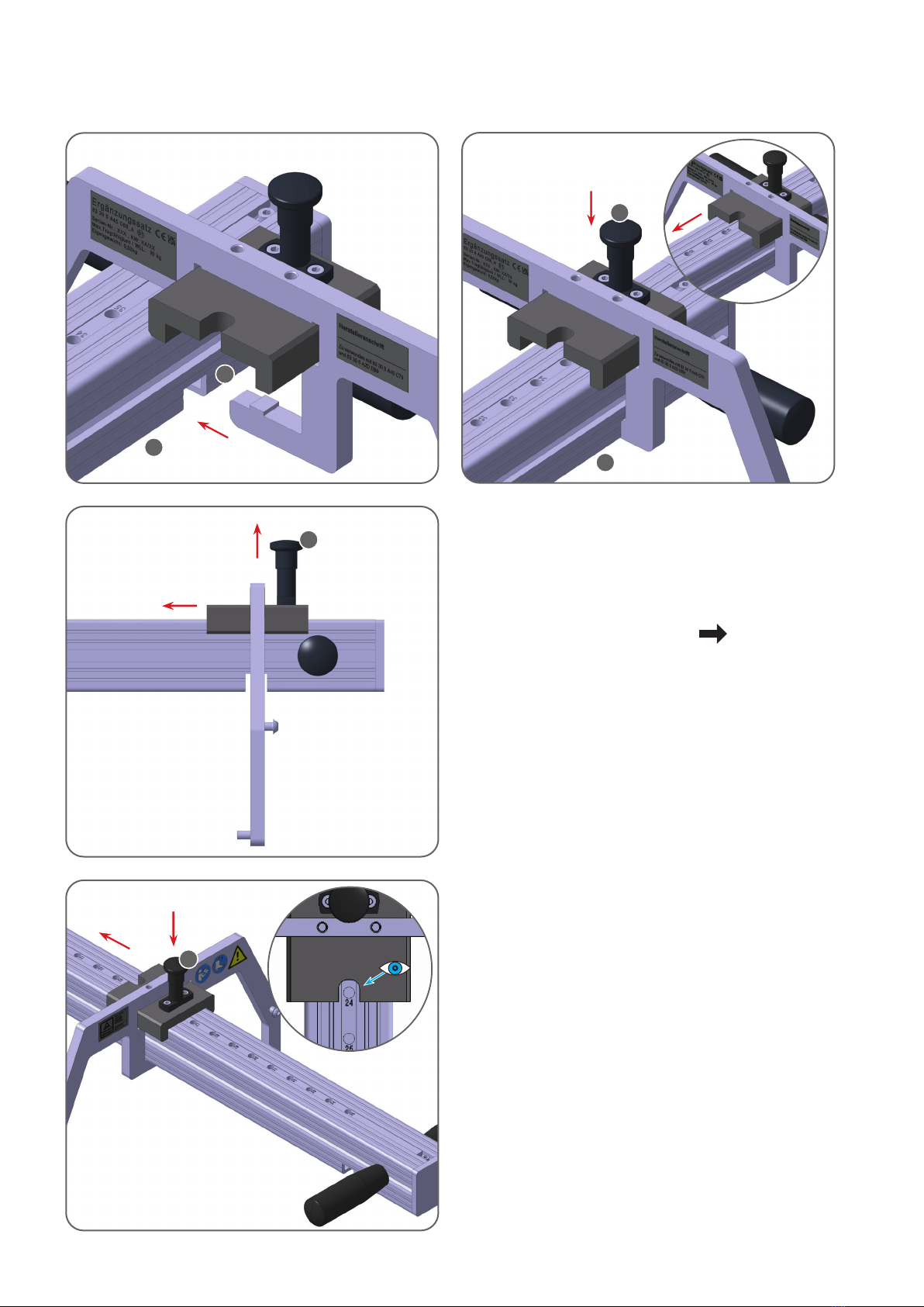
3.4.1 - 3.4.3 Setting position 7 and 8
For the correct use of the tool 83 30 5 A45 C68, slide the crane
operation holders to positions 8 [I] and 7 [K] and lock them
with the locking bolt [D]. Use the screws „A“ [A] on the SE10-02
[I] holder. Meanwhile, the screws „B“ [B] come into the parking
position [C] provided for this purpose. Make sure that the holders
are arranged symmetrically to avoid tilting or skewing of the tool.
Make sure that the holding pins always point in-
wards (3.4.1), otherwise the tool cannot be used.
Make sure that the holders are installed as shown
in the pictures.
3.4 Application - single module
16
3.4.43.4.4
3.4.53.4.5
3.4.6
D
D
E
E
H
I
M
H
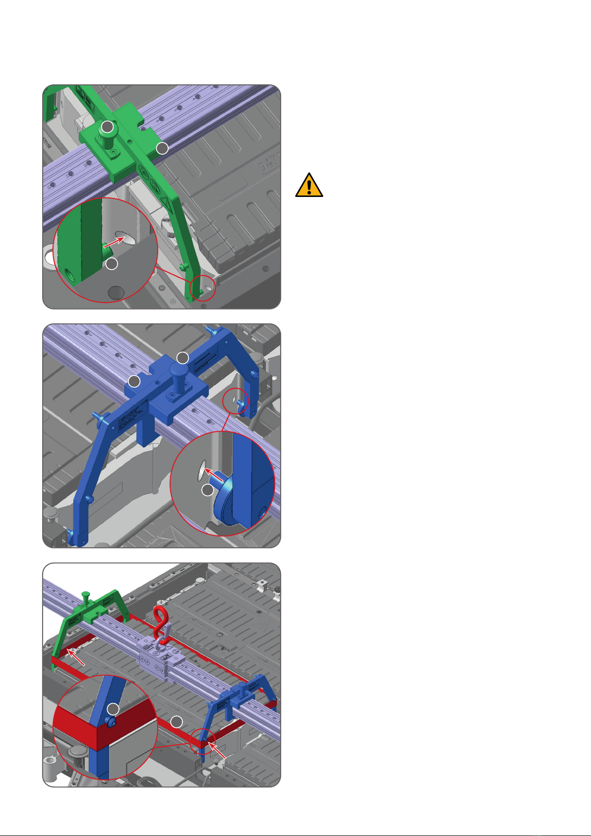
3.4.4 - 3.4.6
Insert the shaft screws [E] of the holders 83 30 5 A45 C68 into
the holes (3.4.4-3.4.5) of the single module. Fix with the locking
bolt [D] at position 7and 8. Connect the holders for securing
with the lashing strap [M] from the tool kit 83 30 5 A45 C70.
The single module may only be lifted when the
shaft screw [E] are fully seated in all mounting
holes and the lashing strap [M] is attached below
the pan head screw [H] (3.4.6).
17
3.5.1
3.5.2
IK
3.5.33.5.3
A
A
B
B
C
D
D D
3.5 Application - double module
3.5.1 - 3.5.3 Setting position 10 and 11
For correct use of the tool 83 30 5 A45 C68, slide the holders for
crane operation to positions 11 [I] and 10 [K] and lock them with
the locking bolt [D]. Use the screws„B“ [B] on the holder SE10-02
[K]. Meanwhile, the screws„A“ [A] come into the parking position
[C] provided for this purpose. Make sure that the holders are ar-
ranged symmetrically to avoid tilting or skewing of the tool.
Make sure that the holding pins always point in-
wards (3.5.1), otherwise the tool cannot be used.
Make sure that the holders are installed as shown
in the pictures!

18
3.5.43.5.4
3.5.53.5.5
I
K
3.5.63.5.6
M
D
D
E
E
H
3.5.4 - 3.5.6
Insert the shaft screws [E] of the holder 83 30 5 A45 C68 into the
holes (3.5.4-3.5.5) of the double module. Fix with the locking
bolt [D] at position 10 and 11. Connect the holders for securing
with the lashing strap [M] from the tool kit 83 30 5 A45 C70.
The double module may only be lifted when the
shaft screws [E] are fully seated in all mounting
holes and the lashing strap [M] is attached below
the pan head screw [H] (3.5.6).

19
3.6 Completing an operation and tool storage
Always examine the tool for possible damage be-
fore and after use.
Dismantle the tool from the crossbar.
Store tool lying down.
Always store the tool in a dry and safe place. Avoid
contamination.
Clean the tool before storing it.
Important!
Always store the lashing strap together with the
traverse in the designated place.

20
4.1 Troubleshooting
Fault Possible cause Remedy Chapter
Holder does not t
Wrong module Check module labelling 2.3
Wrong holder Only use holders that have been sent along 1.4
Holders points do not t
Wrong holder points Check the holder points 3.1
Incorrect holders Observe the labelling on the type plate 1.3
Module has play
Forgotten lashing strap Use the lashing strap of the tool kit
83 30 5 A45 C70 3.4, 3.5
Lashing strap fastened in the
wrong place
Attach the lashing strap underneath the pan
head screw. 3.4, 3.5
The holder does not sit properly
on the storage unit Wrong screw used Use correct screw 3.4, 3.5
Checks may only be carried out by qualified per-
sonnel. The tool must be inspected at least once a
year. If you are using the tool frequently, carry out
the inspection at shorter intervals. Essentially, the in-
spections are visual and functional ones, required to
evaluate the condition of parts in terms of damage,
wear, corrosion or other changes and to determine
the completeness and effectiveness of the safety fa-
cilities.
Repairs may only be carried out by the manufacturer
or by persons authorized by the manufacturer.
4.2 Regular checking and maintenance
Repair surface damage to prevent corrosion. Clean
the device every six months, when heavily contam-
inated or as necessary.
The checks must be arranged by the operator.
The nameplate must always be perfectly legible.
Otherwise the operating permit will be invalidated.
All screw connections must be checked regularly for
tightness.
Table of contents
Other TKR Group Tools manuals


Popular Tools manuals by other brands


Desoutter
Desoutter SB010-AB1600-S4Q manual

Emerson
Emerson Fisher P520L instruction manual

Gage Bilt
Gage Bilt GB745/206-500 Original instructions

RIDGID
RIDGID JobMax E Series Operator's manual

Parkside
Parkside PUS 4 A1 Operating instructions and safety instructions

Cessna
Cessna 172S Skyhawk Pilot operating handbook


