TL Elektronic TL-3724 User manual

TL-3724 USER`S MANUAL
http://www.manuallib.com/file/2615807
From ManualLib.com
ManualLib.com collects and classifies the global product
instrunction manuals to help users access anytime and
anywhere, helping users make better use of products.
Home: http://www.manuallib.com/ Chinese: http://www.shuomingshuku.com/
This Manual: http://www.manuallib.com/file/2615807
ü
TL-3724
USER`S MANUAL
TL elektronic
Airport, Building 125, Hradec Kralove
503 41, Czech Republic
TL
© Copyright 2003, TL elektronic Non TSO approved
This Manual: http://www.manuallib.com/file/2615807

© Copyright 2003-2006
TL elektronic
All Rights Reserved
Except as expressly provided below, no part of this manual may be downloaded, transmitted, copied,
reproduced, disseminated or stored in any storage medium, for any purpose without the express prior
written consent of the TL elektronic company.Address your questions about the technical information
to TL elektronic. Other information about sale, distribution should be directed to our exclusive
distributors (see World Distributor list on our website).
Producer‘s address:
TL elektronic Inc.
Airport, Building 125,
503 41 Hradec Kralove, Czech Republic
WebsiteAddress: www.tl-elektronic.com
to receive the latest information about the software upgrade.
Send your ideas to innovation@tl-elektronic.com.
We will evaluate your suggestion and provide an update.
Record of revision
Revision Revision Description ECO# Insertion By
date date
A 1/5/03 Initial Release ---
B 1/7/04 Language and design update 0001
C 1/7/05 Inst. / Sens. accuracy added 0002
Window is registered trademark of Microsoft Corporation.
All trademarks and registered trademarks are acknowledged.
SchecK® is registered trademark of TL elektronic.
iFamily® is registered trademark of TL elektronic.
sModern® is registered trademark of TL elektronic.
All information in this User‘s manual is subject to change without prior notice.
Page i TL-3724 USER`S MANUAL
Rev. B P/N 09-3724-2003
This Manual: http://www.manuallib.com/file/2615807

Page ii TL-3724 USER`S MANUAL
Rev. B P/N 09-3724-2003
TABLE OF CONTENTS
1. GENERAL DESCRIPTION
1.1. Introduction........................................................................................... 1-1
1.2. Instrument Description........................................................................... 1-1
1.3. Technical Specifications.............................................................................. 1-2
1.4. Limited Warranty........................................................................................ 1-3
2. INSTALLATION
2.1. Introduction............................................................................................... 2-1
2.2. Rack Consideration.................................................................................... 2-1
2.3. Installation of Accessories.......................................................................... 2-1
2.4. Mounting Rack Dimensions........................................................................ 2-2
3. SYSTEM INTERCONNECT
3.1. Pin Function List........................................................................................ 3-1
3.2. TL-3724 Interconnects.............................................................................. 3-2
3.3. TL-3724 Connector Location.................................................................... 3-3
4. NAV-MENU DESCRIPTION
4.1. How to Control Instrument via NAV-MENU............................................. 4-1
5. INSTRUMENT SETUP
5.1. First Instrument Turn-on............................................................................. 4-1
5.2. Main Set-up Functions‘ Description........................................................... 5-1
6. OPERATION MANUAL
6.1. After-installation Check............................................................................. 6-1
6.2. Engine Name............................................................................................. 6-2
6.3. Long-term Memory of Maximum Measured Values.................................... 6-3
6.4. „READY“ to Take-off............................................................................... 6-3
6.5. „OVER“ Limit Message............................................................................. 6-3
6.6. „SERVICE MESSAGE“............................................................................ 6-3
6.7. Deleting „SERVICE MESSAGE“.............................................................. 6-4
6.8. „LOW POWER“ Message........................................................................ 6-4
7. SchecK® DESCRIPTION
7.1. Method of SchecK® for Storing into Memory............................................ 7-1
8. OPERATION MANUAL
8.1. Instrument Configuration............................................................................ 8-1
8.2. Defined Limit Values.................................................................................. 8-1
8.3. Other Configuration................................................................................... 8-1
This Manual: http://www.manuallib.com/file/2615807

Page 1-1 TL-3724 USER`S MANUAL
Rev. B P/N 09-3724-2003
1. GENERAL DESCRIPTION
1.1. INTRODUCTION
This manual describes the physical, mechanical and electrical features and functions of the TL-3724
Combined Engine Instrument.
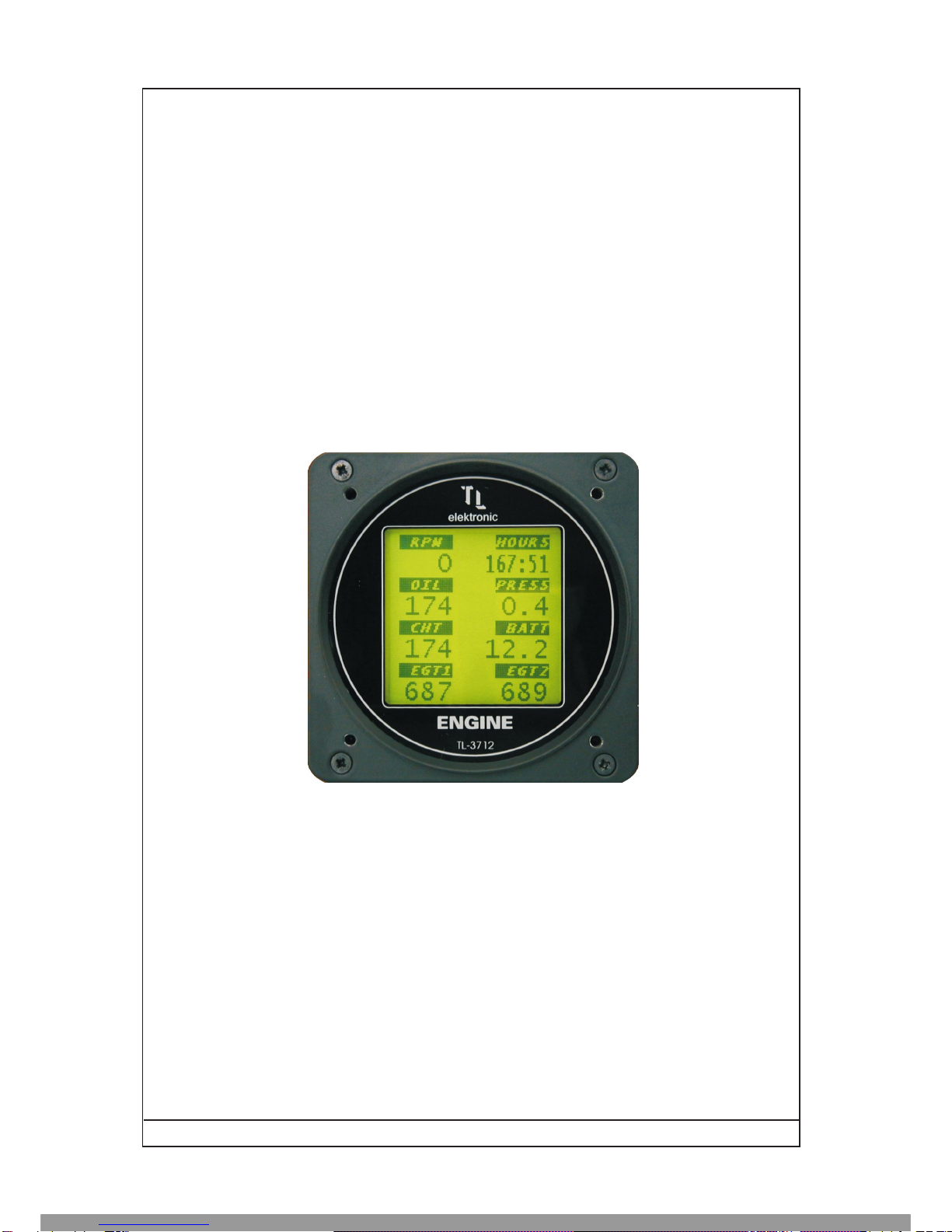
1.2. EQUIPMENT DESCRIPTION
The TL-3724 is a complete engine monitor for measuring all quantities of an engine.
The TL-3724 facilitates seeking the cause of an engine default or damage, with use of the SchecK®
method for storing the measured values into the memory.
The TL-3724 checks all measured values at two levels - for a warning and an alarm limit signalization.
When the alarm warning has been activated, the instrument will display a Service message after the next
turn-on to inform the user on the exceeded some value.
The instrument incorporates a 2,000-line long-term memory and SchecK memory (see page 5-1) for
storing the measured values at 0.1 to 60 second sample rate.
The TL-3724 incorporates a Memory / Info button for displaying the maximum measured values and
other information.
It is possible to download the measured values from the instrument via the serial cable RS-232c into your
PC.
The placement of the values on the display, as well as setting the quantity you want to
show, can be changed at any time with use of the Windows program delivered with the
instrument.
The producer of the engine instrument and its distributor reserve the right not to announce
the correct code as this code helps to decide whether the guarantee can be applied.
1.3. TECHNICAL SPECIFICATIONS
The producer guarantees all stated technical parameters only when the instrument is installed by an
authorized service or an aircraft works.
1.3.1 Physical characteristics
Width 85mm (3.346 inches)
Height 85mm (3.346 inches)
Depth 104mm (4.094 inches) including connectors with cover
Panel hole 80mm (3.149 inches) diameter
TL-3724 Weight 0.4 kg (0.88 lbs)
TL-3724 Harness 0.05 kg (0.11 lbs)
This Manual: http://www.manuallib.com/file/2615807
Page 1-2 TL-3724 USER`S MANUAL
Rev. C P/N 09-3724-2003
1.3.2 General Specifications
Operating Temperature Range -20°C to +70°C
Humidity 95% non-condensing
Altitude Range 4600 metres max.
Power Range 10.0 to 32.0 Volts
Max. Signalization 30 Volts, 1 Ampere
Power Consumption 0.25 Ampere @ 14 VDC
Backlight Consumption ext. input 0.25 Ampere @ 14 VDC
Measuring accuracy ±1% @ 25°C
Vibration 5 to 500 Hz
Sample Rate (LCD Refresh) 1 second
1.3.3 Long-term Memory and Communication
Storing Rate 0.1 to 60 seconds user selectable
Memory Capacity Scheck® method
Stored Values 8 parameters from LCD
Data Saved Endurance 30 years
Rolling Memory life-time 50 000 hours @ 1 second storing rate
Communication RS-232c
Communication Speed 38400 bps
1.3.4 Sensor Parameters / Measured Range / Accuracy / Resolution
3724-01 - EGT Temperature thermocouple K -35 °C to +1200 °C / ±5°C / 1°C
3724-16 - EGT probe (Rotax) thermocouple K -35 °C to +1150 °C / ±5°C / 1°C
3724-02 - CHT Temperature thermocouple J -35 °C to +900 °C / ±2°C / 1°C
3724-04 - W/O sens. (Rotax) VDO black/yelow isolator 0 to +160 °C / ±3°C / 1°C
3724-14 - W/O sens. (Jabiru) VDO gray isolator 0 to +160 °C / ±3°C / 1°C
3724-03 - Oil (Rotax 2-stroke) 399S thermistor 0 to 110 °C / ±4°C / 1°C
3724-15 - W/O probe (Rotax) PT-100 -20 to +240 °C / ±2°C / 1°C
3724-05 - Pressure (Rotax) VDO 29/12 0 to 10 bars /±0.2 Bars / 0.1 Bars
3724-13 - Pressure sens. (Jabiru) ELT 0 to 5 bars / ±0.2 Bars / 0.1 Bars
3724-06 - Pressure sensor Honeywell 0 to 10 bars /±0.1 Bars / 0.1 Bars
Voltage Internal 10.0 to 16.0 V / ± 0.2 Volts / 0.1 Volts
Low RPM voltage ±6 to ±50 VAC / 500 to 9999 rpm / ±10 / 10 rpm
High RPM voltage ±25 to ±80 VAC / 500 to 9999 rpm / ±10 /10 rpm
Positive RPM only +6 to +60 VDC / 500 to 9999 rpm / ±10 / 10 rpm
(VAC can be applied)
Engine Hours 0 to 9999.5 hours / ±2 seconds @ 1 hour
This Manual: http://www.manuallib.com/file/2615807

Page 1-3 TL-3724 USER`S MANUAL
Rev. B P/N 09-3724-2003
This product is not TSO approved as a flight instrument, therefore, the manufacturer
will not be held responsible for any damage caused by its use.
The TL elektronic company is not responsible for any possible damage of an engine
or its destruction caused by default measurement of the instrument.
1.4. LIMITED CONDITIONS
1.5. LIMITED WARRANTY
The TL elektronic company warrants this product to be free from defects in materials and manufacture for
three years from the date of purchase. TL elektronic will, at its sole option, repair or replace any
components that fail in normal use. Such repairs or replacement will be made at no charge to the
customer for parts or labour. The customer is, however, responsible for any transportation costs. This
warranty does not cover failures due to abuse, misuse, accident or unauthorized alteration or repairs.
THE WARRANTIES AND REMEDIES CONTAINED HEREIN ARE EXCLUSIVE AND IN
LIEU OF ALL OTHER WARRANTIES EXPRESS OR IMPLIED OR STATUTORY,
INCLUDING ANY LIABILITYARISING UNDER ANY WARRANTY OF ENCHANT ABILITY
OR FITNESS FOR A PARTICULAR PURPOSE, STATUTORY OR OTHERWISE. THIS
WARRANTY GIVES YOU SPECIFIC LEGAL RIGHTS, WHICH MAY VARY FROM STATE
TO STATE.
IN NO EVENT SHALL TL ELEKTRONIC BE LIABLE FOR ANY INCIDENTAL, SPECIAL,
INDIRECT OR CONSEQUENTIAL DAMAGES, WHETHER RESULTING FROM THE USE,
MISUSE, OR INABILITY TO USE THIS PRODUCT OR FROM DEFECTS IN THE PRODUCT.
SOME STATES DO NOT ALLOW THE EXCLUSION OF INCIDENTAL OR
CONSEQUENTIAL DAMAGES, SO THE ABOVE LIMITATIONS MAY NOTAPPLY TO YOU.
To obtain warranty service, call the TL elektronic Customer Service (+420 49 548 23 92) for a returned
merchandise tracking number. The unit should be securely packaged with the tracking number clearly
marked on the outside of the package and sent freight prepaid and insured to a TL elektronic warranty
service station. A copy of the original sales receipt is required as the proof of purchase for warranty
repairs. TL elektronic retains the exclusive right to repair or replace the unit or software or offer a full
refund of the purchase price at its sole discretion.
SUCH REMEDY SHALL BE YOUR SOLE AND EXCLUSIVE REMEDY FOR ANY BREACH
OF WARRANTY.
1.6. LIMITED OPERATION
This Manual: http://www.manuallib.com/file/2615807

Page 2-1 TL-3724 USER`S MANUAL
Rev. B P/N 09-3724-2003
2. INSTALLATION
2.1 INTRODUCTION
Careful planning and consideration of the suggestions in this section are required to achieve the desired
performance and reliability from the TL-3724.
2.2 RACK CONSIDERATION
Plan a location that gives the pilot complete and comfortable access to the entire keypad and that is plainly
visible from the pilot’s perspective. Check that there is adequate depth for the rack in the instrument panel.
A place away from heating vents or other sources of heat generation is optimal.
2.3 INSTALLATION OFACCESSORIES
Make sure that the sensor connection corresponds with the set configuration of the instrument according to
the Instrument Configuration. In other case, contact an authorized distributor for the correct sensor setting.
Connection of sensors and other parts must be done properly to avoid any damage.
Connect the cables into the connector and use the connector cover.
Secure the incoming leads to prevent their effect on the connector
in the vertical direction.
This Manual: http://www.manuallib.com/file/2615807

Mounting Rack Dimension
Figure 1. Rack Dimension
Engine instrument TL-3724
P/N 09-3724-2003
elektronic
ENGINE
TL-3724
M3.5 (0.137) 4x
+
+
+
+
85 (3.346)
80 (3.149)
31.5 (1.240) 31.5 (1.240)
85 (3.346)
31.5 (1.240)
31.5 (1.240)
Page 2-2
Rev. A
TL
62 (2.440)
2 (.007)
85 (3.346)
80 (3.149)
40 (1.574)
NOTES:
1. Dimension: mm (INCH)
2. Unit weight: 0.4 kg (0.88 lbs)
3. Mounting Rack & Hardware
weight: 0.05 kg (0.11 lbs)
This Manual: http://www.manuallib.com/file/2615807

Pin Pin Name I/O
1 Flow sensor input In
2 Power +12 Volts for fuel flow and oil pressure sensor Out
3 Pressure sensor input In
4 Ground for fuel flow and oil pressure sensor - -
5 Alarm signalization Out
6 Ground for RS-232 communication - -
7 RS-232 IN In
8 RS-232 OUT Out
9 Memory / Info button input In
10 Ground for Memory / Info button - -
11 iFamily® communication ISCL I/O
12 iFamily® communication ISDA I/O
13 Thermocouple No.1 - positive input In
14 Thermocouple No.1 - negative input In
15 RPM High voltage input In
16 RPM Positive voltage input In
17 Thermocouple No.2 - positive input In
18 Thermocouple No.2 - negative input In
19 RPM Low voltage input In
20 Ground for RPM sensor - -
21 Thermocouple No.3 - positive input In
22 Thermocouple No.3 - negative input In
23 Display backlight - source for Jump Out
24 Display backlight - input In
25 Thermocouple No.4 - positive input In
26 Thermocouple No.4 - negative input In
27 Aicraft power In
28 Aircraft ground - -
29 Thermocouple No.5 - positive input In
30 Thermocouple No.5 - negative input In
31 Oil temperature or IAT sensor In
32 Ground for oil temperature or IAT sensor - -
33 Thermocouple No.6 - positive input In
34 Thermocouple No.6 - negative input In
35 Water temperature or OAT sensor In
36 Ground for water temperature or OAT sensor - -
Page 3-1 TL-3724 USER`S MANUAL
Rev. C P/N 09-3724-2003
3.1 PIN FUNCTION LIST
This Manual: http://www.manuallib.com/file/2615807

P3701
(SEE NOTE 2)
(SEE NOTE 3)
MEMORY / INFO
BUTTON
9
10
5
27
31
32
35
36
3
4
28
BUTTON1 - MEMORY1
GROUND FOR BUTTON 1
10-32VDC AIRCRAFT POWER
OIL OR IAT SENSOR
GROUND FOR OIL OR IAT SENSOR
WATER OR OAT SENSOR
GROUND FOR WATER OR OAT SENSOR
PRESSURE SENSOR
GROUND FOR PRESSURE SENSOR
AIRCRAFT GROUND
SIGNALIZATION
THERMOCOUPLE SENSOR (+)
THERMOCOUPLE SENSOR (-)
THERMOCOUPLE SENSOR (+)
THERMOCOUPLE SENSOR (-)
THERMOCOUPLE SENSOR (+)
THERMOCOUPLE SENSOR (-)
THERMOCOUPLE SENSOR (+)
THERMOCOUPLE SENSOR (-)
THERMOCOUPLE SENSOR (+)
THERMOCOUPLE SENSOR (-)
THERMOCOUPLE SENSOR (+)
THERMOCOUPLE SENSOR (-)
POSITIVE PULSE ONLY
HIGH AMPLITUDE
LOW AMPLITUDE
GROUND
DISPLAY BACKLIGHT
DISPLAY BACKLIGHT
RPM SENSOR
EGT / CHT No.1
EGT No.2
EGT No.3
/ CHT
/ CHT
EGT / CHT No.4
EGT / CHT No.5
EGT / CHT No.6
13
14
17
18
21
22
25
26
29
30
33
34
16
15
19
20
23
24
8
7
6
11
12
RS 232 OUT
RS 232 IN
IFAMILY®
GND
IFAMILY® ISCL
ISDA
?
16,15,19
TL-3724
COMBINED INSTRUMENT
Accessories Interconnect
Figure 2. Accessories interconnect
Engine instrument TL-3724
P/N 09-3724-2003
NOTES:
1. Signalization is connected to the aircraft ground
when active.
2. Jumper for the backlight. For the backlight control
install a resistor between the pins 23 and 24.
3. Use the shade cable only and connect it according
to the connection scheme delivered with the sensor.
D-SUB 9 pins (female)
for communication with a PC
ISDA
54 3 21
67 8 9
ISCL
Connect other
TL elektronic instruments
via the iFamily® Bus
1A
1A
FUSE
FUSE
AIRCRAFT POWER
(Note. 1)
Sign.
unit
Page 3-2
Rev. C
This Manual: http://www.manuallib.com/file/2615807

P3701
2
1
4
2
3
4
2
16
20
POWER FOR FLOW SENSOR
OUTPUT FROM FLOW SENSOR
GROUND FOR SENSOR
POWER FOR PRESSURE SENSOR
OUTPUT FROM PRESSURE SENSOR
GROUND FOR SENSOR
POWER FOR RPM SENSOR
OUTPUT FROM RPM SENSOR
GROUND FOR RPM SENSOR
TL-3724
COMBINED INSTRUMENT
Other Accessories Interconnect
Figure 3. Other Accessories interconnect
Engine instrument TL-3724
P/N 09-3724-2003
NOTES:
1. Use the shade cable only and connect it according
to the connection scheme delivered with the sensor.
ACTIVE THREE-WIRE
PRESSURE SENSOR
ACTIVE THREE-WIRE
ROTATION SPEED SENSOR
SUPPLY +12V
OUT
GND
(Note. 1)
FLOW
SENSOR
PULSE
GROUND
SUPPLY +12V
(Note. 1)
OUTPUT
GROUND
SUPPLY +12V
(Note. 1)
Page 3-3
Rev. A
This Manual: http://www.manuallib.com/file/2615807
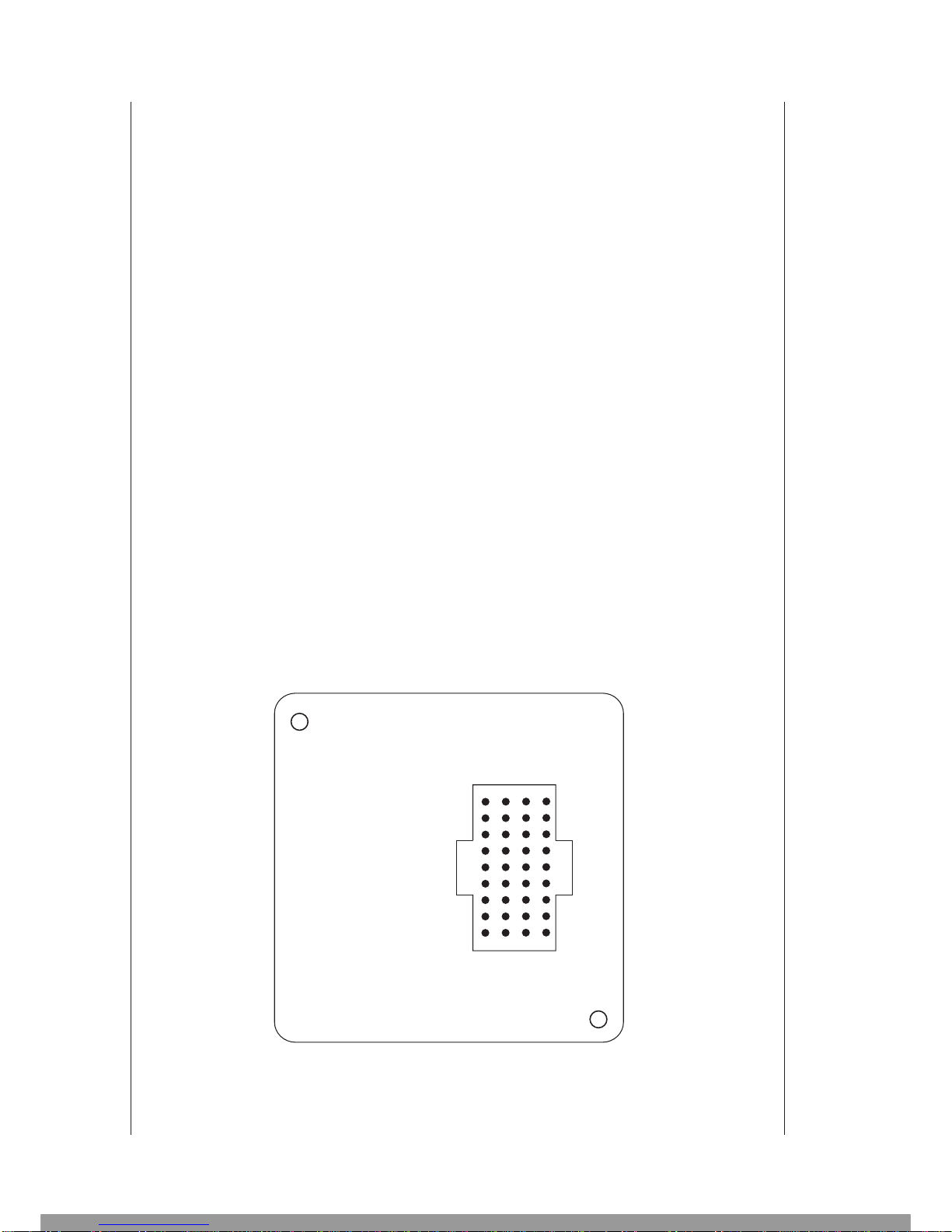
Rear view of connector plate
NOTES:
1. Use delivered connector black cover
for cable protect.
Figure 5. Connectors locate
Engine instrument TL-3724
P/N 09-3724-2003
P3701
1
36
Page 3-4
Rev. A
This Manual: http://www.manuallib.com/file/2615807

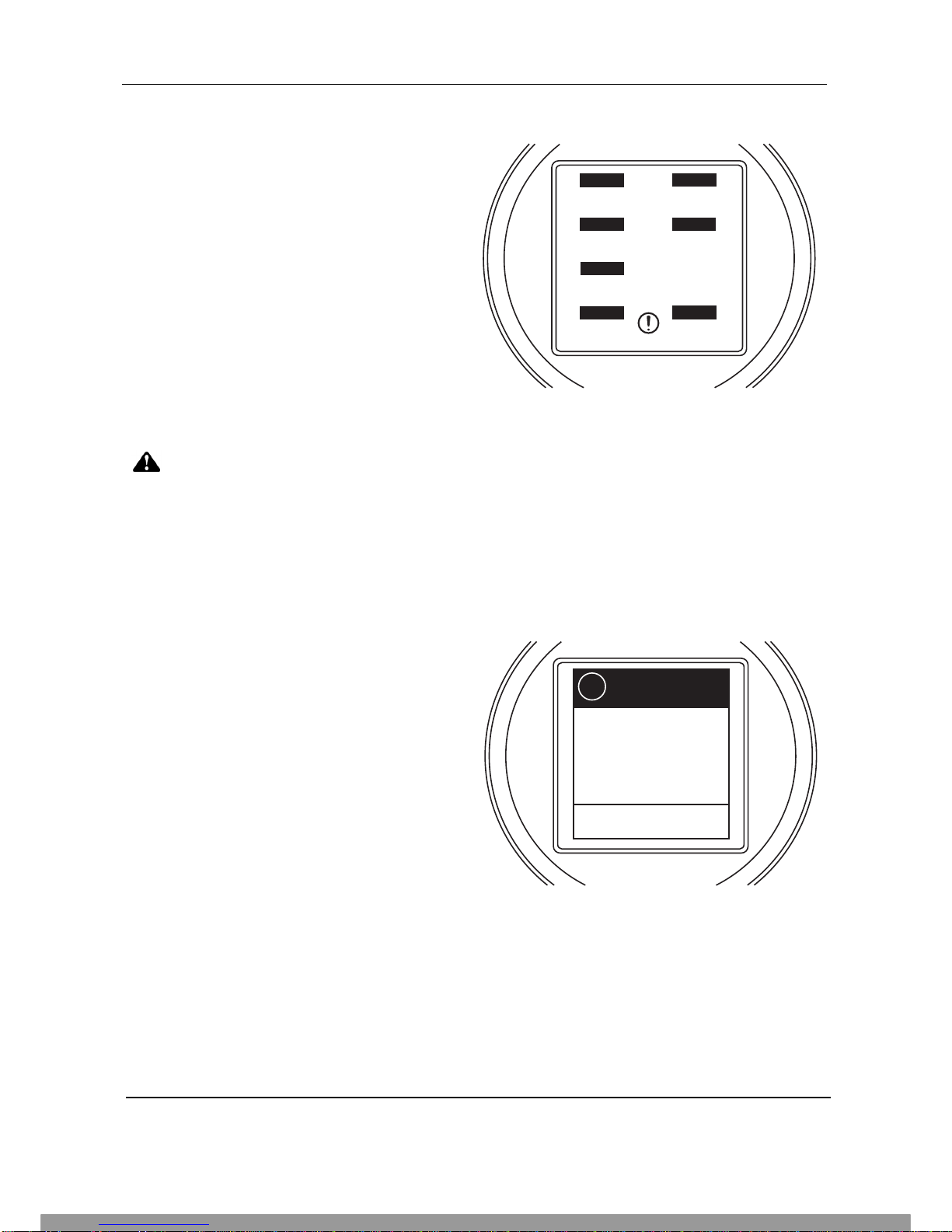
4. NAV-MENU DESCRIPTION
4.1 How to Control Instrument via NAV-MENU
There are black labels on the display.
The function of the left label can differ in each
menu.
The left label is for the Left button.
The left label is affiliated to the User/Memory
button. Before pressing a button, read the
information on the label.
The right label provides information.
This label is not affiliated to any button and provides information only. Usually, you can find an instruction
on this label such as „WAIT“ for waiting for an operation to be completed or „OFF“ for turning the
instrument off.
5. INSTRUMENT SETUP
5.1 First Instrument Turn-on
Before the Combined Instrument starts to
indicate, you must do the basic setting of
quantities, contrast, units, etc.
The set-up can be done only via PC. This set-up
must be completed to continue.
Page 4-1 TL-3724 USER`S MANUAL
Rev.A P/N 09-3724-2003
FIRST SETUP
ENGINE
elektronic
MUST BE COMPLETE
BEFORE FIRST USE
CONNECT YOUR PC
SERVICE
MESSAGE
INFO WAIT
For more information
press info button.
CHECK MEMORY !
ENGINE
elektronic
This Manual: http://www.manuallib.com/file/2615807

5.2 Main Set-up Functions‘ Description
The table of the instrument configuration steps is shown below (Initial - firmware version 5.2).
0 PASSWORD Enter your password.
1 CHANGE LOGO Enter a new logo, which will show after turning
the instrument on.
2 QUANTITIES Select the quantities that will show on the display in
the position given by the drop-down menus‘ order.
3 INPUT Set for the measured quantity EGT or CHT the number
of the input to which the particular sensor is connected.
4 TYPE OF SENSOR Select the sensor type for the particular measured quantity.
5 WARNING LIMIT Set the Warning limit for the particular measured quantity.
6 ALARM LIMIT Set theAlarm limit for the particular measured quantity.
7 S/N Enter the series number of your engine.
8 TYPE OF ENGINE Select the engine type.
9 DISPLAY MESSAGE Enter the name of your engine, which will show after turning
the instrument on.
10 PULSE PER REV. Set the number of pulses corresponding with one engine
rotation.
11 TOTAL TIME Enter the initial engine hours.
12 TEMPERATURE UNIT Select your local unit for temperature.
13 PRESSURE UNIT Select your local unit for pressure.
14 FLOW K-FACTOR Set the K-FACTOR for the fuel flow sensor.
15 FLOW AVERAGE Set the interval of averaging the instant fuel consumption in
seconds (the averaging interval will ensure a more stable
reading).
16 FLOW UNITS Select your local unit for fuel flow.
17 BUTTON CLEAR Select the mode of deleting the „SERVICE MESSAGE“
ENABLE = deleting by pressing the button and turning the
instrument on, DISABLE = deleting is possible via PC only.
18 READY OIL Set the oil temperature at which your engine is hot for the
take-off.
19 READY FOR RPM Set the rotation speed at which the message „COLD
ENGINE“ will be stored into the memory in case of exceeding
this rotation speed while the oil temperature is lower than the
one set in the „READY OIL“.
20 MIN. OIL LIMIT Set the Warning limit for the minimum oil pressure.
21 MIN. OIL ALARM Set the Alarm limit for the minimum oil pressure.
22 MIN ACTIVATE RPM Set the RPM at which counting the time will be started
and the set values will start to be checked.
23 DISPLAY CONTRAST Set the display contrast level.
24 VOICE WARNING Enable or disable voice warning into your headphones.
(Only with use of our Intercom TL-2424 or Voice Module)
All information on this page is subject to change without prior notice. Download the latest
version of the manual from www.tl-elektronic.com and compare with you version of firmware.
Page 5-1 TL-3724 USER`S MANUAL
Rev. B P/N 09-3724-2003
This Manual: http://www.manuallib.com/file/2615807

Page 6-1 TL-3724 USER`S MANUAL
Rev. B P/N 09-3724-2003
6. OPERATION MANUAL
6.1 After-installation Check
After the installation, check the correctness of all
connected inputs and turn the instrument on.
After turning the instrument on, check the
correctness of the measured values.
All set values will show on the display. If the
symbol [---] shows, it means that a sensor might
not be connected or might not work.
If the instrument has not been purchased as a part of the engine, the configuration is
required. Do the configuration with use of the Windows program delivered with the
instrument.
If some of the measured values is out of range (the symbol [---] shows on the display)
or if some of the measured values is incorrect, do not start the engine!
If you started the engine, the signalization of exceeding the limits might be activated,
and the incorrect values would be recorded into the memory.
6.2 Engine Name
Make sure that the name of your engine is shown
correctly on the display. Also check whether the
correct local unit for measuring temperature in °C
or °F has been set.
36
37
37
37
4.0
32
2670
00:10
EGT2
EGT1
CHT1
CHT1
PRESS
OIL
RPM
Hours
ENGINE
elektronic
ENGINE
elektronic
NAME
ENGINE
Ver.1.0
°C
á
The pressure units (bars or psi), as well as the fuel consumption units (litres, UK gallons
or US gallons), can be found out in the Windows configuration program or in the download
of the measured values.
This Manual: http://www.manuallib.com/file/2615807

Page 6-2 TL-3724 USER`S MANUAL
Rev. B P/N 09-3724-2003
6.3 Long-term Memory of Maximum Measured Values
After pressing the Memory / Info button, the
maximum measured values of all displayed
quantities will show.
Do not manipulate, connect or disconnect the sensor while the engine is on,
otherwise extremely high values could be recorded.
6.4 „READY“ to Take-Off
The „READY“ message shows when the engine
has reached the operational temperature after the
start-up. This message will show only if the correct
temperature datum has been set.
ENGINE
elektronic
115
648
98
648
5.2
648
4880
CHT
EGT1
OIL
EGT 2
PRESS
EGT 3
RPM
EGT 4
M
E
M
O
R
Y
648
36
37
37
37
4.0
32
2670
00:10
EGT2
EGT1
CHT1
CHT1
PRESS
OIL
RPM
Hours
R
E
A
D
Y
ENGINE
elektronic
This Manual: http://www.manuallib.com/file/2615807
Page 6-3 TL-3724 USER`S MANUAL
Rev. B P/N 09-3724-2003
6.5 „OVER“ Limit Message
The instrument checks the measured values at two
levels. The first one, Warning signalization informs
the pilot by blinking on exceeding the limit and that
more attention should be paid to the measured
values (the yellow field). If the measured value
exceeds the Alarm limit (the red field), blinking will
continue and the „OVER“ message will show.
After the next turn-on of the instrument,
the „SERVICE“ message will show.
The limit value check is activated immediately after the set rotation value for
the activation is reached. Only the minimum oil pressure check is activated after
5 seconds to allow the oil circuit to get pressurized.
6.6 „SERVICE MESSAGE“
If the set limit values have been exceeded, the
„SERVICE MESSAGE“ shows after turning the
instrument on.This information will disappear after
15 seconds and then the instrument get back to the
normal measuring mode.
By pressing the „INFO“ button, the pilot has to find
out which measured item has been exceeded and
eliminate the possible defect.
36
37
37
37
4.0
32
2670
00:10
EGT2
EGT1
CHT1
CHT1
PRESS
OIL
RPM
Hours
O
V
E
R
ENGINE
elektronic
Hours: 11:59
EGT1
ColdOil
ENGINE LIMITS
STATUS TABLE
i
ENGINE
elektronic
This Manual: http://www.manuallib.com/file/2615807
Page 6-4 TL-3724 USER`S MANUAL
Rev. B P/N 09-3724-2003
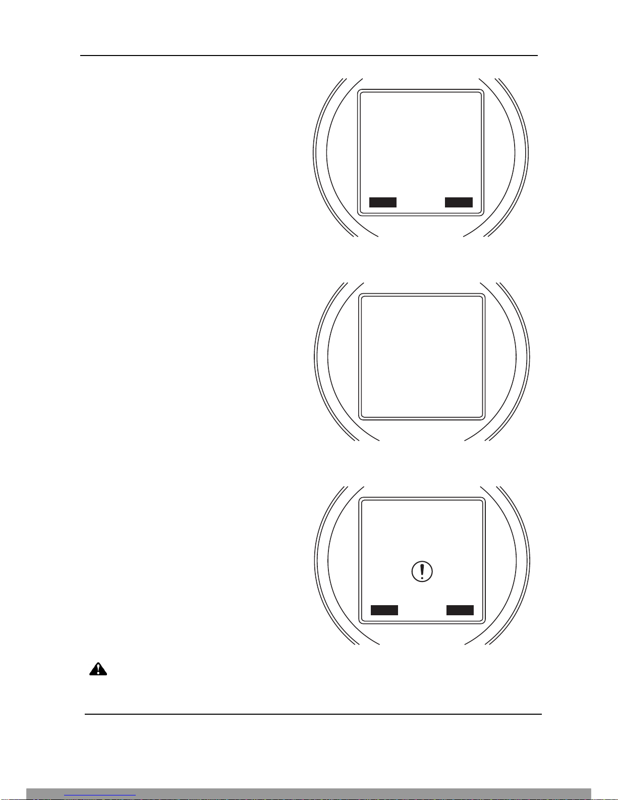
6.7 Deleting „SERVICE MESSAGE“
When deleting the „SERVICE MESSAGE“ has
been enabled in the instrument via the PC control
software, the „SERVICE MESSAGE“ can easily
be deleted by pressing the „INFO“ button and
turning the instrument on at the same time.
After that the „SERVICE DELETED“ message
shows on the display.
6.8 „LOW POWER“ Message
This message will show always when voltage drops
under the operational limit. This may happen during
the engine start up etc. In this case, wait till the
instrument gets back to the normal measuring
mode.
6.9 „SYSTEM ERROR“ Message
If the automatic internal circuit check found out an
error in the instrument or a data integrity defect,
the „SYSTEM ERROR“ message will show on the
display.
Do not try to repair the instrument yourself. Contact a distributor or the producer
with the 2-digit number specifying the error.
SERVICE
DELETED
INFO WAIT
3
ENGINE
elektronic
LOW
POWER
Please Wait
6
ENGINE
elektronic
SYSTEM
ERROR
Code: 00
INFO OFF
ENGINE
elektronic
This Manual: http://www.manuallib.com/file/2615807
Page 7-1 TL-3724 USER`S MANUAL
Rev. B P/N 09-3724-2003
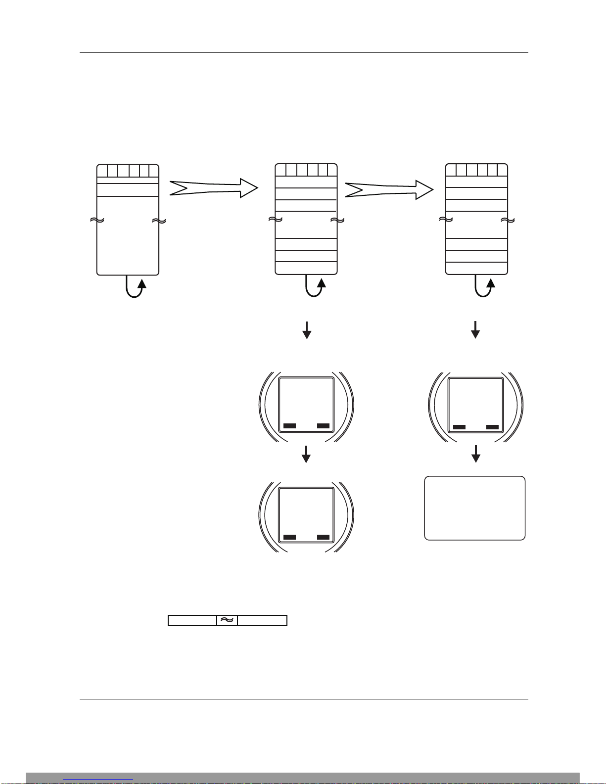
7.1 SchecK memory description
The TL-3724 includes a 2,000 lines long-term memory and SchecK memory for storing measured values
in the 0.1 to 60 second sample rate. You can download the measured data via standard PC serial cable
RS-232 into Laptop or Personal Computer.
Cases 1 to 20 include the record of limit-exceeding values and engine hours, date and time referring
to the moment of limit exceeding. Each case includes 60 lines.
In this version it is possible to read last 20 exceeded records at total operational time.
CONTACT
SERVICE
Call Service
INFO WAIT
)
ENGINE
elektronic
Begin Begin
Transfer a case Transfer a line
Each case (1 to 20) includes
60 lines memory space
with 0.1 to 60 seconds samples
rate of measured values
Each line (1 to 60) includes
all highest measured values
of SchecK
©
case
Rolling memory included
End End
Rolling memory - last 10,000 lines
with 0.1 to 60 second sample rate
Rolling SchecK memory -
last 20 cases
©
When any case is filled,
this message will show
after turning the instrument on.
When all lines are filled,
this message will show
after turning the instrument on
The user can delete
this message.
Rolling lines -
last 60 lines
Measured
values
0.1 to 60
seconds
samples rate
Case 1 Line 1
Case 2 Line 2
Exceeded place
1
Case 3 Line 3
Case 12 Line 58
Case 13 Line 59
Case 14 Line 60
....
This message can be deleted
only by using a special
program, which is possed
only by authorized engine
dealers and when data are
downloaded into a PC
23XXX 123XXX 123XXX
....
30 lines before
limit exceeding
Limit exceeding values
(centered in the middle position)
30 lines after
limit exceeding
SERVICE
DELETED
INFO WAIT
3
ENGINE
elektronic
SERVICE
MESSAGE
INFO WAIT
For more information
press info button.
CHECK MEMORY !
ENGINE
elektronic
This Manual: http://www.manuallib.com/file/2615807
Table of contents
Popular Analytical Instrument manuals by other brands

Dobiy
Dobiy DM6-80m user manual

Extech Instruments
Extech Instruments CO210 user manual

Extech Instruments
Extech Instruments HDV7C-A2-45-15 user manual

VOLTCRAFT
VOLTCRAFT BS-500 operating instructions

VOLTCRAFT
VOLTCRAFT IC-100HD operating instructions

Leuze electronic
Leuze electronic ODS 10 operating instructions


