Tlian T6 User manual

For professional use only
T4 PV CONNECTOR
INSTALLATION
MANUAL
A Canadian Solar subsidiary
T6 PV CONNECTOR
INSTALLATION MANUAL

2|
1. T6 CONNECTOR PARTS
2. T6 PRODUCT SPECIFICATIONS
3. T6 INSTALLATION PARAMETERS
4. SAFETY PRECAUTIONS
5. T6 FIELD TOOLKIT
6. CONNECTOR & WIRE ASSEMBLY STEPS
7. THE CORRECT CONNECTION
8. DISCONNECTING THE CONNECTORS
|3
|3
|4
|4
|5
|6
|8
|8
AMENDED EDITIONS AND DATES |8
UL-Rev IM-TC-UL/1.1 Copyright © Feb.2023. Tlian Co., Ltd.
LIST OF FORBIDDEN CHEMICAL SUBSTANCES |9
|3
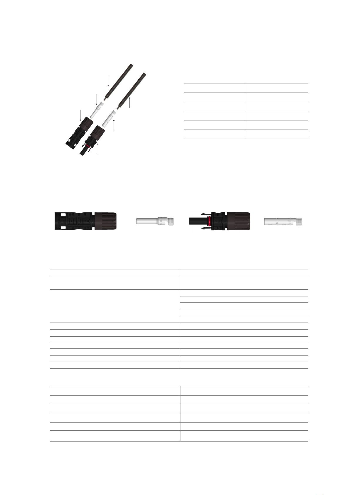
1. T6 CONNECTOR PARTS
③
①
①
④
⑤
②
Connector Specication T6
Rated Voltage IEC 1500 VDC / UL 1500 VDC
IEC 1000 VDC / UL 1500 VDC
Rated Current
41A (4 mm²) / 40A (12 AWG)
48A (4 mm²) / 40A (12 AWG)
50A (6 mm²) / 55A (10 AWG)
54A (6 mm²) / 55A (10 AWG)
70A 10 mm² / 8 AWG
Contact Resistance ≤ 0.25 mΩ
Pollution Degree ClassⅡ
Protection Class ClassⅡ
Protection Degree IP68
Fire Resistance UL 94-V0
Temperature Range - 40 °C ~+ 90 °C
Rated Impulse Voltage 16 kV
2. T6 CONNECTOR SPECIFICATIONS
Connector Specication T6
Cable Specication 12 AWG /10AWG /8AWG
Connector System Φ 4.0 mm
Contact Material Copper, Tin-plated
Type of Termination Crimping/Machined
Locking System (UL) Locking type
Item Part Name
1 PV Cable
2 Male Pin Contact (-)
3 Male Connector (-)
4 Female Socket Contact (+)
5 Female Connector (+)
Male Connector (-) Male Pin Contact (-) Female Socket Contact (+)
Female Connector (+)
ELECTRICAL DATA:
MECHANICAL DATA:
1)Standard:UL6703, UL486A-486B, NFPA7(In Free Air), C22.2 No.182.5
Note:Installation in a free air run with a cable spacing not less than 100% of the largest cable diameter.
4|
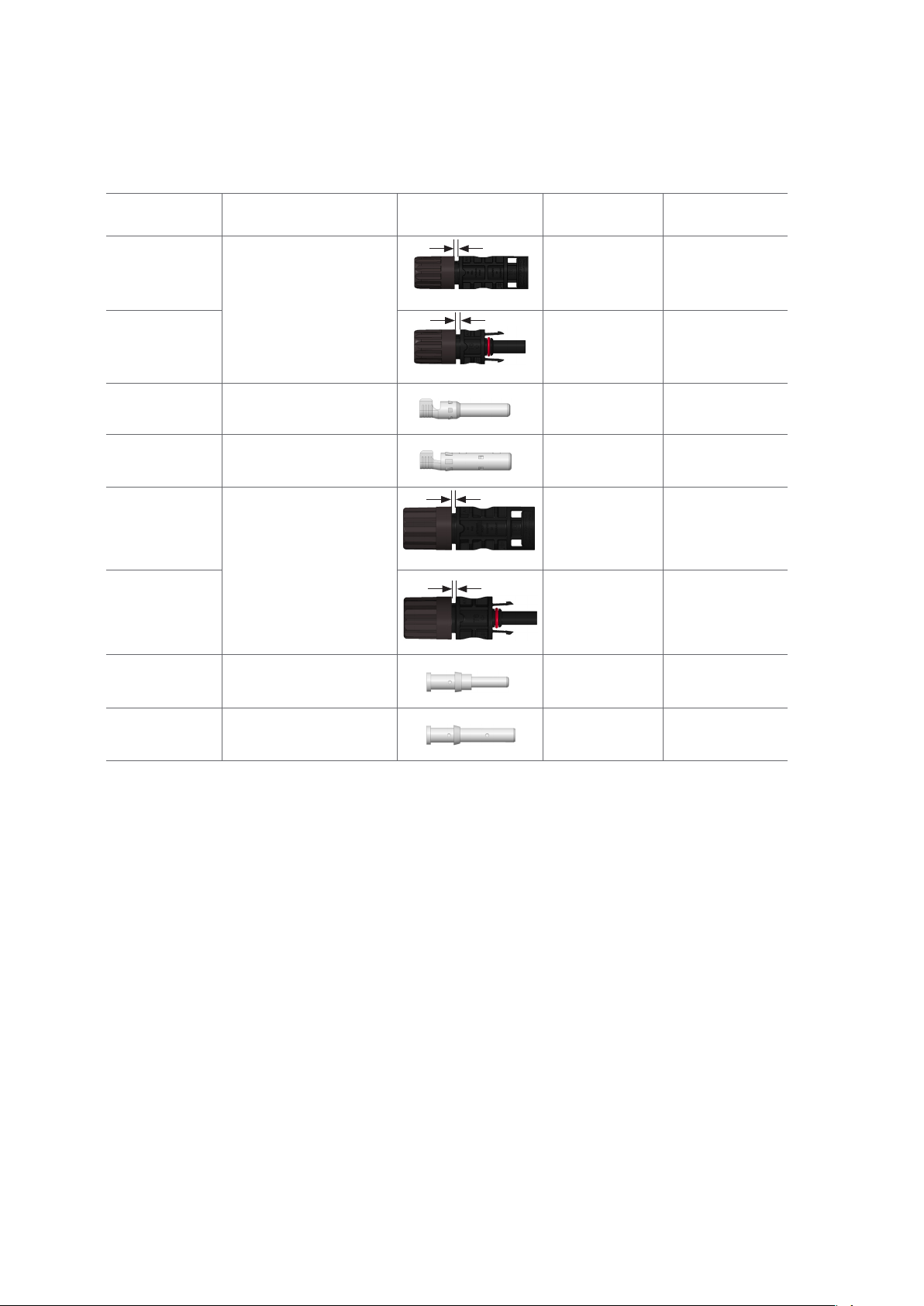
Article Cable Outside Diameter
(OD) Picture Required Torque
to Lock Reference Gap
Male
Connector (-)
4.3mm - 6.9mm
2.5 N•m ~ 3.5 N•m 0.5 ≤ gap ≤ 1.5mm
Female
Connector (+) 2.5 N•m ~ 3.5 N•m 0.5 ≤ gap ≤ 1.5mm
Male
Pin Contact (-) —— —— ——
Female Socket
Contact (+) —— —— ——
Male
Connector (-)
7.2mm - 8.9mm
4N•m ~ 5 N.m 0 < gap ≤ 0.5mm
Female Connector
(+) 4N•m ~ 5 N.m 0 < gap ≤ 0.5mm
Male
Pin Contact (-) —— —— ——
Female Socket
Contact (+) —— —— ——
3. T6 INSTALLATION PARAMETERS
gap
gap
gap
gap
UL-Rev IM-TC-UL/1.1 Copyright © Feb.2023. Tlian Co., Ltd.
4. SAFETY PRECAUTIONS
Products must be assembled and installed by qualied
personnel, ensuring all safety regulations are followed. For
protection against electric shock, please ensure the system
is not energized during installation. Do not disconnect
under load. Ensure that the AC and the DC sides are both
disconnected and the system is not energized before
disconnecting.
Use only the tools and components listed in this installation
manual. Follow the instructions as stated in this manual. Do
not alter or willingly damage the product in anyway.
• Sealing cap must be used on disconnected
connectors to prevent dust ingress.
• Connectors are IP68-rated when mated.
• Do not place connectors directly on roof surface.
• CAUTION1 :
The exposure to or direct contact with chemicals or oils of T6
product may cause corrosion, degradation of performance, or
cracking of the product, thus such exposure or direct contact
should be strictly prohibited during the process of product
manufacturing, transportation, installation and application.
It is the user's responsibility to validate any chemical that may
come into contact with or used in any of the processes men-
tioned above, to ensure that such chemical will not aect the
performance of T6 products.
• CAUTION 2:
Any T6 or T4 products can be intermated with each other.
• CAUTION 3:
Interconnection of dierent connector types/brands with T6 is
not allowed.
• CAUTION 4:
Recycling and all other types of comparable disassembly of the
above mentioned products have to be performed by a qualied
waste management company, in compliance with national and
local waste management regulations.

|5
Wire crimping tool
(12/10/8AWG)
Wire striper
(14/12/10AWG)
T6-10L disconnect tool
Wire striper
(8AWG)
Metal wrench
T6 disconnect
tool
Type Crimping Range
2.5/14 2.5 mm214 AWG
4.0/12 4.0 mm212 AWG
6.0/10 6.0 mm210 AWG
Type Crimping Range
10/8 10 mm28 AWG
Wire crimping tool
Cutting pliers
Wrench
1 set = 2 pieces
Mark Riveting Range
4.0/12 4.0 mm212 AWG
6.0/10 6.0 mm210 AWG
10.0/8 10.0 mm28 AWG
Cutting pliers
5. T6 FIELD TOOLKIT
PARTS INCLUDED IN FIELD TOOLKIT:
Wire stripper tool

6|
6. CONNECTOR & WIRE ASSEMBLY STEPS
STEP 1:
VISUAL INSPECTION OF CONNECTOR
FEMALE CONNECTOR
a. Sealing ring should t cleanly in the slot and
not be warped or distorted.
b. The two plastic clasps should be intact.
c. Female connectors should not be
obstructed by foreign objects or water.
d. Plastic components should not be cracked.
e. No damage should be visible on the cable.
MALE CONNECTOR
a. Male connector should not be obstructed by
foreign objects or water.
b. Plastic components should not be cracked.
c. No damage should be visible on the cable.
STEP 2:
STRIP THE INSULATION OFF THE CABLE
Using the wire stripper tool, remove the insulation from the
cable. For 4/6mm² cable, ensure that the stripping length is
7.5 mm , and for 10mm² cable, the length is 9mm,and that the
wire strands are not damaged during the process of stripping
the insulation.
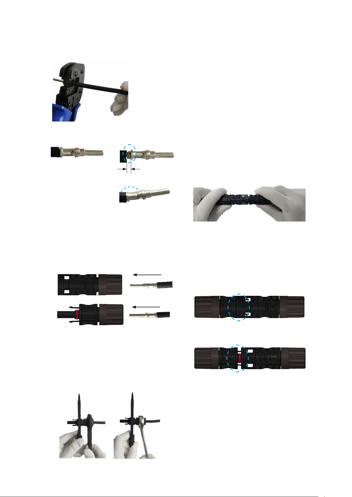
STEP 3:
CRIMP THE CONTACT
4/6mm² Cable
Place the contact around the bare section of the stripped wire.
Crimp the contact using the wire crimping tool. The crimped
contact should withstand pull forces of ≥310 N.
10mm² Cable
Place the contact around the bare section of the stripped wire.
Make sure the wire is visible from the hole .Crimp the contact
using the wire crimping tool. Crimp position is as shown in the
gure.The crimped contact should withstand pull forces of
≥380 N.
Sealing ring
UL-Rev IM-TC-UL/1.1 Copyright © Feb.2023. Tlian Co., Ltd.
7.5 mm
9 mm
Crimp range
4/6mm² Cable
10mm² Cable
|7
STEP 4:
INSERT THE CONTACT
Push the crimped contact back into the connector until
you hear a click. Lightly pull the wire to ensure the
metal components of the connector are engaged.
STEP 5:
TIGHTEN THE CABLE GLAND
First, tighten the gland by hand. Then use the disconnect tools
to tighten the gland to the connector until it clicks, ensuring
that it is locked. When tighteng the male connector, please use
aligner available on the disconnect tool in order to ensure the
pin is not skewed.
STEP 6:
CONNECTING THE CONNECTORS
Check the appearance of the connectors before
connecting them together. The sealing ring should
be in the slot with no warping or distortion. The
plastic clasps should not be damaged or broken. The
connectors should be free of moisture and foreign
objects. Plastic parts should not be cracked. Wire s
hould not be frayed or damaged. When attaching,
insert the connectors into each other until you hear a
“click”. Once attached, gently pull on the connectors to
ensure they are rmly connected and cannot be easily
disconnected by hand.
STEP 7:
VISUAL INSPECTION OF THE CONNECTION
To check the connection, ensure that you cannot see the
sealing ring. The gap between the connectors should be less
than 0.5 mm.
Correct crimping
√
×
Gap ≥ 1 mm
Incorrect crimping
×
Bending
√
×

8|
7. THE CORRECT CONNECTION
Please refer to the detailed instructions of the
minimum bend radius given by the cable
manufacturer
8. DISCONNECTING THE CONNECTORS
The mated connectors can only be disconnected by using the
disconnect tools.
Insert the clasp of the disconnect tool in the slots of the male
connector, and the female connector will automatically get
disconnected .
AMENDED EDITIONS AND DATES
Rev 1.0 was released in Apr 2022
Rev 1.1 was released in Feb 2022
The technical descriptions herein are only for
reference when using these products.
Incorrect bend Correct bend
√
××√
Distance is too close
l ≥ 20 mm l ≥ 20 mm
Incorrect connection Correct connection
×√
Gap ≥ 0.5 mm
Clasp of the dis-
connect tool
Insert into the
slot
Automatically
disconnected
UL-Rev IM-TC-UL/1.1 Copyright © Feb.2023. Tlian Co., Ltd.

|9
Users of T6 products should prevent the exposure of T6 products to any of the following chemical substances
listed below. These chemicals may cause corrosion, degradation of performance, or cracking of product and
might lead to potential safety issues in applications.
Lists of all known chemicals:
Remarks:
For any chemical not listed above that may come into contact with any T6 product,it is the user's responsibility to
validate that such chemical will not aect the performance of T6 products.
Final interpretation is owned by TLIAN
LIST OF FORBIDDEN CHEMICAL SUBSTANCES
Class Chemical Name
Commonly used chemicals
Food release spray, Herbicide, Insecticide, Grease, Lubricate oil, Rust inhibi-
tors, REMA New punch oil, Stamping oil, Engine Oil, Banana Oil, WD-40, Oily
sealing agent, Doduconta B25 Kontaktol, Evabrite S, Virex TB, Suma Lima L3,
Suma Rinse, Detergent, Plasticizer, Spray cleaner8188, CM-31S, REMA cleaner
oil, DX-1, CH1160, Dry lubricating oil, Paint remover, hydraulic oil, Special glue
quick solvent, Gasification rust inhibitor, Dehumidifying anti-rust lubricant,
Cutting oil.
Disinfectants/Cleaners Betadine, Cide, Ammonia, Organic Ammonium Chloride,
Hydrogen peroxide, Bleach, Saline, Detergent.
Cosmetics Hand cream, Sunscreen, Lipstick, Sun screen, Makeup remover.
Oils Die Cut (OELHELD), Machine Oil KV46 (Nippon Oil), Infeld stamping oil.
Edible Corn oil, Cola, Light syrup, Rapeseed oil, Blend oil, Olive oil,
Castor oil, Soybean oil, Coconut oil.
Acid, Alkali, Salt Ammonium hydrogen, Potassium hydroxide, Salt acid, Sulfuric acid, Nitric
acid, Phosphoric acid, Acetic acid, Ammonia, Sodium hydroxide.
Grease Vaseline, Molykote EM-50L (Dow Corning), Molykote PG-641 (Dow Corning).
Mould Release Agent Pelicoat S-6 (Chukyo-Kasei).
Binder Chemlok (LORD).
Alcohols Ethylene glycol, Amyl alcohol, Ethanol, Isopropanol, Isopropyl alcohol (IPA).
Fatty hydrocarbons Heptane,Hexane,Cyclohexane,Liquid paraffin.
Halogenated hydrocarbon Freon,Carbon tetrachloride,Trichloromethane, Virex 256.
Ketone Methyl Ethyl Ketone (MEK),Acetone,Methyl ethyl ketone.
Aromatic Hydrocarbon Toluene,Xylene,Cresol.
Other, Organic solvent
Oleic acid C18H34O2,Nonanal C9H18O,Oleic acidC9H18O2,Ethyl acetate,
Butyl acetate,Tributyl phosphate,Kerosene,Gasoline,
Varnish,Esters,Ethers,Amines,Glacial acetic acid,Print ink,3M.
Adhesion sealant APF125 (Wacker Chemical), 3M adhesive, Avancis adhesive.

10|
TLIAN CO., LTD.
www.csisolar.com
UL-Rev IM-TC-UL/1.1 Copyright © Feb.2023. Tlian Co., Ltd.
Table of contents
Other Tlian Cables And Connectors manuals


Popular Cables And Connectors manuals by other brands


PhDsolutions
PhDsolutions SP-1X2-HD4K Operation manual

Sleep Sense
Sleep Sense Reusable Flow ThermoCan SLS-1477 user manual

STEEL-PLAY
STEEL-PLAY DUAL PLAY & CHARGE CABLE DC5W user manual

Tripp Lite
Tripp Lite P002-002-R Specification sheet

digital world
digital world ARC-SP182 user manual

Tripp Lite
Tripp Lite P781-003 Specification sheet