TLV TrapMan TM5N User manual

172-65592MA-07 (TM5N/TM5N-EX TrapMan Type P) 12 May 2022
Steam Trap Management System
Diagnostic Unit: TM5N/TM5N-EX
(Type P)
Important: In order for the unit to perform highly accurate diagnosis, periodic maintenance
(function check) is necessary. A warning will be displayed on screen when
periodic maintenance is due (when the preassigned date for maintenance is
reached. ex: after 2 years). Please contact TLV at this time to request
maintenance.
If maintenance is not carried out, the unit will be automatically locked.
For details see 1.1 Periodic Required Maintenance.
Copyright © 2022 by TLV CO., LTD.
All rights reserved

172-65592MA-07 (TM5N/TM5N-EX TrapMan Type P) 12 May 2022
1
Contents
Introduction......................................................................................................................................... 3
1. Read Carefully Before Use............................................................................................................. 4
1.1 Periodic Required Maintenance...............................................................................................................4
1.2 For Users of the TM5/TM5-EX and TrapManager (Ver. 3.3.x or earlier)..................................................5
1.3 Safety Considerations..............................................................................................................................6
1.4 Safety Precautions...................................................................................................................................7
1.5 Precautions for Use and Storage...........................................................................................................10
1.6 Steam Traps that cannot be Evaluated..................................................................................................11
2. Functions and Features................................................................................................................ 12
3. Measurement Principles............................................................................................................... 13
3.1 Principles of Steam Leakage Judgement ..............................................................................................13
3.2 Principles of Condensate Backup Judgement .......................................................................................14
3.3 Measurement Position ...........................................................................................................................15
4. Part Names................................................................................................................................... 18
4.1 TM Unit...................................................................................................................................................18
4.2 Probe and Leather Case........................................................................................................................18
4.3 Function Keys ........................................................................................................................................19
5. Preparing for Inspection ............................................................................................................... 20
5.1 Preparing for Inspection.........................................................................................................................20
5.2 Charging the Main Battery for the TM....................................................................................................20
5.3 Connecting the Probe ............................................................................................................................21
5.4 Turning the TM Power ON .....................................................................................................................22
5.5 Turning the TM Power OFF....................................................................................................................22
5.6 Data Communications with the PC ........................................................................................................23
6. Inspection Procedure.................................................................................................................... 24
6.1 Recalling the Control Number................................................................................................................25
6.2 Entering the Control Number .................................................................................................................25
6.3 Using the Probe.....................................................................................................................................27
6.4 Messages Displayed During Measurement ...........................................................................................28
6.5 Entering the Pressure ............................................................................................................................28
6.6 Condensate Load Factor .......................................................................................................................30
6.7 Entering the Temperature Setting..........................................................................................................31
6.8 Judgement.............................................................................................................................................31
7. Judgement.................................................................................................................................... 32
7.1 Recalling Judgements............................................................................................................................32
7.2 Modifying Judgements...........................................................................................................................32
7.3 Re-judgement ........................................................................................................................................33
7.4 Automatic Judgement Items ..................................................................................................................34
7.5 Manual Judgement Items.......................................................................................................................35
8. Using the Function Keys............................................................................................................... 36
8.1 Using the Function Keys........................................................................................................................36
8.2 Tabulating Inspection Results................................................................................................................36
8.3 Searching for Failed Traps.....................................................................................................................37

172-65592MA-07 (TM5N/TM5N-EX TrapMan Type P) 12 May 2022
2
8.4 Changing Settings..................................................................................................................................37
8.5 Automatic Initialization of Settings .........................................................................................................39
8.6 Clearing (Deleting) Inspection Data.......................................................................................................39
9. Information Mode.......................................................................................................................... 40
9.1 Displaying INFOrmation Mode...............................................................................................................40
9.2 INFOrmation Items.................................................................................................................................40
9.3 Entering Text..........................................................................................................................................55
10. For Added Convenience............................................................................................................. 56
10.1 Model Memory Function.......................................................................................................................56
10.2 Model Search Function........................................................................................................................57
10.3 Auto Power OFF Function....................................................................................................................57
11. Using Accessories...................................................................................................................... 58
11.1 Using the Earphone (TM5N (standard type) only)................................................................................58
11.2 Using the Holster .................................................................................................................................58
11.3 Replacing the Main Battery..................................................................................................................59
12. Troubleshooting.......................................................................................................................... 60
12.1 Error Messages....................................................................................................................................60
12.2 Troubleshooting ...................................................................................................................................62
13. Specifications ............................................................................................................................. 65
14. Calibration................................................................................................................................... 66
15. TLV EXPRESS LIMITED WARRANTY...................................................................................... 67
16. Service........................................................................................................................................ 69

172-65592MA-07 (TM5N/TM5N-EX TrapMan Type P) 12 May 2022
3
Introduction
Thank you for adopting the TLV TrapMan steam trap management system.
This product has been thoroughly inspected before being shipped from the factory. When
the unit is delivered, before doing anything else, please check the specifications and
external appearance to make sure that all components have been received and there is no
obvious shipping damage. Also be sure to read this manual carefully before use and follow
the instructions to be sure of using the unit properly. This manual should also be consulted
during maintenance and troubleshooting.
Hereinafter, the TM5N and TM5N-EX will be referred to as “TM”.

172-65592MA-07 (TM5N/TM5N-EX TrapMan Type P) 12 May 2022
4
1. Read Carefully Before Use
1.1 Periodic Required Maintenance
In order for TMto perform highly accurate diagnosis, a periodic function check is necessary.
TM will use the following graded alert system to remind users of the upcoming scheduled
maintenance.When one of the following alerts is displayed on screen, as soon as possible,
bring the unit to the nearest TLV representative, or contact TLV for further information.
1. The TM begins counting when you turn on the power for the
first time (or after completion of maintenance), and when the
2 years until the required maintenance plus a 3 month grace
period have passed, the unit will be locked.
Starting 3 months before the next scheduled maintenance, a message showing the
number of days left until required maintenance, will be displayed every time the unit is
turned on.
Press
ENT
to continue with normal operation.
2. If the scheduled date for maintenance has passed and
maintenance still has not been carried out, for a further 3
months a message will be displayed showing the number of
days that maintenance is overdue and the number of days
until the TM unit becomes locked.
Press
ENT
to continue with normal operation.
3. If maintenance is not carried out before the lock date (2 years
and 3 months from first power-on), a message will be
displayed stating that the unit is currently locked.
When the unit is locked you will only be able to:
Turn the power ON/OFF,
Turn the light on or off,
Transfer data to and from the TrapManager software.
All other functions will be unavailable.
DAYS UNTIL REQ.
MAINTENANCE: XXX
MAINTOVERDU:YYY
DAYS TO LOCK: ZZZ
MAINTOVERDU:YYY
UNIT LOCKED

172-65592MA-07 (TM5N/TM5N-EX TrapMan Type P) 12 May 2022
5
1.2 For Users of the TM5/TM5-EX and TrapManager (Ver. 3.3.x or earlier)
1. Combination of the TM Diagnostic Unit with TrapManager Management Software
The TM5N/TM5N-EX cannot communicate with TrapManager version 3.3.x or earlier,
and instead requires TrapManager version 3.4.x or later.
Thus, in order to use the TM5N/TM5N-EX please upgrade your TrapManager software
to version 3.4.x or later.
After upgrading to TrapManager version 3.4.x or later, you will still be able to continue
using any TM5/TM5-EX diagnostic units that you have, together with the newer
software.
TrapManager Version*/TM Unit Compatibility Table
TM5N/TM5N-EX
TM5/TM5-EX
TrapManager
Ver. 3.4.x or later
TrapManager
Ver. 3.3.x or earlier
* Refer to the TrapManager CD-ROM label, or “About TrapManager” in the Help menu to
find out
which version you have.
2. Upgrading the TrapManager Management Software
Your current TrapManager can be automatically upgraded by newly installing
TrapManager version 3.4.x or later.
For TrapManager installation instructions, consult the “Installing TrapManager”section
of the Quick Start Guide included in PDF format on the CD-ROM. When upgrading,
please keep the following points in mind.
1) If an earlier version of TrapManager is already installed, it will be
automatically uninstalled when the new version is installed.
2) To prevent your current database from being overwritten during the install, it
will be automatically transferred to the following folder.
Windows Vista, Windows 7, Windows 8 & 8.1 and Windows 10:
C:/ProgramData/TLV/TrapManager/DatabaseOld/
Windows XP and Windows 2000:
C:/DocumentsandSettings/All
Users/ApplicationData/TLV/TrapManager/DatabaseOld/
3. Inspection Database Compatibility
Databases created with TrapManager version 3.3.x. or earlier can be used with
TrapManager version 3.4.x or later.
However, be aware that the database may be automatically updated to the newer
database format used with TrapManager version 3.4.x or later, and will no longer be
usable with TrapManager version 3.3.x or earlier.
If multiple copies of TrapManager are in use, it is recommended to update them all to
the latest version.
Please refer to the latest version of the TrapManager Quick Start Guide for further
details.
172-65592MA-07 (TM5N/TM5N-EX TrapMan Type P) 12 May 2022
6
1.3 Safety Considerations
Read this section carefully and follow the instructions to ensure proper use of the unit.
The precautions listed in this manual are designed to ensure safety and prevent personal
injury to yourself andothers as well as equipment damage. For situations that mayoccur as
a result of erroneous handling, three different types of cautionary items are used to indicate
the degree of urgency and the scale of potential danger and damage: DANGER,
WARNING and CAUTION. All three types of cautionary items are important for safety; be
sure to observe all of them.
Symbols
Indicates a DANGER, WARNING or CAUTION item.
DANGER
Indicates an urgent situation which poses a threat of death or
serious injury
WARNING
Indicates that there is a potential threat of death or serious injury
CAUTION
Indicates that there is a possibility of injury or equipment/product
damage

172-65592MA-07 (TM5N/TM5N-EX TrapMan Type P) 12 May 2022
7
1.4 Safety Precautions
1.4.1 Charging Precautions
WARNING
1. Do NOT charge with other than specific incoming voltage (Ui: 4.5 V) and current (li:
300 mA).
Charging with other than specific incoming voltage (Ui: 4.5 V) and current
(li: 300 mA) may result in fire, damage to the unit or electrical shock.
2. Use only a standard commercial power source.
Do NOT use this charger with other than a standard commercial power source. This
may result in fire or unit failure.
3. Do NOT operate with wet hands.
Do not connect or remove the charger with wet hands. This may result in electric
shock.
4. Do NOT use the charger in explosion hazard areas.
The charger is not intrinsically safe. Do NOT use in explosion hazard areas.
5. Be careful when handling the charger cord.
Do NOT damage it by bending it, binding it or pulling it excessively. Also do NOT
place objects on top of the cord or allow it to contact hot objects, as this may result in
fire or electrical shock.
6. Handling the charger.
When removing the charger from the electrical outlet, grasp the body of the AC
adapter. Do NOT pull on the cord, as this may damage the cord and result in fire or
electric shock.
7. Do NOT leave the charger (AC adapter) plugged in after charging is complete.
Once main charging is complete and the charger has switched to trickle charging,
make sure to unplug the AC adapter, as failure to do so may result in heat
generation or fire.
8. Do NOT use the charger with other devices
This charger is designed for use only with the TM. Use with other than its intended
device may result in heat generation or fire.

172-65592MA-07 (TM5N/TM5N-EX TrapMan Type P) 12 May 2022
8
1.4.2 Battery precautions
WARNING
1. Do NOT attempt to dismantle the battery.
Do NOT attempt to disassemble the battery under any circumstances. Battery fluid
leakage may cause injury to the skin or damage to clothing.
2. Use only eneloop AAA batteries.
For the TM5N-EX (intrinsically safe), use only SANYO HR-4UTGB or Panasonic
BK-4MCC (eneloop AAA) batteries.
Do NOT use any other batteries than those specified, as this may result in fire or
injury.
3. Do NOT dispose of batteries by burning.
Whether batteries are new or used, do NOT dispose of them by tossing them into a
fire, as they may EXPLODE causing injury.
4. Do NOT attempt to remove/replace batteries in explosion hazard areas.
Including TM5N-EX (intrinsically safe), remove/replace batteries somewhere other
than explosion hazard areas. Failure to observe this warning may result in explosion,
fire or injury.
5. At time of replacement, exchange all batteries for new.
Mixture of new and old batteries may lead to improper operation of the unit.
1.4.3 Precautions for site inspections
WARNING
1. When operating the unit, make sure you are stationary and in a safe location out of
traffic and clear of operating equipment.
Do NOT operate the unit while you are walking around.
2. Take measures to prevent getting caught in rotating machinery.
When passing by or working near rotating machinery, take measures to prevent the
strap, earphone cord, clothing etc. from getting caught in the machinery. This may
result in accident or injury and damage to the unit or equipment.
3. Take measures to prevent burns during use.
Wear insulated gloves and protective clothing or take other measures to make sure
you will not be burned even if you happen to touch one of the hot pipes.
4. Make sure to lower the volume of the earphone before use.
Using the earphone in places where there is loud noise or vibrations may result in
hearing loss (earphones not available for TM5N-EX).

172-65592MA-07 (TM5N/TM5N-EX TrapMan Type P) 12 May 2022
9
1.4.4 Other precautions
The main battery of TM may be replaced by the customer. Since the main battery is
recyclable, dispose of it in an environmentally friendly manner and according to
local regulations.
For the backup battery, return unit to TLV for replacement.
Including TM5N-EX (intrinsically safe), remove/replace batteries somewhere other
than explosion hazard areas.
WARNING
1. Do NOT attempt to disassemble or modify the unit.
Do NOT attempt to disassemble or modify the body, probe, coiled cord, etc. This may
result in fire or unit failure.
2. Make sure no foreign matter gets inside the unit.
In areas with a great deal of metal powder or other fine foreign matter, take measures
to prevent this foreign matter from getting inside the unit. This may result in fire or unit
failure.
3. Do NOT transfer data between the TM and PC in an explosion hazard area.
Do NOT transfer data between the TM and PC in an explosion hazard area. This may
result in explosion or fire.
4. Do NOT remove the leather case (case name: TM5N-LC-EX) while in a hazardous
location.
The TM5N-EX (intrinsically safe) is approved for use in hazardous locations only while
inserted in its case.
5. Do not wipe/rub the surfaces of this product with a dry cloth etc. There is the danger of
electrostatically charging the unit, which may result in fire or explosions, especially in
explosion hazard areas.
The maximum measured capacitance from the probe receptacle to ground is 14.3pF.
The user shall determine suitability in the specific application.

172-65592MA-07 (TM5N/TM5N-EX TrapMan Type P) 12 May 2022
10
1.5 Precautions for Use and Storage
1. The TM5N is not intrinsically safe.
Use only the TM5N-EX in hazardous areas where intrinsically safe equipment is
required.
The TM5N-EX is approved for use in hazardous locations only while inserted in its
leather case (case name: TM5N-LC-EX). Do not remove the case while in a hazardous
location. Product markings are provided on the product enclosure beneath the leather
case. For hazardous areas, the TM5N-EX should be used by trained personnel with
knowledge of the hazardous locations/classifications.
The TM5N-EX meets the following standards for intrinsic safety:
ATEX:
2776 2G Exib B T3 Gb DEMKO 12 ATEX 1212672X
EN IEC 60079-0:2018, EN 60079-11:2012
cULUS:
Class , Zone 1, AEx ib B T3 Class , Zone 1, Ex ib B T3 File No.
E346614
UL 60079-0, 6th Edition, UL 60079-11, 6th Edition
CAN/CSA-22.2 No. 60079-0:11, CAN/CSA-22.2 No. 60079-11:14
IECEx:
Exib B T3 Gb IECEx UL 12.0016X
IEC 60079-0, 7th Edition, IEC 60079-11, 6th Edition
UKEX:
Ex ib B T3 Gb CML 21UKEX2641X
BS EN IEC60079-0:2018, BS EN 60079-11:2012
Do not wipe/rub the surfaces of this product with a dry cloth etc. There is the danger of
electrostatically charging the unit, which may result in fire or explosions, especially in
explosion hazard areas.
The maximum measured capacitance from the probe receptacle to ground is 14.3pF.
The user shall determine suitability in the specific application.
2. The range of measurement for surface temperatures is 0 to 350 °C (32 to 662 °F).
Measuring objects whose surface temperature exceeds 350 °C (662 °F) may damage
the tip of the probe and the internal components. Do not measure the object if you
suspect that its surface temperature may exceed 350 °C (662 °F).
3. Do NOT drop or cause shocks to the unit.
Do NOT drop the unit or knock it about or otherwise subject it to strong impacts.
4. Do NOT leave unit in hot locations
Do NOT leave the unit where it will be exposed to direct sunlight or in areas that will
become very hot; such as in cars, near heating equipment, etc. This may cause the unit
to malfunction or fail.
5. Do NOT use ball-point pens or other sharp instruments to operate the keys.
This may damage the keys.
6. Do NOT place any part of the unit other than the tip of the probe against a hot location.
7. Do NOT slide the tip of the probe against the object being measured.
8. Be careful of dust and vibration.
Do NOT leave the unit in places subject to excessive dust and strong vibrations. This
may result in failure.
9. Do NOT remove the temperature sensor from the tip of the probe.
Trying to pull it out with excessive force will result in failure.

172-65592MA-07 (TM5N/TM5N-EX TrapMan Type P) 12 May 2022
11
1.6 Steam Traps that cannot be Evaluated
Although more than 1,000 trap models can be tested with TM, those that operate under the
following conditions cannot be evaluated:
1. Steam traps that are affected by high velocity steam flow noise.
a. Trap for TLV-COSPECT
(Pressure reducing and control valve with built-in separator and steam trap)
b. Trap for TLV-DC3S
(Cyclone separator with built-in steam trap)
c. Drip leg applications at pressure reducing stations and turbines.
2. Steam traps for very high pressures (greater than 80.0 kg/cm2or 999 psi) and
temperatures (greater than 350 °C or 662 °F).
a. Drip leg applications on high pressure boiler steam mains.
b. High temperature heat exchangers and reactor vessels.
(When these traps are to be inspected, manually input the results from other
measurement methods. Average leak levels will be used for steam loss
calculations).
3. High capacity steam traps with condensate discharge of more than 3,000 kg/hour or
6,600 lb/hr.
a. Large process equipment (heat exchangers, tank coils, etc.)
4. Steam traps that are used below 0.5 kg/cm2G (7 psig), or with differential pressures
less than 0.5 kg/cm2(7 psi); due to low ultrasonic wave frequencies of low velocity
leaking steam.
CAUTION
Some steam traps and products incorporating built-in steam traps are registered in
TrapMan, even though they cannot be judged properly due to the conditions stated above.
These models are registered for management purposes.

172-65592MA-07 (TM5N/TM5N-EX TrapMan Type P) 12 May 2022
12
2. Functions and Features
Makes it possible for anyone to analyze steam traps easily
Measurement starts automatically as soon as the tip of the probe is pressed against the
measurement point. After about 15 seconds, measurement stops automatically and the
data is stored. After measurement is complete, the TM makes a judgement
automatically.
No handwritten notation is necessary at the site
Information about the operating and ambient conditions needed for steam trap
management can be entered directly into the TM unit and stored.
Data communication with the PC is easy
Simply connect the accompanying special cable and press the DATA TRANS key. No
complicated set-up process is required. Afterward, the communication process can be
easily performed on the PC while viewing the PC screen.
Possible to listen to the sound of operation using an earphone
The accompanying earphone can be used to listen to the sound of steam trap operation
(TM5N standard type only).
Battery can be charged in 2 hours
Approximately 2 hours of charging allows continuous operation for 8 hours (when back light
is used). The TM includes a function to prevent overcharging and a battery reconditioning
function.

172-65592MA-07 (TM5N/TM5N-EX TrapMan Type P) 12 May 2022
13
3. Measurement Principles
3.1 Principles of Steam Leakage Judgement
3.1.1 TM measures ultrasonic waves
The conventional methods for steam trap diagnosis are surface temperature and sound. In
the past, sound audible to the human ear was used, but now that is being replaced by the
ability of the TM to detect ultrasonic waves humans cannot hear.
The advantage of using ultrasonic waves is that they are generated at the initial stages of
steam leakage, and are unaffected by surrounding noise. As a result, steam trap
deterioration can be detected at an early stage.
3.1.2 There is a correlation between ultrasonic waves and steam leakage
When steam traps leak steam, they emit ultrasonic waves. There is a correlation between
the intensity of the ultrasonic waves generated and the amount of steam leakage; however,
this correlation varies depending on the model of steam trap. The correlation formula will
also differ depending on the location at which measurements are made.
3.1.3 TM stores correlation with steam leakage according to trap model
Each correlation between the intensity of the ultrasonic waves and steam leakage is stored
in the TM according to the steam trap type. The TM can then use these correlations to
calculate the amount of steam leakage based on the intensity of the ultrasonic waves. The
inlet connection point is also fixed as the measurement point on each trap, allowing for
better correlation reliability, and automatic judgement of trap operation status.
3.1.4 Steam Loss Test Apparatus
Data onthe correlation between the intensity of ultrasonic waves generated and the amount
of steam leakage has been collected by TLV using the Steam Loss Test Apparatus at TLV
CO., LTD. headquarters. So far, data for over 100,000 cases has been collected in this
ongoing process.

172-65592MA-07 (TM5N/TM5N-EX TrapMan Type P) 12 May 2022
14
3.2 Principles of Condensate Backup Judgement
3.2.1 Measuring inlet temperature of the steam trap
If the steam trap is operating properly, the inlet temperature of the trap will be almost exactly
the same as the saturation temperature of the steam pressure in that location. If blocked or
undersized, condensate will collect at the trap inlet and the trap inlet temperature will drop.
Accordingly, measuring the inlet temperature of the trap allows one to determine the
backup of condensate or the blockage status.
3.2.2 Comparing the calculated saturation temperature with the surface temperature
The correlation between saturation temperature and various steam pressures is stored
inside the TM hardware, enabling the saturation temperature to be calculated when a
pressure value is entered. By comparing the calculated saturation temperature with the
surface temperature measured at the trap inlet, the TM hardware is able to judge the
amount of condensate that has collected.
a) BLOCKED Judgement:
Measured surface temperature 40 °C (104 °F).
Made when the surface temperature at the trap inlet is less than or equal to 40 °C
(104 °F). (30 °C (86 °F) for temperature control traps.)
b) LOW TEMP. Judgement:
Measured surface temperature < saturation temperature 0.6.
Made when the surface temperature at the trap inlet is less than 60% of the saturation
temperature (for other than temperature-adjustable traps).
The reference value of 60% may be changed.
The criterion for judgement of LOW TEMP. "saturation temperature (up to but not
including) 60%" was set because there have been cases in past tests (that considered
the material and body thickness of each model of trap and external environmental
conditions) in which the trap surface temperature even at normal times generally
dropped by about 40% of the saturation temperature.
172-65592MA-07 (TM5N/TM5N-EX TrapMan Type P) 12 May 2022
15
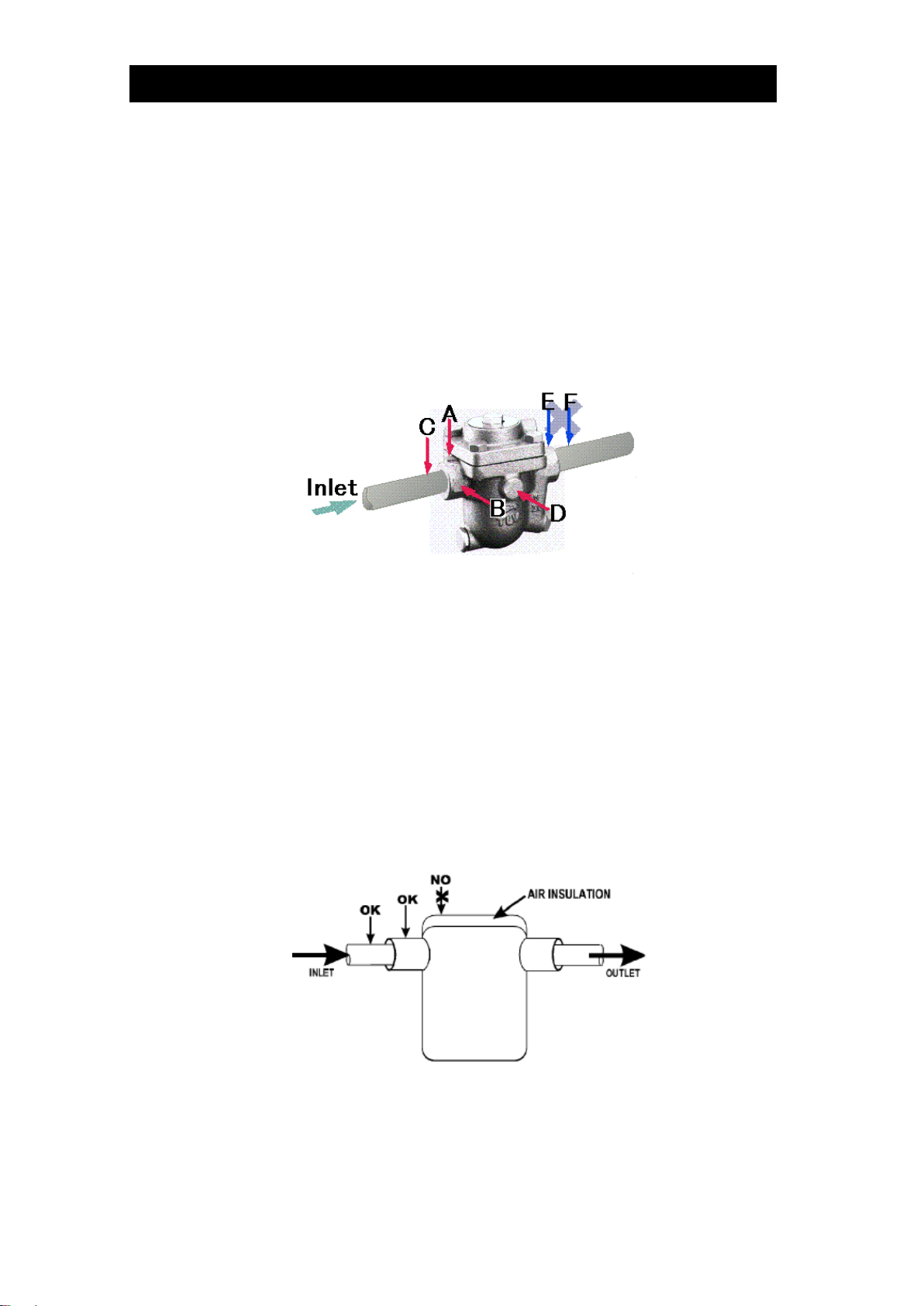
3.3 Measurement Position
3.3.1 Standard horizontal pipes
Traps should be measured at the trap inlet, which may be at the bottom of the trap in some
instances. Hold theprobe perpendicular tothe flat surface at the inlet and press firmly for 15
seconds.
The point at which the measurement is taken must be filed smooth and flat with the file
delivered with the unit. Refer to "6.3 Using the Probe".
The standard measurement position is point A in the figure below.
If the trap cannot be measured at point A, point B, C or D may be substituted. However,
please note that the accuracy of judgements will be adverselyaffected if measurements are
made at points other than the standard point A.
Also note that judgements cannot be made at points E and F at the trap outlet.
Before measurement begins, close the Lock Release Valve (LRV) on the trap if equipped.
Set the LRV to its previous position once measurement is completed.
For bucket traps with air insulation, the inspection surface should be prepared on the
steam piping ahead of the trap inlet or on the trap inlet. Do not measure from the top of the
trap.
OK: Standard measurement point
NO: Will result in incorrect measurement

172-65592MA-07 (TM5N/TM5N-EX TrapMan Type P) 12 May 2022
16
3.3.2 Standard vertical pipes
Traps should be measured at the trap inlet, which may be at the bottom of the trap in some
instances. Hold theprobe perpendicular tothe flat surface at the inlet and press firmly for 15
seconds.
The point at which the measurement is taken must be filed
smooth with the file delivered with the unit. Refer to "6.3
Using the Probe".
The standard measurement position is point A or point B [in
the figure below].If the trap cannot be measured at point A or
point B, point C may be substituted. However, please note
that the accuracy of judgements will be adversely affected if
measurements are made at points other than the standard
point A or point B.
Also note that judgements cannot be made at points E and F
at the trap outlet.
3.3.3 Universal type
Traps should be measured at the trap inlet, which may be at the bottom of the trap in some
instances. Hold the probe perpendicular to the flat surface at the inlet and press firmly for
15 seconds.
The point at which the measurement is taken must be filed smooth with the file delivered
with the unit. Refer to "6.3 Using the Probe".
The standard measurement position is point A [in the
figure below].
If the trap cannot be measured at point A, point C may
be substituted. However, please note that the
accuracy of judgements will be adversely affected if
measurements are made at points other than the
standard point A.
Also note that judgements cannot be made at
points E and F at the trap outlet.
For bucket traps with a universal connector, the inspection surface should be prepared
on the top of the face of the connector if there is no nameplate, or on the flat on the top of
the connector.
OK: Standard measurement point
NO: Will result in incorrect measurement
3.3.4 Other installation

172-65592MA-07 (TM5N/TM5N-EX TrapMan Type P) 12 May 2022
17
Traps should be measured at the trap inlet, which may be at the bottom of the trap in some
instances. Hold theprobe perpendicular tothe flat surface at the inlet and press firmly for 15
seconds.
The point at which the measurement is taken must be filed smooth with the file delivered
with the unit. Refer to "6.3 Using the Probe".
The standard measurement position is point A in the figure below.
If the trap cannot be measured at point A, point B may be
substituted. However, please note that the accuracy of
judgements will be adversely affected if measurements are
made at points other than the standard point A.
Also note that judgements cannot be made at points E
and F at the trap outlet.
3.3.5 Trap station
Traps should be measured at the trap station inlet.
The point at which the measurement is taken must be filed smooth with the file delivered
with the unit. Hold the probe vertically to the flat surface at the inlet and press firmly for 15
seconds. Refer to "6.3 Using the Probe".
The standard measurement position is point A. (Figure below shows the point where the
probe should be pressed to.)
If the trap cannot be measured at point A, point B and C may be substituted. However,
please note that the accuracy of judgements will be adverselyaffected if measurements are
made at points other than the standard point A.
Also note that judgements cannot be made at points E and F.
172-65592MA-07 (TM5N/TM5N-EX TrapMan Type P) 12 May 2022
18
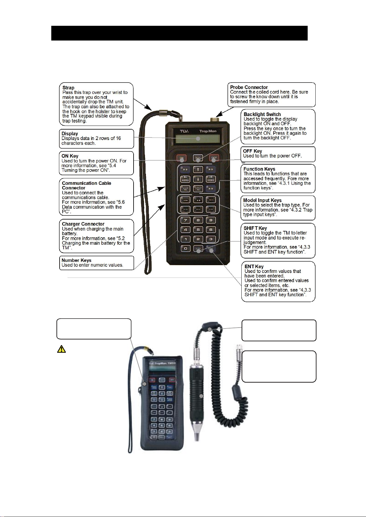
4. Part Names
4.1 TM Unit
4.2 Probe and Leather Case
Probe
Pressed and held against the
filed clean flat surface at the trap
inlet for 15 seconds to take
measurements.
Coiled Cord
Used to connect the probe to the
TM unit.
Used to protect theTMunit from
dirt and dust.
WARNING
The TM5N-EX (intrinsically
safe) must always be inserted in
this leather case while used in
hazardous locations.
Do not wipe/rub the surfaces of
this product with a dry cloth etc.
There is the danger of
electrostatically charging the
unit, which may result in fire or
explosions, especially in
explosion hazard areas.
The maximum measured
capacitance from the probe
receptacle to ground is 14.3pF.
The user shall determine
suitability in the specific
application.
Leather Case (TM5N-LC-EX)

172-65592MA-07 (TM5N/TM5N-EX TrapMan Type P) 12 May 2022
19
4.3 Function Keys
4.3.1 Function keys
DATA
TRANS
Used for data transfer with the PC.
FUNC
Used to tabulate inspection data and change settings.
INFO
Used for entering detailed data on pipes and the operating
conditions for measured traps, etc.
Used to scroll through the screens for recalling inspection data
selecting INFO key items, registering/recalling trap model
names.
CALL
JUDGE
Used to toggle the display between the stored judgement and the
model name, and to move the cursor to the left.
MODIFY
JUDGE
Used to modify a stored judgement, and to move the cursor to
the right.
AREA
NO.
TRAP
NO.
Used to enter and recall the control numbers for area and trap
number
4.3.2 Trap type input keys
OTHERS
TEMP.
ADJ
FLOAT
THERMO
BUCKET
DISC
These keys are used to enter and register trap models.
Up to 30 model names can be entered for each trap type.
4.3.3 SHIFT and ENT key functions
SHIFT
Used totoggle themode for control number input to capital letters,
and to execute re-judgement.
ENT
Used to confirm entered values or selected items, etc.
This manual suits for next models
1
Table of contents
Popular Control System manuals by other brands


Tecnoalarm
Tecnoalarm TP8-64 BUS Installer manual

ORTAL
ORTAL Heat Control System Installation and operation manual

Sutter Instrument
Sutter Instrument SmartShutter Lambda SC Operation manual

ION
ION Ion SYST0101CW Installation & quick start guide

Siemens
Siemens SIMATIC C7-635 manual

DEEP SEA ELECTRONICS
DEEP SEA ELECTRONICS DSE8610 MKII Operator's manual